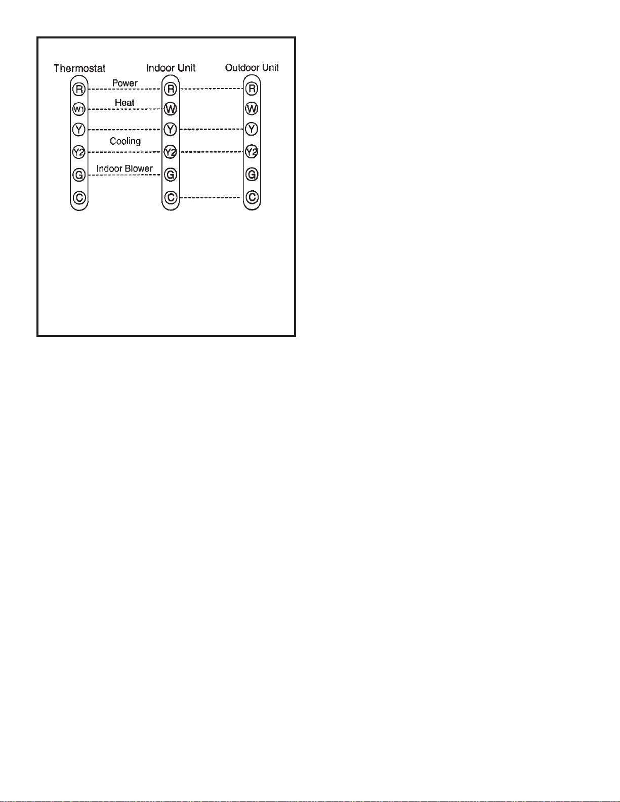
Thermostat Designations
See unit wiring diagram for power supply connections.
If the indoor unit is not equipped with a blower relay, one must
be field supplied and installed.
Do not connect C (common) connection between indoor unit
andthermostatexcept whenrequired bytheindoor thermostat.
Refer to thermostat installation instructions. C (common)
connection between indoor unit and outdoor unit required for
proper operation.
Figure 4
Refrigerant Piping
If the 4SCU18LT unit is being installed with a new indoor
coilandline set,the refrigerant connectionsshould bemade
asoutlinedinthis section. If anexistinglineset and/or indoor
coilwill beused tocomplete the system, refer tothis section
as well as the section that follows entitled - Flushing
Existing Line Set and Indoor Coil.
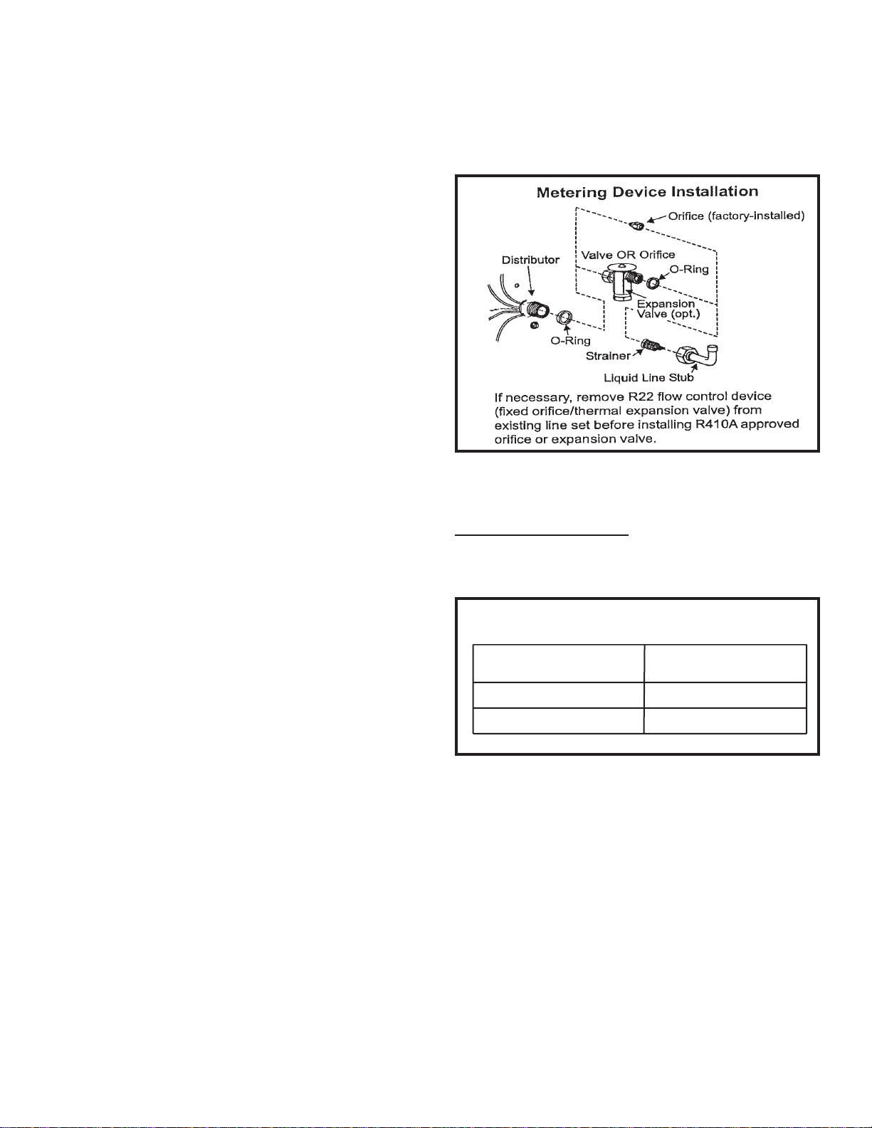
If this unit is being matched with an approved line set or
indoor coil which was previously charged with R-22
refrigerant, the line set and coil must be flushed prior to
installation. Iftheunit is being used withand existingindoor
coilwhich was equipped with a liquid line which served as a
meteringdevice(RFCI),the liquid linemustbereplaced prior
to the installation of the 4SCU18LT unit.
Field refrigerant piping consists of liquid and suction lines
from the outdoor unit (sweat connections) to the indoor coil
(flare or sweat connections).
Select line set diameters from Table 2 to ensure that oil
returns to the compressor. Size vertical suction riser to
maintain minimum velocity at minimum capacity.
Recommended line length is 50’ or less. If more than 50’
line set is required, contact Technical Services. Table 2
showsthediameters forline sets upto 100’althoughvertical
lift applications and trapping requirements need to be
reviewed with Technical Services for line sets over 50’.
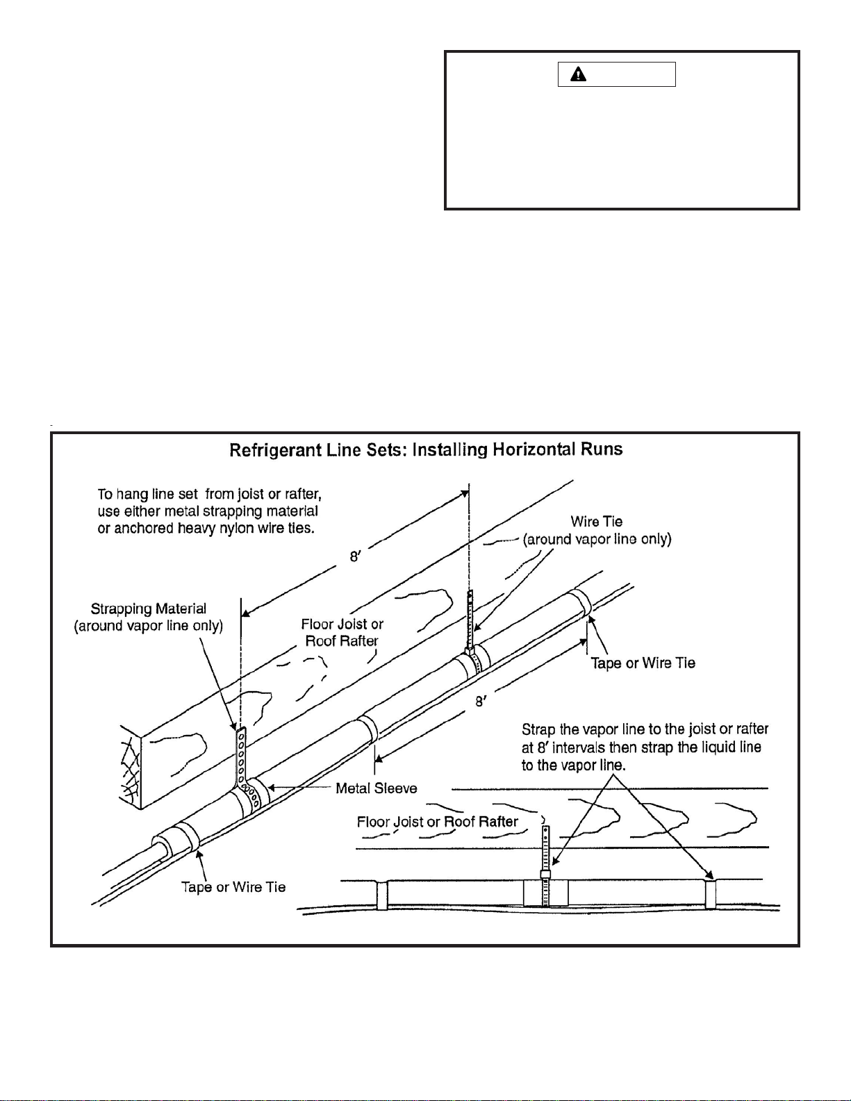
Installing Refrigerant Line
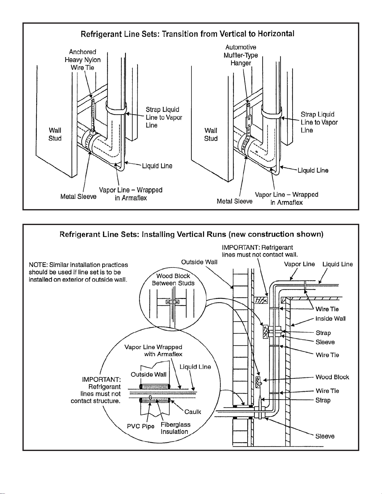
During the installation of an air conditioning system, it is
important to properly isolate the refrigerant line to prevent
unnecessary vibration. Line set contact with the structure
(wall, ceiling, or floor) may cause objectionable noise when
vibration is translated into sound. As a result, more energy
or vibration can be expected. Close attention to line set
isolation must be observed.
Following are some points to consider when placing and
installing a high-efficiency outdoor unit:
1. Install line voltage power supply to unit from a properly
sizeddisconnectswitch. Anyexcesshigh voltagefield wiring
should be trimmed or secured away from the low voltage
field wiring.
2.Groundunitatunitdisconnectswitchortoanearthground.
To facilitate conduit, a hole is in the bottom of the control
box. Connect conduit to the control box using a proper
conduit fitting. Units are approved for use only with copper
conductors. 24V Class II circuit connections are made in
the low voltage junction box. Refer to Figure 4 for high
voltagefield wiring diagram. Acomplete unit wiring diagram
is located inside the unit control box cover.
3.Installroomthermostaton an insidewall that isnotsubject
to drafts, direct sunshine, or other heat sources.
4. Install low voltage wiring from outdoor to indoor unit and
from thermostat to indoor unit (See Figure 5).
5. Do not bundle any excess 24V control wire inside control
box. Run control wire through installed wire tie and tighten
wire tie to provide low voltage strain relief and to maintain
seperation of field-installed low and high voltage circuits.
506254-01 Page 4 of 25Issue 0912