Maxon MXI 18HC001 User manual

Split air conditioner
Wall mounted Type
Service manual
MXI 18HC001- / MXO-18HC001
MB FRIGO Grupa d.o.o., Bani 81, 10010 Zagreb, tel: 01/66 08 002, fax: 01/66 08 005

1
CONTENTS
11
Contents
Safety precautions
Installation
Block diagram
Trouble shooting
Fault diagnosis by symptom
Control specification
To disassemble mechanical parts
Exploded views and parts list
Wiring diagrams
22
22
1111
1212
1313
1717
2121
2525
4141

The following safety precautions must be taken when using your air
conditioner.
SAFETY PRECAUTIONS
1. Warning: Prior to repair, disconnect thepower cord.
2. Use properparts: use onlyexact replacement parts.(Also, we recommend replacing parts rather
than repairing them.)
3. Use theproper tools: use the proper toolsand test equipment, and know howto use them. Using
defective tools ortest equipment may cause problems later-intermittentcontact, for example.
4. Power cord:prior to repair, check the power cord andreplace it if necessary.
5. Avoid using anextension cord, andavoid tapping intoa power cord.This practice may result in
malfunction or fire.
6. Aftercompleting repairs and reassembly, check the insulation resistance.
Procedure: prior toapplying power, measure the resistancebetween the power cord and theground
terminal. The resistance must be greater than 30megohms.
7. Make surethat the grounds are adequate.
8. Make surethat the installation conditions are satisfactory. Relocate the unit if necessary.
9. Keep childrenaway from the unit while itis being repaired.
10. Be sureto clean the unit and itssurrounding area.
1
2
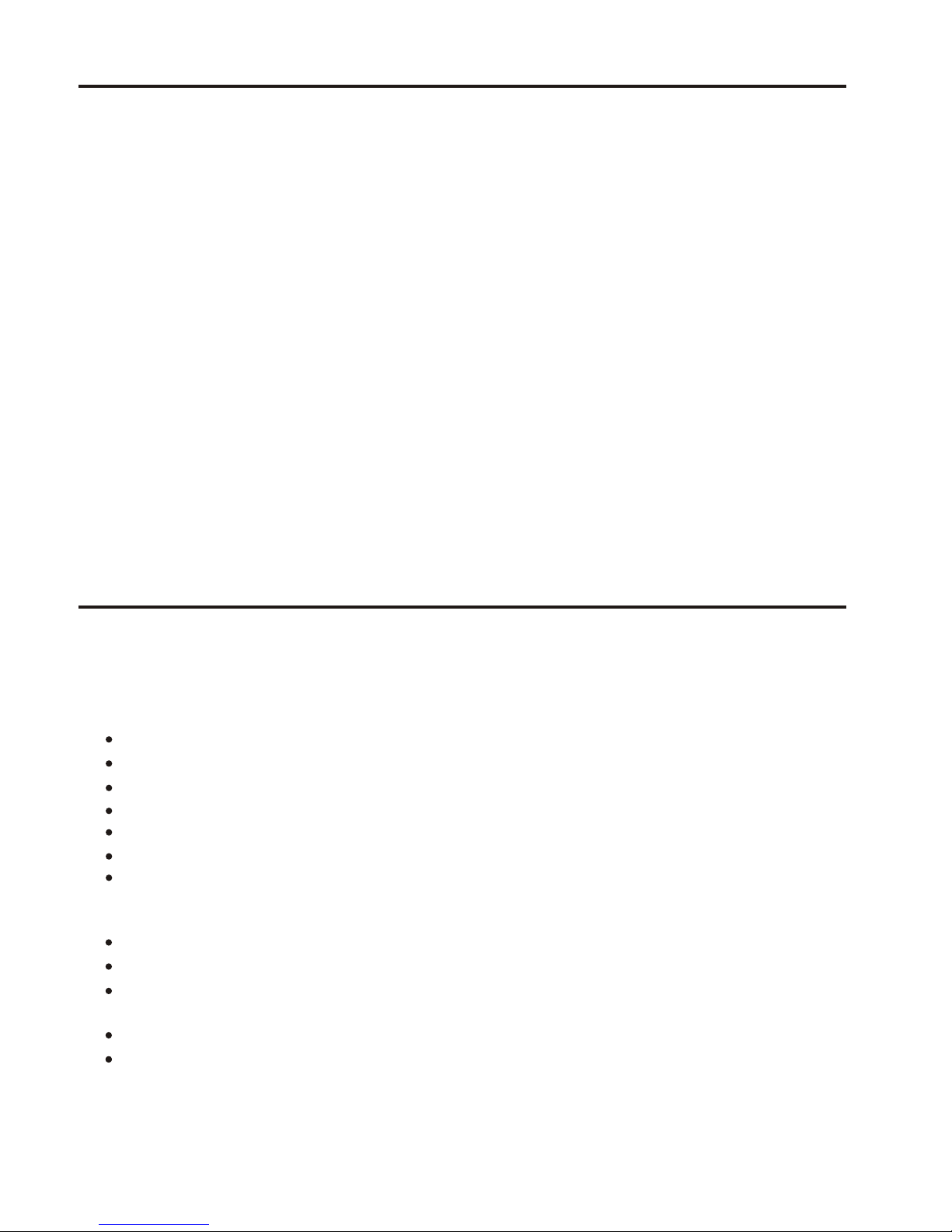
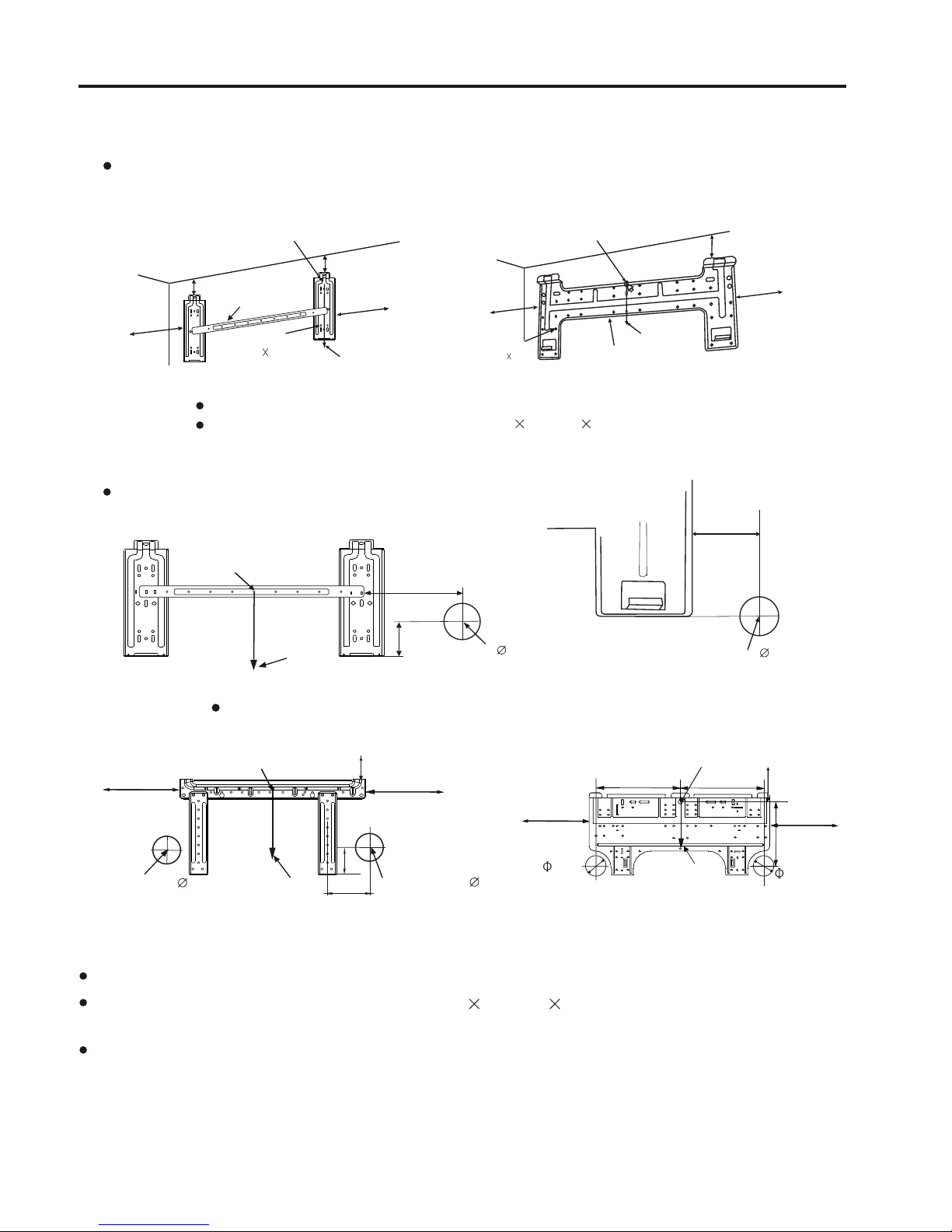
Location of indoor unit
A place solid enough to bear the weight of the unit and not cause any shake.
Good ventilation, less dust, far from direct rain and sunshine.
Avoid places close to inflammable gas leakage.
Keep the air inlet and outlet at a far distance from the blockage.
Keep the height distance between the indoor and outdoor unit at most 5m.
Mount on the wall solid enough to bear the weight of the unit and not cause any shake.
Avoid direct sunshine.
A place easy for condensate drain and easy for connecting with the outdoor unit.
Keep a far distance away from the fluorescent lamp, it may influence the operation of remote controller.
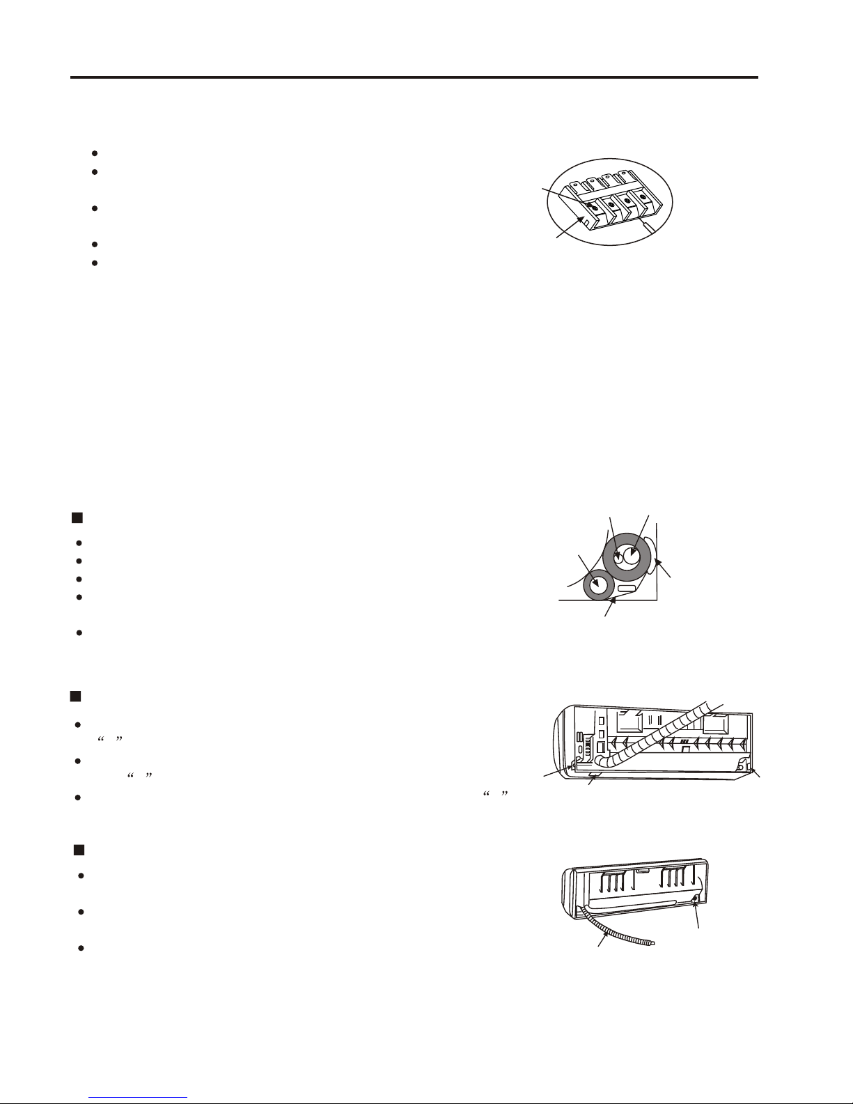
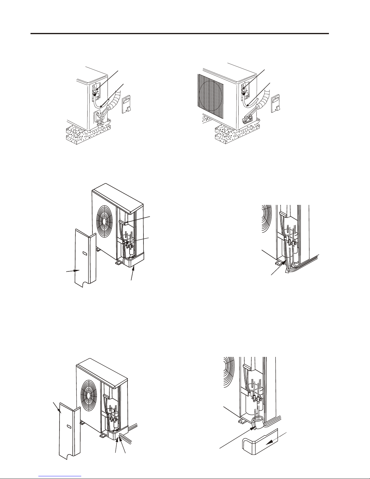
Location of outdoor unit
Keep at least 1m away from the TV radio and other home appliances.
A place where the air discharged out of the outdoor unit or the operation noise will not annoy your
neighbours.
No blockage near the outdoor unit.
Avoid places close to inflammable gas leakage.
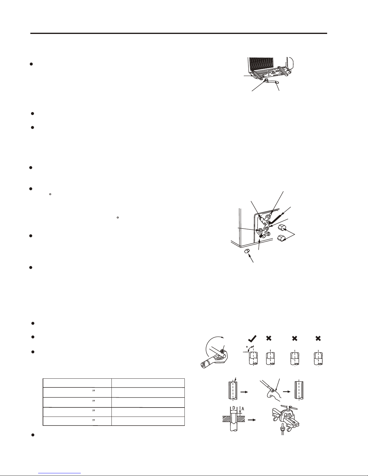
Selecting area for installation
INSTALLATION
Select an area for installation that is suitable to the customer’s needs.
It is harmful to the air conditioner if it is used in the following environments: greasy areas (including area
near machines). Salty area such as coastal areas, areas where sulfuric gas is present such as hot spring
areas. Contact your dealer for advice.
Caution:
2

front
right
back
Underside Left-back
back
Notice: do not elevate the
drain hose.
The copper pipe can be led
from back, right, underside,
or left-back side.
Cover connecting pipe with
adiabatic material.
Sponge plastic adiabatic
material with the
thickness of 8mm.
While installing the pipeline on the
thin armor plate or on the wall of
metal mesh, you should use the
wooden board to clamp between
the wall and the pipeline, or wrap
up the pipeline with 7-8 layers of
insulating plastic tape.
left
100mmÒÔÉÏ
above 300mm
above 500mm
above 300mm
above 500mm
above 500mm
INSTALLATION
Installation diagram of indoor unit and outdoor unit
Confirm the installation position by the mark of the indoor mounting plate.
or
or or
above 155mm
above 250mm
Above 20mm
above 105mm
3

Securing the mounting plate and drill on the wall
1
Secure the mounting plate
The mounting plate should be attached to the structural part of wall (post etc).
fasten string at the central hole
105mmormore
from sidewall
155mmor more
at least 250mm
fromsidewall
Tapping screw
ST4 25(5)
mounting plate
NOTICE: The holes at solid arrow position must be secured to avoid the shake of mounting plate.
When the expansion bolts are used, two holes ( 11 20 or 11 26 ) that the distance
between them is 450mm should be adopted.
Drill on the wall
Center of hole( 65mm)
Confirm the position of holes, and drill holes on the wall.
NOTICE:
Fasten string at the central hole
105mm or more
from sidewall455mm or more
at least 250mm
from sidewall
Tapping screw
ST4 25(5)
mounting plate
plumb
40mm
atleast24mm
plumb
fasten string at the central hole
105mm
45mm
Center of hole( 65mm)
plumb
NOTICE:
The holes at solid arrow position must be secured to avoid the shake of mounting plate.
When the expansion bolts are used, two holes ( 11 20 or 11 26 ) that the distance
between them is 450mm should be adopted.
Confirm the position of holes, and drill holes on the wall.
INSTALLATION
440mm
fasten string at the central hole
at least250mm
230mm
440mm
at least 120mm
at least 120mm
90mm
plumb
90mm
Pipe hole
40mm
Pipe hole
plumb
fasten string at the central hole
at least 250mm
at least 180mm
at least 140mm
120mm
Center of hole( 65mm)
4

Wiring
2
Open the front grille;
Remove the screw from electrical box cover, pull the
electrical box cover away from the unit and set aside.
Remove the screw from fastener, pull the fastener
away from the unit and set aside.
Connect the cable.
Replace the fastener and electrical box cover.
Indoor unit terminal
Screw
Connecting cable
Diagram
INSTALLATION
The drain hose must be arranged beneath the copper pipe.
The drain hose must not be hunched or twisted.
While wrapping up the drain hose, do not pull it.
The drain hose through the room must be wrapped up by the
thermal insulation materials.
The copper pipe and the drain hose must be wrapped up by felt
strip. Adiabatic pad should be used at where the pipe contacts
the wall.
NOTE:
1
23
ROUTE OF PIPE
If pipe comes out of the right side of the indoor unit, cut part
1 of the unit;
If pipe comes out of the lower-right side of the indoor unit, cut
part 2 of the unit;
If pipe comes out of the left side of the indoor unit, cut part 3
of the unit.
Installation of the drain hose
3
Drain hose
gaspipe
Liquid pipe
felt
Adiabatic
underlay
drain hose
If pipe comes out of the left side of the indoor unit, the drain hose
must be refitted, otherwise water leakage may occur.
Refit methods: Interchange the position of drain hose and drain
rubber plug.
Clearance is not allowed after refit, it would lead to water leakage.
Drain rubber
plug
REFIT OF DRAIN HOSE
5
NOTE:
The appliance shall be installed in accordance with national wiring regulations.
The appliance must not be installed in the laundry.
The appliance must be installed 2.3m above the floor.
The appliance must be positioned so that the plug is accessible.
For some modelswhose cooling capacity are above 4600W(17000BTU/h),
an all-pole disconnectiondevice which has at least 3mmseparation distance in
all pole anda residual current device(RCD)with the ratingof above 10mAshall
be incorporated inthe fixed wiring according to thenational rule.

Arrangement of the drain hose
To drain the condensate water easily, the drain hose should be declined downwards.
The following 5 arrangement methods are incorrect.
Decline
downward
(Fig. 1) (Fig. 2) (Fig. 3) (Fig. 4)
Water
leak
Standing water
air
Dip hose
into water
(Fig. 5)
50mm or less
above floor
Decline
downward
Water
leak
Water
leak
If you find the drain hose not long enough to connect with the indoor
unit, you can extend it with the hoses in the accessory box.
The drain hose through the room must be wrapped up with the special
adiabatic material.
Drain hose
Hose(ID 15cm)
PVC hard
INSTALLATION
5
Pipe Connection
DIAMETER OF PIPE
6.35mm ( 1/4 )
9.52mm ( 3/8 )
12.7mm ( 1/2 )
TORQUE(N m)
13.7---17.6
34.3---41.2
49.0---56.4
Align the centre of joint in line with that of flare and tighten the nut of connecting pipe with wrench.
Put some seal oil to cover the joint and the flare.
15.88mm ( 5/8 ) 73.0---78.0
The number of bent position of the pipe in the indoor unit should not exceed 10.
The number of bent position of the pipe in the indoor unit and the outdoor unit should not exceed 15.
The radius of bent position should be more than 10cm.
Evaporator
craft tube
Do not exhaust the inside air just by loosing the nut since there is the air of certain pressure
inside the tube of indoor unit. Please do not make extra effort for fear of damaging the flare.
Attention:
Please break the evaporator craft tube with pincers before connecting. After exhausting the inside air,
use the wrench to twist down the nut of connecting tube of the evaporator.
Installation of the indoor unit
Let pipe go through the wall hole and attach the indoor
unit to the mounting plate.(Press the rib of indoor unit
inside the hook of the mounting plate.) the rib of indoor unit
the mounting plate
Bottom
Indoor unit
4
Wall sealing and Pipe fastening
Use putty to seal the wall hole.
Use clamp (pipe fastener) to secure the pipe at specified position.
Indoor unit
clamp
screw
get rid of unwanted part
seal with putty
secure the connecting
pipe with clamp
6
6

INSTALLATION
Connecting
cable
Outdoor unit terminal
1
Wiring
1 Remove theself-tapping screws (2 pcs)
on the maintenanceboard and take out the
maintenance board.
Maintenance
board
Terminalboard
Fix the cablewire
with anchor cable
Piping cover
Please utilize outdoorpipe support when
the cable wireis led from the backside.
Outdoor pipe support
(Outdoor pipe supportis not required
when leading thecable wire from other places).
The cable wire can be led from theback hole
of the pipinghole or ejecting hole.
Maintenance
board
Piping cover Ejecting hole
Right wiring
Back wiring
Sponge
Piping cover
2 Loosen theself-tapping screws (2 pcs) on
the fixing clip to loosen thefixing clip.
5 Install themaintenance board. After the pipes
and cable wireare installed, please seal the
sponge block asper drawing indication.
3 Loosen thefixing screw of the wire terminal
board, pass thepower wire and signal wire
through the fixing clip. Then firmly fix the
power wire andsignal wire on the terminal
board with thefixing screw. (Earth wire
must be connectedfirmly.)
4 Tightenthe self-tapping screw on the fixingclip.
Wiring For Above 6000W Model (Above 21000BTU/h Model)
Connecting
cable
Outdoor unit terminal
or
Installation diagram of indoor unit and outdoor unit
7

INSTALLATION
8
If the interconnectioncord for powersupply has tobe replaced, pleasesee the
following table for reference.
Notice:
If the signal wire hasto be bought separately, choose electric wire above 0.75mm.
MODEL SPECS (Interconnection cord)
2700W(10000BTU/h) 1.0mm
3000W(11000BTU/h) -4000W(15000BTU/h)
4500W(18000BTU/h) -8000W(28000BTU/h) 2.5mm
1.5mm
2
2
2
2
WARNING:
Special cable must be used to connect indoor unit and outdoor unit. It should be ensured
that the terminals are not influenced by external force. Poor connection may cause fire.
The electric box cover must be mounted and secured in position, otherwise fire or electrical
shock may occur because of dust or moisture.
The connecting cables must be clipped together.
Please take the electric circuit diagram attached to the indoor/outdoor units as major
reference while installing.
The power wire and signal wire between the indoor/outdoor units must be connected
one by one as per corresponding number on the wiring terminal board.
All the models shall be connected with the mains which has system impedance limitations.
While installing the unit, please see the following table for impedance information or
consult with the supply authority.
The temperature of refrigerant circuit will be high, please keep the interconnection cable away
from the copper tube.
3500W (12000BTU/h) 0.219
5100W (18000BTU/h) 0.186
R410A
series
6800W (18000BTU/h) 0.124

Burr
Oblique
Copper pipe
90 Roughness
Reamer
Burr
Outer diameter A(mm)
2.0--2.5
3.0--3.5
3.5--4.0
6.35mm ( 1/4 )
9.52mm ( 3/8 )
12.7mm ( 1/2 )
15.88mm(5/8 ) 4.0--4.5
Air exhausting
4
Installation of the drain joint(only for heat pump type)
Bottom
Double-channel
drain joint Drain hose
Joint of the connecting pipe
Put some seal oil to cover the joint and the flare.
Align the centre of joint in line with that of flare and tighten the nut of connecting pipe
with wrench. ( Adjust the torque by the same method of connecting pipe for indoor unit.)
Insert the outdoor double-channel drain joint in one of the
bottom holes of the suitable size then connect drain hose
and joint together.
2
3
gas shut-off
valve
liquid shut-off valve
service port
gas connecting
pipe
liquid connecting pipe
valve nuts
service port cap
allen wrench
Screw down the cap of both gas shut-off valve and
liquid shut-off valve as well as the nut of service port.
Use Allen wrench to turn the valve cork of liquid side
at 90 counter-clockwise, and close it after 10 seconds.
Use soapy water to check the gas leakage especially
at all joint. If there is no gas leakage, please turn the
valve cork of liquid side at 90 counter-clockwise again.
Press the cork of service port at gas shut-off valve, 10
seconds later, when you see foggy gas discharged, that
means inner air is exhausted out.
Use Allen wrench to turn the valve cork of both liquid
shut-off valve and gas shut-off valve counter-clockwise
until they are completely open and then replace the
valve caps and tighten them.
Process of flared tube
5
Use the pipe cutter to cut off the broken part of flare.
Remove burrs at the cut of the flare.
Insert a nut into the connecting pipe and do flaring
with specified flaring tools, reamers for example.
Check the quality of flaring technique.
INSTALLATION
Remove burrs at the cut of the flare.
9

Screw the gas shut-off valve to close, connect
charging hose(low pressure) to the service valve
and then open gas shut-off valve again.
Connect the refrigerant bottle to the charging hose
and then convert it.
Disconnect the manifold gauge after turning off the
shut-off valve, and then open gas shut-off valve again.
Exhaust the air as the above-mentioned method.
Tighten nuts and caps of each valve.
Fill in liquid refrigerant as the above table. Service port
Manifold gauge
Low pressure
valve
High pressure
valve
Pressure meter
Charging line
Adding refrigerant
If the connecting pipe is longer than 7 metres, add refrigerant as needed. (Cool only type) added
amount A=(Lm-7m) 15g/m ; (Heat pump type)added amount A= (Lm-7m) 50g/m. ( A: amount
of added refrigerant, L: the length of connecting pipe)
6
7
0
0
8
15
50
9
30
100
10
45
150
The length of connecting pipe (m)
(Cool only type)added amount (g)
(Heat pump type)added amount (g)
INSTALLATION
Set the unit to cool operation mode.
Stop operation of the air conditioner.
Relocation of the air conditioner.
Refer to this procedure when the unit is relocated.
1. Carry out the pump down procedure.
2. Remove the power cord.
3. Disconnect the assembly cable from the indoor and outdoor units.
4. Remove the flare nut connecting the indoor unit and the pipe.
At this time, cover the pipe of the indoor unit and the other pipe using a cap or vinyl plug to avoid foreign
material entering.
5. Disconnect the pipe connected to the outdoor unit.
6. Make sure you do not bend the connection pipes in the middle and store together with the cables.
7. Move the indoor and outdoor units to a new location.
8. Remove the mounting plate for the indoor unit and move it to a new location.
7
10

Operation test
8
INSTALLATION
Before test operation, wiring safety inspection must be carried out carefully again.
1. Emergency switch operation: Every press of emergency switch, the
air conditioner runs as in the following order:
Cool only type: Cool Shut off
Heat pump type: Cool Heat Shut off
2. Remote controller operation: If the indoor unit sounds like Di, Di when pressing I/O button,
that indicates the air conditioner is under the operation of remote controller. After that, press
every button to test their functions.
3. operation: Open the front grille and press the check button. Switch on the powerCheck switch
source and then the operation test is activated. If the indicator lamps light up at first and then
go out in succession or the LED window of the indoor unit illuminates at first and then goes out,
the system is under normal operation. If one of the indicator lamps is flashing at all times, or
failure codes are displayed on the LED window of the indoor unit, the system has something
wrong and please check malfunction immediately.
Check valve
Capillary tube
Capillary tube
Liquid side
2-way valve
Gas side
3-way valve Accumulator
Compressor
4-way valve
Cross fan
Heat
exchanger
(Condenser)
Propeller fan
Heat
exchanger
(Evaporator)
INDOOR UNIT OUTDOOR UNIT
Cooling
Heating
Gas leak check point
BLOCK DIAGRAM
Refrigerant Cycle Block Diagram
11

TROUBLE SHOOTING
Items to be checked first
1. Is the voltage of the power correct?
The input voltage shall be rating voltage 10%.
The air conditioner may not operate properly if the voltage is out of this range.
2. Is the link cable connecting the indoor unit and the outdoor unit linked properly?
Please refer to the “wiring diagram”
Check the terminals if the indoor unit and outdoor unit are properly linked by the same number of cables.
3. When a problem occurs due to the contents illustrated in the table below, it is symptom not related to the
malfunction of the air conditioner.
Operation of air conditioner
In COOL operation mode, the compressor does not operate
at a room temperature higher than the setting temperature
that the indoor fan should operate.
In a HEAT operation mode, the compressor does not
operate at a room temperature lower than the setting
temperature that indoor fan should operate.
It happens after a delay of 3 minutes when the compressor is
reoperated. The same phenomenon occurs when a power is on.
As a phenomenon that the compressor is reoperated after a
delay of 3 minutes, the indoor fan is adjusted automatically with
reference to a temperature of the air blow.
Fan speed setting is not allowed in AUTO or DRY mode. The speed of the indoor fan is set to low in DRY mode.
Fan speed of 3 steps is selected automatically in AUTO mode.
Explanation
Compressor stops operation intermittently in DRY mode. Compressor operation is automatically controlled in DRY mode
depending on the room temperature and humidity.
Compressor of the outdoor unit is operating although it is
turned off in HEAT mode.
When the unit is turned off while de-ice is activated, the
compressor continues operation for up to 10 minutes(maximum)
until the deice is completed.
Timer indicator lamp lights up and the air conditioner does
not operate.
Timer is being activated and the unit is in ready mode.
The unit operates normally if the timer operation is cancelled.
The compressor and indoor fan stop intermittently in HEAT
mode.
The compressor and indoor fan stop intermittently if room
temperature exceeds a setting temperature in order to protect
the compressor from overheated air in HEAT mode.
Indoor fan and outdoor fan stop intermittently in HEAT mode. The compressor operates in a reverse cycle to remove exterior
ice in HEAT mode, and indoor fan and outdoor fan do not
operate intermittently for within 20% of the total heat operation.
The compressor stops intermittently in COOL mode or DRY
mode, and fan speed of the indoor unit decreases.
The compressor stops intermittently or the fan speed of the
indoor unit decreases to prevent inside/outside air frozen
depending on the inside/outside air temperature.
SELF DIAGNOSIS FUNCTION
Our company provides the end-users with thoughtful services by installing various diagnostic systems to
indicate the following irregular performances.
Check code Diagnosis of malfunction
FAULT F7
FAULT F8
FAULT F9
Indoor TEMP sensor faults
Indoor coil pipe TEMP sensor faults
Outdoor coil pipe TEMP sensor faults
FAULT F6 PG motor faults
12

FAULT DIAGNOSIS BY SYMPTOM
No cooling
effect at all
Fan motor
error
Fan motor orits capacitor faults.
Loose connection orbadly contact.
compressor
does not operate
Control circuit error.
Voltage mayappear a littlelower or higher.
Loose or wrongconnection.
Compressor faults orjumps for overloading.
Control circuit error.
Leakage of
refrigerant Recharge the refrigerantat leaking place.
Block of thecooling
system
Poor cooling
efficiency
Insufficient
refrigerant Some cracks, weldingfailure in thesystem.
Air filter is
blocked
No periodical cleaning.
Accumulated lampblack, dust or
Accumulated lampblack, dustor contaminated
ambient environment.
Toohigh ambient
temperature
The outdoor unitgets exposed tothe sun for too
long period.
Air conditioning burden
is not adequatefor the
room
The capillary,pipeline are blockedor the valve
is not openor the connectingtube is folded flat.
The doors andwindows are notclosed well;
too weak ofinput cooling poweror too many
heat resources inthe room.
Some leakage inthe valve.
No cooling
The four-way
valve error
Blockage in
the system
The valve isnot completely open;the capillary or
Pipeline is halfblocked.
Connecting tube isfolded flat.
The distributing airof the four-wayvalve may havemixed
together; the valvecore or solenoidvalve faults.
Low airflow volume
Low fan motorfrequency or capacitoris not
functional.
Low fan speedor the fanmotor faults.
Extra fluorin isadded during mounting.
Mounting location is not suitable, such as near the wall.
Air outlet isblocked or accumulatedlampblack
or dust isattached to thevane.
Poor efficiency of
heat dissipating on
the outdoor unit
Not for residentialuse.
13

No heating
effect at all
Fan motor
error
Fan motor orits capacitor faults.
Loose connection orbadly contact.
compressor
does not operate
Control circuit error.
Voltage mayappear a littlelower or higher.
Loose or wrongconnection.
Compressor faults orjumps for overloading.
Control circuit error.
Leakage of
refrigerant Recharge the refrigerantat leaking place.
Block of the cooling
system
Poor heating
efficiency
Insufficient
refrigerant Some cracks, weldingfailure in thesystem.
Air filter is
blocked
No periodical cleaning.
contaminated ambient environment.
Toolow ambient
temperature Below 0 .
Toothick frost
generated on the
condenser.
The condenser doesnot defrost, nosmooth air
circulation.
Extra refrigerant or
mixing air inthe system Discharge the redundantrefrigerator recharge
the refrigerant aftervacuum extraction.
The condenser istoo dirty
Air conditioning burden
is not adequatefor the
room
Accumulated lampblackor dust isattached
to the vane.
The capillary,pipeline are blockedor the valve
is not openor the connectingtube is foldedflat.
The doors andwindows are notclosed well;
too weak ofinput cooling/heating power.
Some leakage inthe valve.
No heating
The four-way valve
or solenoid valvefaults.
The four-way valvedid not commutateor the
distributing air ofthe four-way valvemay
have mixed together.
The electric heateris
not working
Not satisfy theconditions for electricheater
running.
Plug cords may be loose.
The four-way
valve error
Blockage in
the system
The valve isnot completely open;the capillary or
Pipeline is halfblocked.
Connecting tube is folded flat.
The distributing airof the four-wayvalve may havemixed
together; the valvecore or solenoidvalve faults.
Low airflow volume
Low fan motorfrequency or capacitoris not
functional.
Low fan speedor the fanmotor faults.
Extra fluorin isadded during mounting.
FAULT DIAGNOSIS BY SYMPTOM
14

Noise from
indoor unit
Collision sound
of the machine
Flowing sound
of the liquid
Sound of the
running fan motor
Sound of plastic
pieces rubbing or
deforming
Oscillation
sound
Sound of running
fan motor Vane imbalanceor distortion.
Sound made by
cooling operation Refrigerant circulation orvane distortion.
Sound of running
compressor
Something wrong withthe compressor,such as
oil shortage, valveslice distortion.
Noisy
Fixing bolts somewheremay loose orrub, some
spare parts maynot match verywell.
Refrigerant circulation orpressure change of
refrigerant while switchon/off.
Vane imbalanceor distortion, rupture; loose
screw of vane.
Plastic pieces deformdue to expansionwhen
hot and shrinkwhen cold. Orsome spare parts
may not matchvery well.
Noise from
Outdoor unit
Collision sound
of the machine
Collision of thepipeline, fixing screwsloose or
deform caused byrubbing.
Inappropriate installation method; the unit
does not matchwith the installationkit very well
or the compressorquivers acutely.
The whole unitresonates thedoor andwindow.
Sound made by
compressor or motor The compressor ormotor makes abnormalnoise.
Condensed water isattached to thevane.
Vane imbalanceor distortion.
Resonance sound
Collision sound of the
machine
Flowing sound of
condensed water
Sound of runningfan
motor
Noise from
the whole
unit
The unit doesnot match withthe installation kit
very well
Collision of thepipeline, fixing screwsloose or
plastic pieces deform.
FAULT DIAGNOSIS BY SYMPTOM
15

Switching on theair conditioner
The current leakageswitch
jumps to turnoff
Junction wire loosesand collides with the outer
cover.
Degraded capability ofwire insulation.
Insulation capability of
some components has
lowered.
Check the resistance
of every component
by multimeter
Water comesinto the plug or electric components.
The fuse isblown
or air limitswitch
jumps to turnoff
Is the voltage
of power supplylower
than 15% ofrated voltage
(220V)?
Yes The voltage islow,
please add manostat.
Short circuit
somewhere. Partially short circuitin
some components.
Fuse capacity
is adequate ornot?
Yes
No
No
Replace with adequate
fuse.
Check as theabove
-mentioned method.
Short circuit inthe
electric wire or
connection wire.
Without any
response
Check whether
the receptacle has
power or not.
Power supply error
Strong circuit breaks
the circulation.
The transformer faults.
The main controlboard
faults.
FAULT DIAGNOSIS BY SYMPTOM
16

CONTROL SPECIFICATION
1
1
2
2
ABBREVIATION
ST: Setting Temperature
PT: Indoor coil Pipe Temperature
RT: Room Temperature
OT: Outdoor coil pipe temperature
OPERATION OF MAIN BOARD
COOL MODE
The ST at cool mode is adjustable within16 -31 .
When RT ST,both the compressor and the outdoorfan start;
When RT<ST-1 , the compressorstops and 18 seconds later,the outdoor fan will stop.
But the indoorfan keeps running at predetermined speed.
Once turning onthe unit while set at coolmode, the indoor fan immediately runsat
predetermined speed; ifall the conditions meet with therequirement of compressor
operation, both theoutdoor fan and compressor start running.If not, either the outdoor
fan or compressorcould start.
The four-way valvekeeps being off all thetime at coolmode.
If the horizontal air flow louver is set at low angle on COOL mode, after a while, it will auto swing to
its maximum angel for system protection. 3 minutes later, the horizontal air flow louver will resume
to its original position.
Condensate dew prevention
Anti-ice function
When PT=2 , the compressor does not stopand indoor fan runs at highspeed.
When PT -1 for 1 minute,the compressor andoutdoor fan stopand indoor fanruns at
high speed.
When PT 8 for 5 minutes,anti-ice protection deactivates,both the compressorand the
outdoor fan startoperation.
OFAN: Outdoor fan
IFAN: Indoor fan
COMP: Compressor
5 mins
3 mins
8
2
-1
OFAN
COMP
IFAN
ON
ON
Set speed Set speed
ON ON
ON
OFF
OFF
High speed
17

HEAT MODE
If the airconditioner is off and thenturned on while set at COOL,HEATor DRY mode, it will
take approximately 3minutes for the compressor to start.
The ST at heat mode is adjustable within16 -31 .
When RT ST,the compressor stops; when RT<ST-1 , the compressorstarts.
Once turning onthe unit while set at heatmode, if all the conditions meetwith the
requirement of compressoroperation, the four-way valve gets chargedand 8 seconds later,
the compressor andoutdoor fan start running.
Deice control:
Conditions for activatingdeice:
a. The working hours of compressor accumulates tobe 40 minutes.
b. When OT -4 for 1 minute.
Conditions for terminatingdeice:
a. When OT 15 for 1 minute.
b. Over 10minutes of deicing operation.
CONTROL SPECIFICATION
Electric-heat control:
Conditions for initiatingelectric-heat function:
a. RT 23 ; b. RT+3 ST; c. The indoor fan runs;
d. Turnon the electric-heat key; e. PT<50
Conditions for terminatingelectric-heat function:
a. PT 50 ; b. RT 26 ; c. The indoor fan stops running;
d. Turnoff the electric-heat key; e.Mode change.
Conditions for terminatingelectric-heat function:
a. PT 50 ; b. RT 26 ; c. The indoor fan stops running;
d. Turnoff the electric-heat key; e.Mode change.
OT
15
-4
COMP ON
OFF
OFAN ON
OFF
ON
OFF
4-way
valve
TIME
30S 15S 30S 15S
10 minutes at most
18
Heat overload protection:
For 7000 , when PT 47 , the outdoorfan stops; when PT 42 , the outdoor
fan starts; whenPT 60 , the compressor stops.
BTU/h Model
For 9000 , when PT 50 , the outdoorfan stops; when PT 47 , the outdoor
fan starts; whenPT 63 , the compressor stops.
BTU/h Model
For 9000 , when PT 55 , the outdoor fan stops; whenPt 50 , the outdoor
fan starts; whenPT 63 , the compressor stops.
BTU/h Model
Strong-wing prevention :
A.PT<27,the indoor fanstops running, theswing louver cannot be controlled bythe remote
controller.
B.34>PT 27,the indoor fan runs at low speed, the sweep louver erects.
C.PT 34,the indoor fan and the swing louver can becontrolled normally.

DRY MODE
In this mode, the air conditioner automatically sets the room temperature and this temperature
is incontrollable by remote controller. The initial ST =RT-2 .
Control during drymode:
a. When RT<15 , dry modeis not available; when RT 15 , the compressor intermittently
runs under theinfluence of TS and RT.
b. When RT 23 , if RT ST, the compressor runsintermittently as this:
Run for 8minutes Stop for3 minutes
If RT<ST, the compressor runs intermittently as this:
Stop for 4 minutes Run for 1 minute
c. When RT<23 , if RT ST,the compressor runs intermittently as this:
Run for 2minutes Stop for3 minutes
If RT<ST, the compressor runs intermittently as this:
Stop for 4 minutes Run for 1 minute
d. In this mode, the indoor fan keeps running at low speed with the same pace as the compressor,
and this speed can not be controlled by remote controller.
CONTROL SPECIFICATION
AUTO MODE
Mode Mode
24
26
RT-2 RT-2
Cool Cool
Dry RT-2 RT-2
Dry
Heat
24
21
Room
Temperature (RT)
RT26
25 RT 23
RT23
26 RT 25
Heat pump type
Cool only type
Initial Setting Temperature Initial Setting Temperature
In this mode, the air conditioner can automatically adjust the room temperature to decide the most
suitable temperature. At the start of operation, the unit will automatically select the operation mode
according to the room temperature. The following table shows the conditions which are set at start up.
Auto mode entering
a. Once some operation mode is determined, it can not be changed even if the RT has altered.
b. You can change the operation mode by remote controller.
If restart within 2 hours, the unit will resume the same operation mode as before.
If restart after 2 hours, the unit will select the operation mode according to the initial room temperature.
At auto modethe ST can only be set + or- 2 of the RT.
19
This manual suits for next models
5
Table of contents