Allmand Maxi-Air MA375-DP T4F User manual

Not for
Reproduction
™
Copyright © 2019 Allmand Bros., Inc.
Holdrege, NE, USA. All rights reserved.
116028
Revision B
Operator’s Manual
Maxi-Air
Towable Compressor
Models MA375-DP T4F, MA400 T4F
en

Not for
Reproduction
2 ALLMAND.COM
Thank you for purchasing this quality-built Allmand™ towable compressor. We are pleased that you’ve placed
your confidence in the Allmand brand. When operated and maintained according to the instructions in this manual,
your Allmand compressor will provide many years of dependable service.
This manual contains safety information to make you aware of the hazards and risks associated with towable
compressors and how to avoid them. Because Allmand does not necessarily know all the applications this towable
compressor could be used for, it is important that you read and understand these instructions thoroughly before
attempting to start or operate this equipment. Save these original instructions for future reference.
Where to Find Us
If you have any questions about the machine, contact your authorized dealer. You can also contact Allmand
Customer Service by phone at (800) 562-1373, or on the Internet at allmand.com.
Knowing the model number of your Allmand towable compressor will make it easy to order maintenance or repair
parts either online or from your local dealer. The model number is generally a number stamped into metal or on a
sticker directly on your product.
Towable Compressor Engine
Model Number _____________________ Model Number ______________________
Revision __________________________ Type Number _______________________
Serial Number ______________________ Code Number _______________________
Date Purchased ___________________

Not for
Reproduction
3
Table of Contents
Operator Safety....................... 4
Features and Controls ................ 11
Set-Up and Installation................ 15
Operation........................... 20
Troubleshooting ..................... 48
Maintenance ........................ 53
Storage and Disposal................. 69
Specifications ....................... 70
Operation Log ....................... 81
Noise Emission ...................... 82
Addendum A - Unit Options............ 86
Not for
Reproduction
4 ALLMAND.COM
Operator Safety
Operator Safety
S-1
This section explains safety cautions for safety work for operation, inspection, maintenance, installation,
movement and transportation. Read these safety requirements carefully and fully understand the contents
before starting the machine.
For your better understanding of the precautions in this manual and on this machine, safety precautions are
classified into “DANGER”, “WARNING” and “CAUTION” message with a warning symbol marked,
according to the degree of hazards.
When one of these messages is found, please take preventative safety measures and carry out “SAFETY
OPERATION AND PROPER MAINTENANCE OF THE MACHINE”.
DANGER indicates an imminently hazardous situation which, if not avoided, will
result in death or serious injury.
WARNING indicates a potentially hazardous situation which, if not avoided, could
result in death or serious injury.
CAUTION indicates a potentially hazardous situation which, if not avoided, may
result in minor or moderate injury. It may also be used to alert against unsafe
practices.
IMPORTANT indicates important messages for the performance or durability of the
machine, but will not result in injury.
This manual does not describe all safety items. We, therefore, advise you to pay special attention to all items
(even though they may not be described in the manual) for your safety.
PROPOSITION 65 WARNING
Breathing diesel engine exhaust exposes you to chemicals known to the State of California to cause
cancer and birth defects or other reproductive harm.
Always start and operate the engine in a well-ventilated area.
If in an enclosed area, vent the exhaust system to the outside.
Do not modify or tamper with the exhaust system.
Do not idle the engine except as necessary
For more information, go to www.P65warnings.ca.gov/diesel

Not for
Reproduction
5
WARNING
Contact with the output terminals and control board
could cause electric shock, resulting in death or
serious injury. Do not open the cover of the output
terminal board during machine operation.
When removing or connecting a connecting cable
for changing load, be sure to switch OFF the circuit
breaker, remove the starter key from the starter
switch, then perform work.
WARNING Contact with rotating parts or
could cause death or serious injury. Keep hands
while machine is in
WARNING Do not open radiator
after operation. Explosive
could cause severe burns,
WARNING Do not touch hot parts.
Never work nearby hot portions of the machine while
it is running.
Parts such as engine, exhaust manifold, exhaust
pipe, muffler and radiator are especially hot. Never
touch these parts, as it could result in serious burns.
Coolant water and engine oil are also very hot and
dangerous to touch. Do not check or add while
machine is running.
WARNING Fire prevention.
Fuel and oils are extremely flammable. Do not bring
ignition sorces near machine when checking or
adding fuel and oils.
Adding fuel and oils should be done outdoors or in a
well-ventilated location.
Refuel after stopping engine, and never leave
fuel near machine. Do not spill. If spilled, wipe up
completely.
Do not fill fuel oil up to cap level. Fuel oil will overflow
due to volume expansion caused by rise of ambient
temperature. Fuel can also spill during machine
movement or transporting.
Parts such as muffler and exhaust pipe can be
extremely hot. Remove twigs, dried leaves, dried
grass, waste paper, etc. from around muffler and
exhaust pipe.
Keep a fire extinguisher available by machine in case
of fire.
WARNING Hang a “Now Checking and under
tag:
Remove starter key from starter switch before
starting inspection, and hang up a “Now Checking
and under Maintenance” tag where it can be easily
Operator Safety
S-2
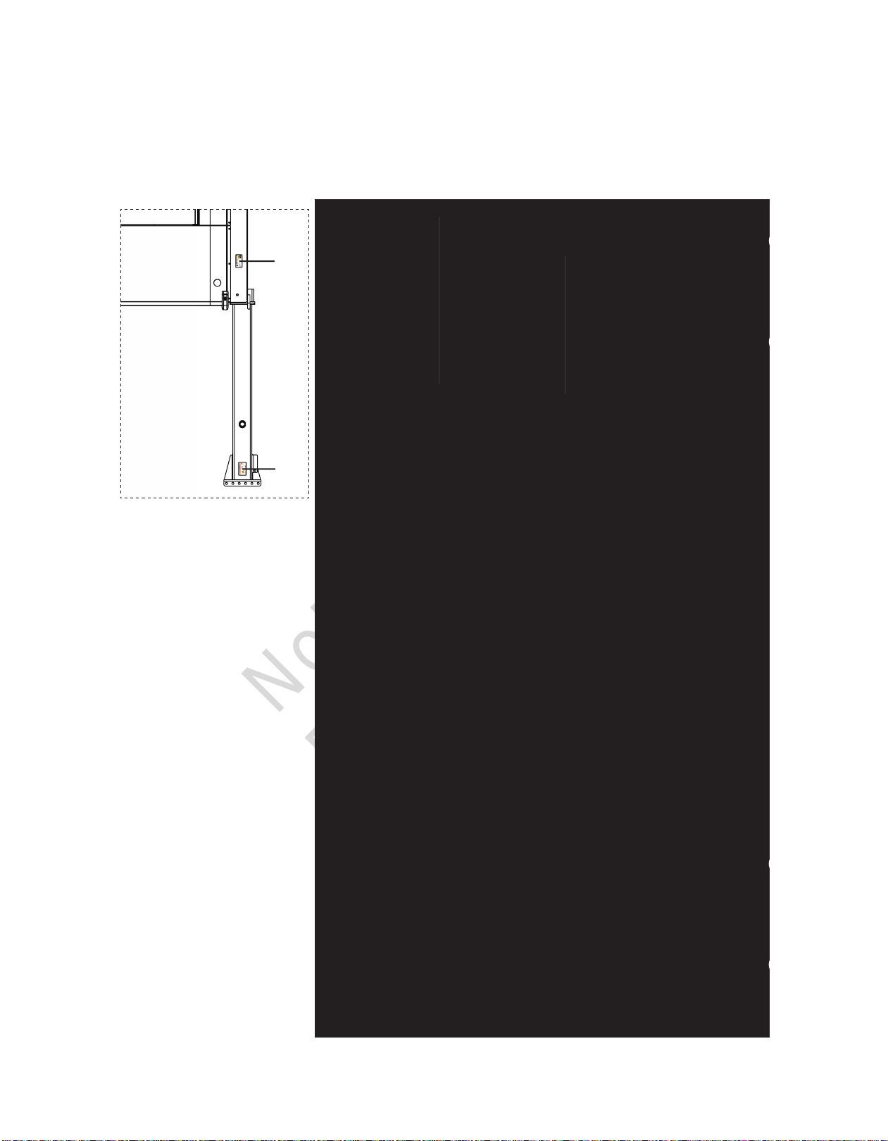
Please indicate the MODEL / SER.No. on the plate of the machine when making inquiries.
A plate stamped with the model and serial number is attached to the side of the machine.
Each illustrated figure (Fig.) has a number
(for instance, A130375) at the right bottom.
This number is not a part number, but it is used only for
our reference number.
A130375
A VIN plate is also located on the left side of the machine.

Not for
Reproduction
6 ALLMAND.COM
Operator Safety
S-3
Safety Warning Labels
The following safety warning labels are attached to the machine. If damaged or missing, contact your
dealer for replacements.
A
BCD
E
F H I
J K LM N
O
P
G
R
Q
E1
Not for
Reproduction
7
Operator Safety
S-4
Location of safety warning labels
A180276E
G
F
E
BC D
L
M
N
O
H
I
A
P
Receiver tank portion sticking position
Shroud portion sticking positi
on
K
J
Operator Safety
S-4
Location of safety warning labels
A180276E
G F E
B C D
L
M
N
O
H
I
A
P
Receiver tank portion sticking position
Shroud portion sticking positi
on
K
J
R
Q
E1 E1 E1 E1
Not for
Reproduction
8 ALLMAND.COM
Operator Safety
S-5
Compressed air from this machine contains poisonous
materials. Absorption of the compressed air can cause
serious injury. Never provide this compressed air for human
respiration.
This machine is not designed to be used for working
chambers pressurized by compressed air such as
respiratory air provided to persons working inside wells and
tunnels such as pneumatic engineering method and
pneumatic caisson method. Should this machine stop
operation due to trouble, it can cause death and serous
injury to the working persons. Refrain from using the
compressed air for such pneumatic engineering method or
pneumatic caisson method.
Read each instruction plate which is displayed in the
manual or on the machine carefully, understand its content
and follow the indications thereof.
Do not modify the machine without prior approval. The
safety may be compromised, functions may be
deteriorated, or the machine life may be shortened.
Never use the machine for the purpose of compression of
gases other than air, or as a vacuum pump. Otherwise,
serious accidents may occur.
Never blow compressed air directly at people. Scattered
impurities, dust, or foreign objects in the compressed air
may cause skin and eyes to be seriously injured.
As compressed air contains toxic gas etc., compressed air
should not be used to be blown or sprayed against food
etc.
Keep hands off from the rotating portion or belts while
running. It could cause serious injuries if hands should be
caught in.
TR0201-1
A080001
TR0086
TR0092
TR0304

Not for
Reproduction
9
Operator Safety
S-6
As part of pre-start safety checks, always confirm that there
is no residual pressure in the tank by carefully opening the
service valve, even if the pressure gauge on the screen
indicates 0PSI.
Note residual pressure in the separator receiver tank could
force both extremely hot compressed air and oil to jet out
and you may be scalded or seriously injured.
W011

Not for
Reproduction
10 ALLMAND.COM
Operator Safety
S-7
When cleaning dust accumulated in such devices as the
air-filter, by blowing compressed air, wear safety glasses,
etc. to protect your eyes.
Be sure to stop the engine, and let the coolant water
sufficiently cool down before draining it.
If the drain valve is opened before the coolant water is
cooled enough, hot water could jet out, and it could cause
scalding.
Be sure to perform the periodic checks of compressor oil
and oil separator.
Neglecting checks could cause overheat of the oil, resulting
in a fire.
Waste liquid from the machine contains harmful material.
Do not discharge it onto the ground or into the river, lake or
sea. Such material will contaminate the environment.
Be sure to use a container to hold the waste liquid from the
machine.
Be sure to follow the designated regulations when
disposing of oil, fuel, coolant (antifreeze), filter, battery or
other harmful materials.
The engine of this machine and electrical parts many electronic devices have been
installed. If you perform welding work, remove the connector of the electronic control
equipment. Application of excessive current to electronic controls can cause
equipment malfunction.
M003
H990432
W004-1
A100285

Not for
Reproduction
11
Features and Controls
1-1
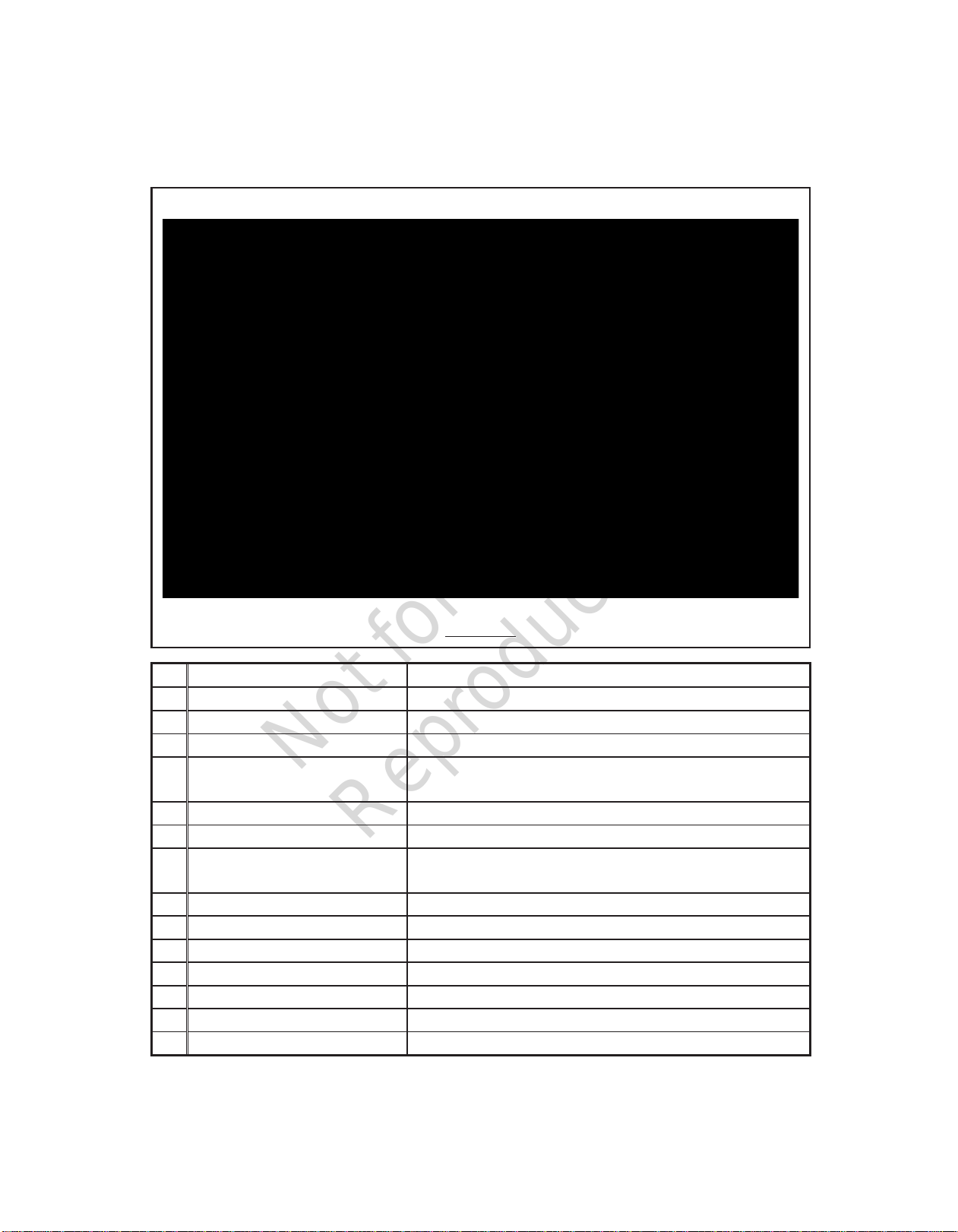
Internal Components
A180429
No.
Description
Function
A Safety valve
For releasing compressed air to the atmosphere when the pressure rises higher
than the rated pressure in the system.
B
Air filter (For compressor air-end)
Filtering device for filtering dust floating in intake air.
C
Air filter (For engine)
Filtering device for filtering dust floating in intake air.
D
Sedimenter
For separating coolant from fuel in the system.
E
Fuel pre-filter
For removing dust and water mixed in fuel.
F
Fuel filter
For filtering foreign matter and dust mixed in fuel.
G
Fuel air-bleeding electromagnetic pump
For automatically bleeding air from fuel pipes in the system.
H
Reserve tank
For checking coolant level and supplying it.
I
Compressor oil filter
For filtering compressor oil in the system.
J
By-pass valve
For keeping compressor oil at optimum temperature in the system.
K
Oil cooler
For cooling compressor oil in the system.
L
Fuel tank drain valve
For draining condensates from fuel tank.
M
Fuel tank
For storing fuel.
N
Engine oil filler port
For supplying and replenishing engine oil to engine.
O
Engine oil filter
For filtering engine oil in the system.
P
Engine oil level gauge
For checking engine oil level.
Q
Separator receiver tank
For separating air and oil from compressed air in the system.
R
Separator receiver tank drain valve
For draining condensed water from separator receiver tank.
S
Compressor oil filler port
For supplying or adding compressor oil.
T
Compressor oil level gauge
For checking compressor oil level.
A B C D E F G H I J K
T S R Q P O N M L
MA400 T4F
Features and Controls
Not for
Reproduction
12 ALLMAND.COM
Features and Controls
1-2
A180430
MA400 T4F
No.
Description
Function
A
SCR (Selective Catalytic Reduction)
Selective reduction-type catalyst that uses DEF as a reducing agent.
B
Radiator
For cooling the coolant for engine in the system.
C
Engine
For driving the compressor air-end in the system.
D
Solenoid valve for unloader spring
chamber
For reducing loads during start-up.
E
Pressure regulator
For controlling full load and unload operation.
F
Solenoid valve for starting unload
For reducing load at start-up.
G Pressure control valve
For keeping the pressure in receiver tank constantly higher than a certain level in
the system.
H
Compressor air-end
For compressing air in the system.
I
Battery
For electrically starting engine.
J
DEF tank
Container for DEF
K
Engine oil drain valve
For draining engine oil.
L
Oil cooler drain valve
For draining compressor oil from oil cooler and oil line.
M
Radiator drain valve
For draining engine coolant.
N
DPF (Diesel Particulate Filter)
Apparatus for removing harmful components contained in the exhaust gas.
A B C D E F G H
N M L KJI

Not for
Reproduction
13
Features and Controls
1-3
A180431
MA375-DP T4F
No.
Description
Function
A
SCR (Selective Catalytic Reduction)
Selective reduction-type catalyst that uses DEF as a reducing agent
B
Radiator
For cooling the coolant for engine in the system
C
Engine
For driving the compressor air-end in the system
D
Solenoid valve for unloader spring
chamber
For reducing loads during start-up
E
High pressure regulator
Pressure regulator used to control air pressure during high pressure operation
F Pressure switching solenoid valve
Equipment for switching the operating pressure between low pressure and high
pressure
G
Low pressure regulator
Pressure regulator used to control air pressure during low pressure operation
H
Solenoid valve for starting unload
For reducing load at start-up
I Pressure control valve
For keeping the pressure in receiver tank constantly higher than a certain level in
the system
J
Compressor air-end
For compressing air in the system
K
Battery
For electrically starting engine
L
DEF tank
Container for DEF
M
Engine oil drain valve
For draining engine oil
N
Oil cooler drain valve
For draining compressor oil from oil cooler and oil line
O
Radiator drain valve
For draining engine coolant
P
DPF (Diesel Particulate Filter)
Apparatus for removing harmful components contained in the exhaust gas
A B C D E F G H I J
P O N MLK
Not for
Reproduction
14 ALLMAND.COM
Features and Controls
1-4
After cooler type
Only options available on standard units are shown in the following figure.
No.
Description
Function
1
Drain separator
For separating water from compressed air cooled through after cooler
2
After cooler
For cooling compressed air
3
Drain port of air pipe
For draining condensate from drain separator
4 Drain warming valve
For preventing freezing of water separated through drain separator when
exhausting it
A180431
D C B A
Not for
Reproduction
15
Set-Up and Installation
2-1
Transportation
When loading and unloading the machine, make sure to use the lifting bail provided on the center of the
machine top.
Lifting
1. Before lifting the machine, make sure to check the lifting
bail [A] for any cracks or loosened bolts.
2. Connect the hook [B] of the crane or shackle to the
lifting bail eye fitted at the top center of the machine.
Make sure there is no person standing around the
machine. Then perform the hoisting operation.
3. Select a truck or a crane with a capacity sufficient for the
size and weight of the machine. See “Specifications.”
4. Any crane operations must be performed by a qualified
crane operator.
Mounting the machine on a truck bed
Fasten the machine with ropes [A] as shown, and
securely fix it on the truck bed.
Place one set of chocks [B] against the wheels. Pull the
parking brake lever firmly after the machine is loaded on
the truck bed.
Never stand under the machine when lifted. Death or serious injury could result.
Lifting the machine while still in operation could result in death or serious injury, or
serious equipment damage.
Transportation warnings
A160749
A160750
A
B A
B
A
Lifting bail
Set-Up and Installation

Not for
Reproduction
16 ALLMAND.COM
Set-Up and Installation
2-2
Towing
Before towing the machine, make sure to check the following:
Proper tire pressure.
Tire lug nuts are not loose.
Tires are not worn or damaged.
Make sure that the end of the drawbar is securely connected to the coupler of the
towing vehicle, to prevent disconnection while the machine is being towed.
Make sure there is no damage to the towing vehicle or the drawbar of the machine.
Make sure to keep your hands away from any part of the coupling device when
coupling or uncoupling.
Make sure to drive the towing vehicle safely. Avoid dangerous situations or
conditions on the road.
Failure to obey the above instructions could result in death or serious injury, or
serious equipment damage.
Warnings for towing the machine
Not for
Reproduction
17
Set-Up and Installation
2-3
Installation conditions
The machine must be parked on a firm, level surface.
The machine must be parked perpendicular (on a right angle) to a slope.
The machine must not be parked on a slope more than 15°
The machine should be operated in the following conditions:
Ambient temperature-------------- -5°F to 104°F (-15℃to +40℃)
Humidity------------------------------ Less than 80%
Altitude--------------------------------
Lower than1,500m above sea level
Operating the machine in conditions other than those stated above could result in death or serious
injury, or serious equipment damage.
The machine must be installed in an environment where fresh air is always available. Avoid temperature
extremes and excessive humidity.
If more than two machines are placed together in operation, keep enough distance so that the exhaust
from one machine does not affect the other.
Keep enough space around the machine for inspection and maintenance access.
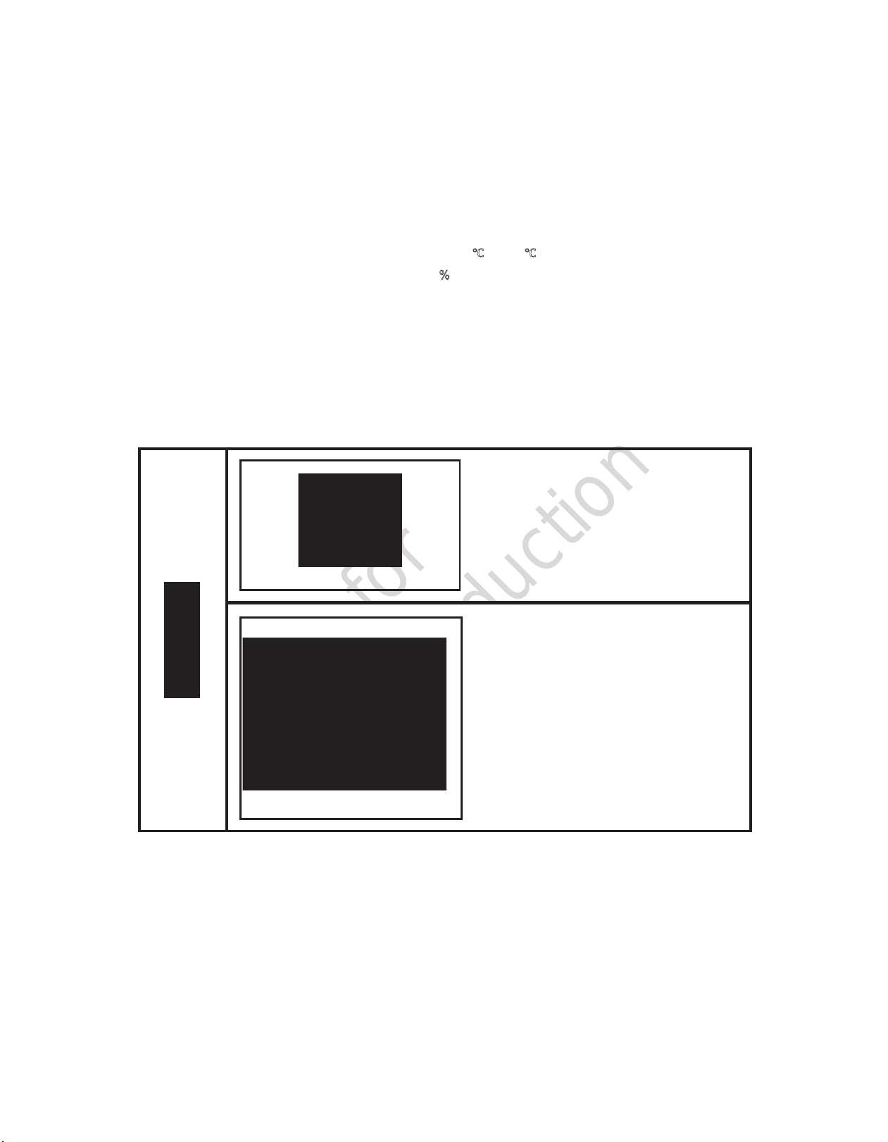
Exhaust gas from the engine is poisonous. It
could cause death or serious injury if inhaled.
Avoid using the machine in an insufficiently
ventilated building or tunnel.
Do not position the exhaust gas outlet in
direction of a person or a house.
When installing the machine in a tunnel or
other enclosed space, make sure to provide
a supply of fresh air and adequate ventilation.
Make sure to install an exhaust pipe that
leads to an outdoor location. Make sure to
check any seams in the exhaust pipe for
leaks.
Do not position the exhaust gas outlet in the
direction of a house.
Exhaust from the engine is harmful. Avoid
positioning it in the direction of passers-by.
PC002
A150835
Exhaust pipe
Use an air blower
for taking in air
○
Exhaust gas
×
A150836
○
×
Private house
Set-Up and Installation
2-3
Installation conditions
The machine must be parked on a firm, level surface.
The machine must be parked perpendicular (on a right angle) to a slope.
The machine must not be parked on a slope more than 15°
The machine should be operated in the following conditions:
Ambient temperature-------------- -5°F to 104°F (-15℃to +40℃)
Humidity------------------------------ Less than 80%
Altitude--------------------------------
Lower than1,500m above sea level
Operating the machine in conditions other than those stated above could result in death or serious
injury, or serious equipment damage.
The machine must be installed in an environment where fresh air is always available. Avoid temperature
extremes and excessive humidity.
If more than two machines are placed together in operation, keep enough distance so that the exhaust
from one machine does not affect the other.
Keep enough space around the machine for inspection and maintenance access.
Exhaust gas from the engine is poisonous. It
could cause death or serious injury if inhaled.
Avoid using the machine in an insufficiently
ventilated building or tunnel.
Do not position the exhaust gas outlet in
direction of a person or a house.
When installing the machine in a tunnel or
other enclosed space, make sure to provide
a supply of fresh air and adequate ventilation.
Make sure to install an exhaust pipe that
leads to an outdoor location. Make sure to
check any seams in the exhaust pipe for
leaks.
Do not position the exhaust gas outlet in the
direction of a house.
Exhaust from the engine is harmful. Avoid
positioning it in the direction of passers-by.
PC002
A150835
Exhaust pipe
Use an air blower
for taking in air
○
Exhaust gas
×
A150836
○
×
Private house
Not for
Reproduction
18 ALLMAND.COM
Set-Up and Installation
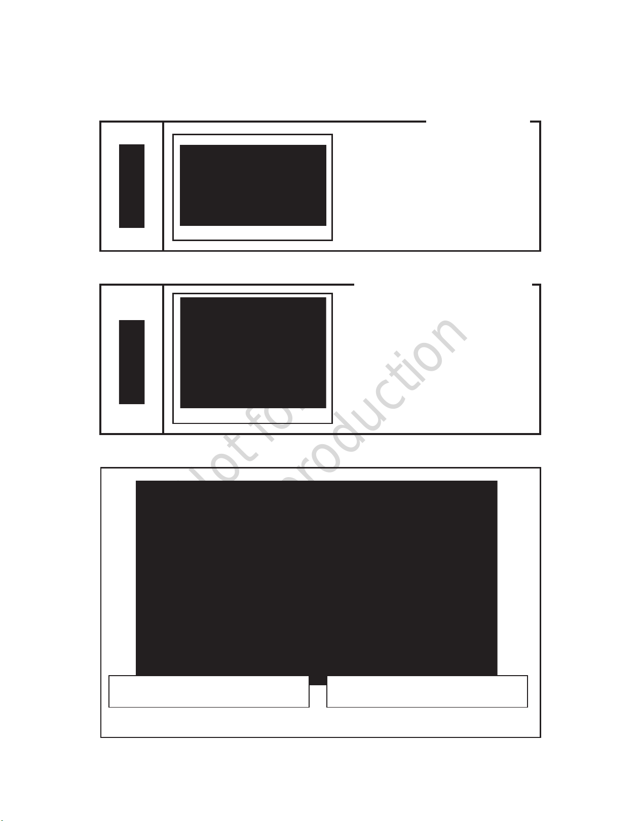
2-4
Make sure to install wheel chocks [A] on both
sides of both tires. Failure to do so could
result in death or serious injury.
Make sure to place a safety fence around the
machine, to prevent unauthorized access to
the machine.
Service valve
A160694
A160751
A
安全护拦
Installation notes
Placing safety fence in position
A120199
Safety fences
Bore of service valve: 20A(R3/4B)×2
[Taper male screw]
Bore of service valve: 50A(Rc2B)×1
[Taper female screw]

Not for
Reproduction
19
Set-Up and Installation
2-5
Piping or air hoses connected to the service
valves of this machine must meet or exceed
the discharge pressure of the machine.
Connect piping or air hoses to the service
valves of this machine firmly before operation,
and check during operation. A loose
connection could separate and result in death
or serious injury.
Close the service valves and relieve
remaining pressure before removing piping or
air hoses. Remaining pressure in the piping
or air hoses could result in death or serious
injury.
Read the operator manuals supplied with any
tools or equipment used in conjunction with
this machine.
Do not operate the machine with service
valves and relief valve open unless
connected to piping or air hoses.
High-pressurized air directly from the service
vales could result in death or serious injury.
If the machine must be temporarily operated
with the valve open, mount a silencer to
reduce noise, and wear hearing protection to
prevent hearing damage.
A partially open service valve could result in
equipment damage and air leaks. Make sure
the service valve is fully closed or fully open.
A150841
○
○
×
Partially open
Fully closed Fully open
Cautions of service valve
TR0088
Warnings of hose attachment and removal
TR0303A
Operation with discharge port
(compressed air supply port) opened is prohibited
D003
Not for
Reproduction
20 ALLMAND.COM
Operation
3-1
Instrument Panel
Each display of the operation panel is illustrated as follows.
Read and fully understand the explanations and be sure to operate safely:
A180427
[START] button
Start operation by holding
the button for 1 second.
[CONTROL POWER] switch
Switch to start and stop
the unit.
Switch to change high pressure
mode and low pressure mode.
Touch Screen
Display operation conditions
and set each parameter.
PRESSURE SELECTOR switch
(MA375-DP T4F only)
Operation
This manual suits for next models
1
Table of contents
Other Allmand Air Compressor manuals


Popular Air Compressor manuals by other brands


SMC Networks
SMC Networks CRP10 Series Operation manual

Bambi
Bambi VT75 Operator's handbook

Stanley
Stanley DN 200-10-5 instruction manual

ULTIMATE SPEED
ULTIMATE SPEED UMK 10 C2 Operation and safety notes translation of the original instructions

Powermate
Powermate S0200412 parts manual

MODE
MODE HS08-6 Series instruction manual

Parkside
Parkside PKO 400 A1 operation and safety notes original operating instructions

Campbell Hausfeld
Campbell Hausfeld Vertical Operating instrctions

Bitzer
Bitzer ST-150-2 technical information

RAMVAC
RAMVAC OSPREY Maintenance chart

California Air Tools
California Air Tools 4610AC-22050 owner's manual

darda
darda BP2 product manual