Alloy Maxhub C65FA User manual

1
C65CA-BO9072D-M
Service Manual V1.0

2
Document Revision History
Version
Modification
Date
Page
NO.
Updated Instructions
Reviser
Confirmed
by
1.0
9/19/2020
All
Release Version
Hooke
Lin
Yiqingduo

3
CONTENT
Safety Instructions...............................................................................................................................4
I. Safety warning..................................................................................................... 4
II. Notice................................................................................................................. 5
Product Basic Specifications................................................................................................................6
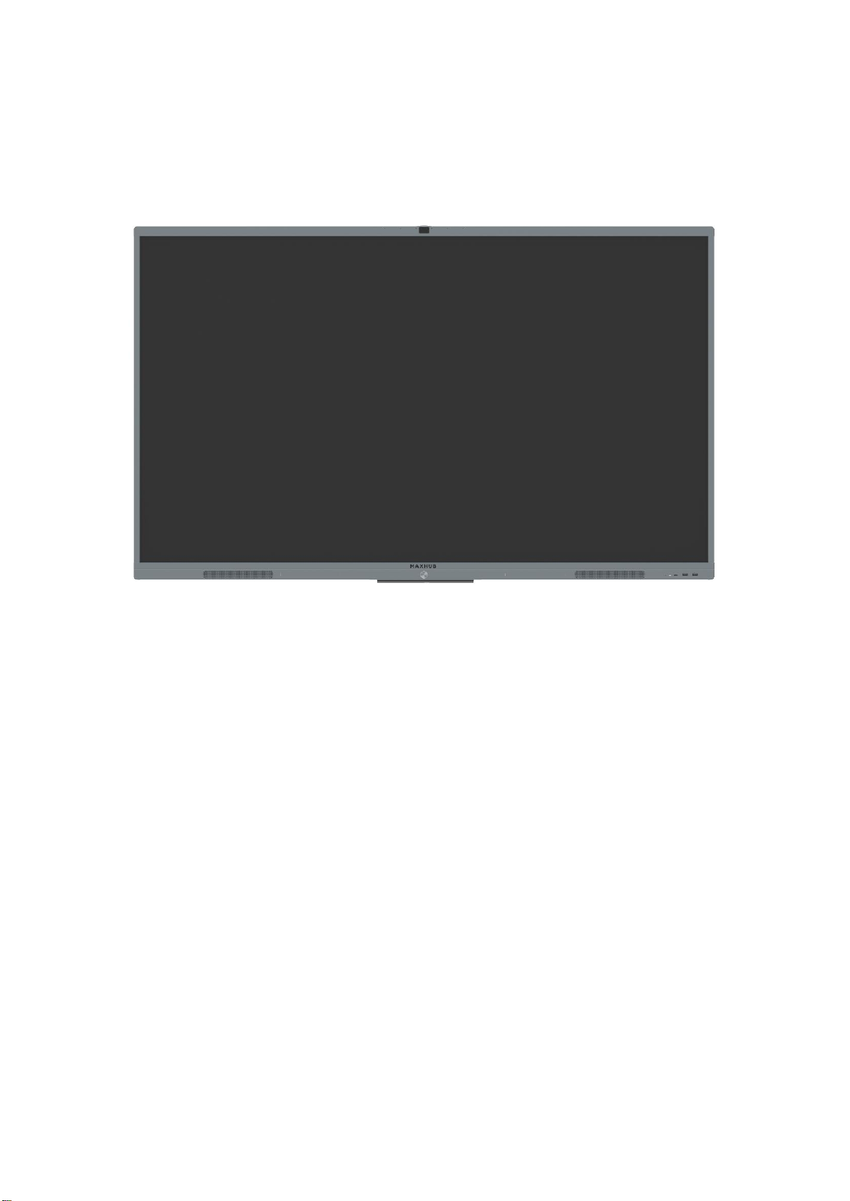
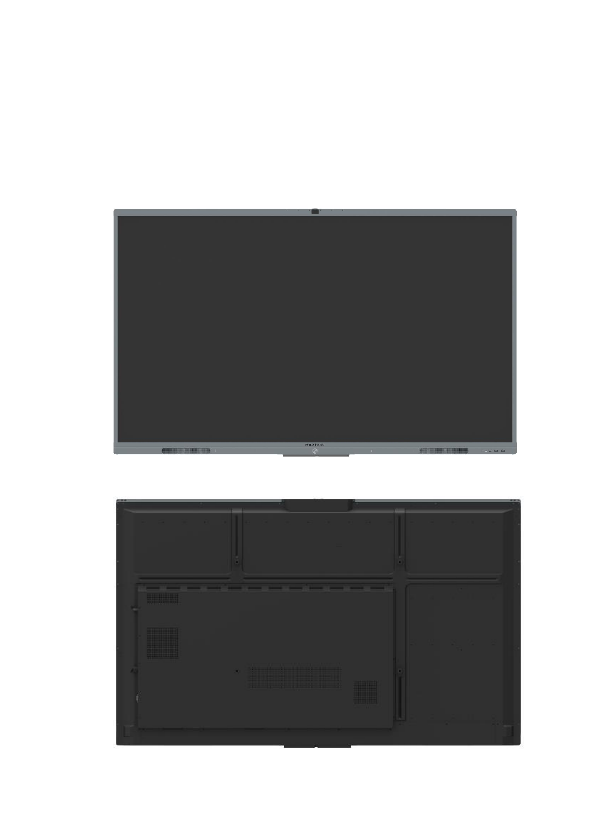
I. Product Appearance............................................................................................6
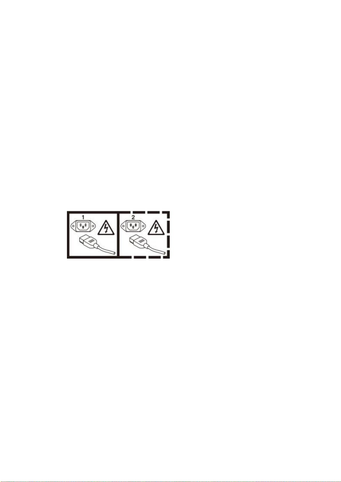
Electrical Diagram................................................................................................................................9
Disassembly guide.............................................................................................................................10
I. Exploded Views..................................................................................................10
II. Shell Disassemble............................................................................................. 11
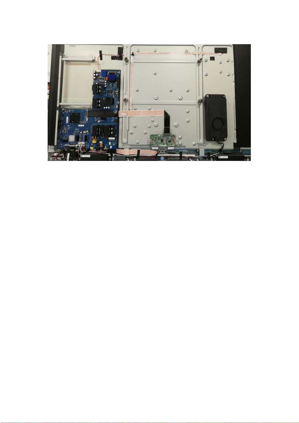
III. Circuit Boards Disassemble............................................................................. 11
IV. Touch Frame Disassembly............................................................................... 16
Internal Cables...................................................................................................................................18
I. Cable Connection Guide....................................................................................18
II. Cable Connection Diagram...............................................................................19
Key Parts List (For reference only).....................................................................................................22
Principle of Key Components............................................................................................................ 23
I. Three-in one Main Board (TP.T972.360W)........................................................ 23
II. Wifi Board (SRV.AP_WiFi_IoT.01)..................................................................... 27
III. Touch Frame(X65G03)..................................................................................... 28
Troubleshoot steps............................................................................................................................ 30
I. LED does not turn red........................................................................................30
II. LED does not turn blue.....................................................................................31
III. Touch issue...................................................................................................... 32
IV. PC issue............................................................................................................33
V. LED turn blue but no backlight......................................................................... 34
Firmware update procedure............................................................................................................. 35
I. Upgrade All (TV & MCU)....................................................................................35
II. Touch frame Update......................................................................................... 36

4
Safety Instructions
Please read the safety information carefully before installing, maintaining, or
disassembling this product.
I. Safety warning
The current of power supply, telephone and communication cable is dangerous
and the on/off button, power switch on the device do not cut off the current
completely. To avoid the danger of electric shock:
Be aware that the device may have several power supply cables at the same time.
To cut off the power, make sure all power supply cables are disconnected.
Do not connect or disconnect any cables, install, maintain, or reset the product
during thunderstorm.
Connect all power cables to the right and use the well grounding power supply
socket.
Connect all devices to the proper connector.
Connect or disconnect cables with one hand is recommended.
Do not turn on any device when there is a fire, flood, or collapse of a house.
Please disconnect the power cable, remote communication system, network,
modem, and other devices before opening the screen, unless otherwise
specified in the installation and configuration process.
When the product is installed, moved or opened, the step of cable connection or
disconnection is provided as below.
To connect cables:
1. Turn off all devices.
2. Connect power cords to devices.
3. Connect signal/ communication
cables to devices.
4. Connect the power cord to power
supply socket.
5. Turn on devices。
To disconnect cables:
1. Turn off all devices.
2. Unplug power cords from the
socket.
3. Disconnect signal
/communication cables from
connector.
4. Disconnect the power cords from
devices

5
II. Notice
1. When replacing the system battery, please use the same kind of battery.
2. Battery containing lithium, improper operation or handling will cause explode.
Please DO NOT:
Put the battery into water
Heat the battery to more than 100 degrees C (212 degrees F)
Repair or disassemble the battery without authorization
3. The AC switch or button mightn't cut off the AC power supply, Please disconnect
the AC cable if you need.
4. Do not remove any cover of the module with the danger label attached.

6
Product Basic Specifications
I. Product Appearance
Front view
Back view

7
Side view
PC Module
Right side signal input/output
AC insert and switch

8
Back view of the screen
Three-in-one main board
TCON
Woofer
USB board
Key board WiFi board
Speaker
Speaker

9
Electrical Diagram

10
Disassembly guide
I. Exploded Views
NO.
NAME
QTY
NO.
NAME
QTY
1
AG Glass bracket(Upper,Middle)
1
21
Side terminal bracket
1
2
Upper bezel
1
22
Three-in-one main board
1
3
Left external upper corner
1
23
TCON
1
4
Left inside upper corner
1
24
WiFi board
1
5
AG Glass bracket
2
25
Small back cover(Left)
1
6
AG Glass
1
26
Small back cover(Middle)
1
7
Touch frame
1
27
Panel pressing block
2
8
Left bezel
1
28
Small back cover(Right)
1
9
Key board
1
29
Big cover
1
10
AG Glass bracket(Upper)
4
30
Camera & MIC board
1
11
Left external bottom corner
1
31
Camera & MIC cover
1
12
Left inside bottom corner
1
32
Camera cover
1
13
AG Glass bracket(Bottom)
1
33
Camera
1
14
USB board
1
34
Woofer
1
15
Bottom bezel
1
35
Backlight
1

11
II. Shell Disassemble
1. Screw Location
III. Circuit Boards Disassemble
1. Screw Location
Three-in-one Main Board
NO.
NAME
QTY
NO.
NAME
QTY
16
Magnet
2
36
Right external bottom corner
1
17
PC module
1
37
Right inside bottom corner
1
18
PC module bracket(upper)
1
38
Right bezel
1
19
PC module bracket(bottom)
1
39
Right inside upper corner
1
20
Speaker
2
40
Right external upper corner
1

12
USB Board
(1) Take off the screws of USB board bracket
(2) Take out the plastic components and USB board

13
Hall device
Key Board

14
Camera & MIC Board
2. Maintenance Description
▓To replace the circuit boards you need to remove first the rear covers and wires.
▓To replace the TV main board, you need to remove the lower terminal block, the
side terminal block.
▓Cut off the power before performing replacement, so as to prevent any short
circuit resulting from contact of wires.

15
Please note whether the ports of the cables are properly connected in order to
prevent the component from being burnt due to inserting in the wrong ports.

16
IV. Touch Frame Disassembly
STEP 0: Get machine from the movable bracket and lie it down on the table( Be
careful on protection)
STEP 1: Remove small back board(Left/middle/right)
STEP 2:Remove external corner
STEP 3: Remove the touch cables between touch frame and Three-in-one main board,
use tweezers to press the buckle of touch cable connector and plug out the cable by
hands.
STEP 4: Remove corners
STEP 5: Plug out the FFC cables of below position: Top left、bottom left、bottom right
joint point of touch frame

17
STEP 6: For top and bottom touch frame: Push the touch board from one side and
pull out the board by hands from the other side
For left and right touch frame: Push the touch board from bottom side and pull out
the board by hands from the top side
STEP 7:Completed
FFC socket
Three PCBA on the corners are connected
with 150mm FFC cables
FFC socket

18
Internal Cables
I. Cable Connection Guide
Part Name
Part No
Cable Connection Guide
1.FFC Cable 1
004.050.0004743
Three-in-one main board to TCON board
2.FFC Cable 2
004.050.0050130
Three-in-one main board to WiFi board
3.FFC Cable 3
004.050.0050208
Three-in-one main board to Camera
4.FFC Cable 4
004.050.0004746
Camera to MIC
5.FFC Cable 5
004.050.0004747
Camera to MIC
6.speaker cable
004.050.0050014
Three-in-one main board to speaker
7.USB cable
004.050.0050005
Three-in-one main board to USB board
8.Touch frame FFC cable
004.050.0003249
Three PCBA on the corners are connected with
150mm FFC cables

19
II. Cable Connection Diagram
1~5. FFC Cable 1~FFC cable 5
6.Speaker cable
Camera & MIC board
FFC cable 5
FFC cable 4
FFC cable 1
FFC cable 2
FFC cable 3

20
7. USB cable
8.Touch frame FFC cable(Three PCBA on the corners are connected with 150mm FFC
cables)
This manual suits for next models
1
Table of contents
Other Alloy Flat Panel TV manuals
Popular Flat Panel TV manuals by other brands

Philips
Philips 32PFL6704D - 32" LCD TV user manual

Philips
Philips 37PF7321/98 Specifications

Insignia
Insignia NS-L322Q-10A - 32" LCD TV user guide

Sony
Sony KDL-40EX500 - Bravia Ex Series Lcd... Specifications

Samsung
Samsung LT-P2045U Manual de instrucciones

Magnavox
Magnavox 42MF130A - 42mf130a/37 Guide de l'utilisateur