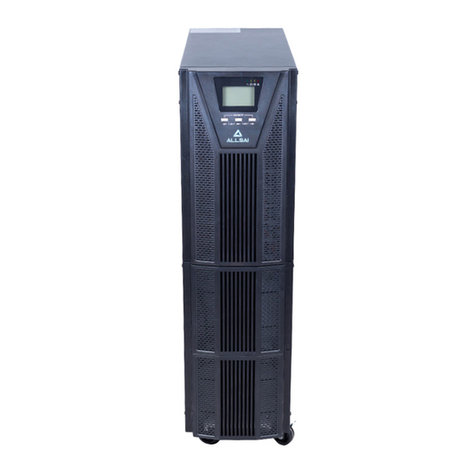
Allsai 10 kVA User manual


1
Table of Contents
1Safety Information ............................................................... 2
2Product Overview ................................................................ 4
2.1 Specifications ..............................................................................4
2.2 Front panel features....................................................................6
3Installation............................................................................ 8
3.1 Unpacking inspection..................................................................8
3.2 Single System Installation ...........................................................8
3.3 Parallel System installation .......................................................11
4Operation Instructions ...................................................... 15
4.1 Display panel .............................................................................15
4.2 UPS settings...............................................................................19
4.3 Parameters inquiry....................................................................29
4.4 Event log query .........................................................................30
4.5 UPS On / Off operation .............................................................31
4.6 Connect the communication.....................................................32
4.7 Parallel UPS operation ..............................................................35
5Operation Modes................................................................ 36
5.1 Power-up mode / Shutdown mode ..........................................36
5.2 Standby mode ...........................................................................36
5.3 Bypass mode .............................................................................37
5.4 Mains power mode (Frequency conversion mode) ..................38
5.5 Battery mode / battery self test mode .....................................39
5.6 ECO mode..................................................................................39
5.7 Fault mode ................................................................................40
5.8 Maintenance bypass .................................................................41
5.9 Test mode..................................................................................41
6Troubleshooting................................................................. 42

2
1 Safety Information
CAUTION
Non-qualified electricians are forbidden to open the case due to hazard of
electrical shock.
Consulting the dealer is required before using for below equipment. Its application,
configuration, management and maintenance must be specially considered and
designed.
Medical equipment which is directly related to patients’life
Elevator and other equipment which may endanger personal safety
WARNING
The UPS must be properly earthed / grounded and due to a high leakage current,
the earthing / grounding conductor must be connected first.
Safety and General Information
Read all safety information and operating instructions carefully before
attempting to install, operate, service or maintain the UPS.
The UPS contains internal batteries and may present a shock hazard even
when disconnected from the branch circuit (mains).
The protective earth conductor for the UPS carries the leakage current from
the load devices (computer equipment). An insulated ground conductor is to
be installed as part of the branch circuit that supplies the UPS. The conductor
must have the same size and insulation material as the grounded and
ungrounded branch circuit supply conductors.
Do not use liquid extinguisher if there is a fire, a dry powder extinguisher is
recommended.
Disconnect all connection wiring before maintenance or cleaning to avoid the
risk of electric shock.
Do not dispose of the batteries with fire. The batteries may explode.
Do not open or mutilate batteries. Released electrolyte inside is harmful to the
skin and eyes, and maybe toxic.
Do not connect the positive pole and negative pole directly, otherwise it will
cause electric shocks or will be on fire.

3
It is not suitable to connect some electric equipments such as hair drier and
heating appliance.
Note:Symbol instructions
Symbol
Significations
Symbol
Significations
Caution
Protective earth
Danger! High
Voltage!
Disable/mute audible
alarm
Turn on
Bypass
Turn off
Battery inspection
Standby or
Shutdown
Repeat
AC
Battery
DC

4
2 Product Overview
2.1 Specifications
MODEL
10 kVA
15 kVA
20 kVA
30 kVA
Capacity
10 kVA
/ 9 kW
15 kVA
/ 13.5kW
20 kVA
/ 18 kW
30 kVA
/ 27 kW
INPUT
Nominal voltage
360V / 380V / 400V / 415 Vac three-phase (3Φ+N+PE)
Voltage range
277 ~ 485 Vac (no derating)
190 ~ 277 Vac (linear derating between 50% and 100% load)
Rated frequency
50 / 60 Hz (auto-sense)
Frequency range
40 ~ 70 Hz
Power factor
≥ 0.99
Bypass voltage range
-40% ~ +15% (settable)
OUTPUT
Nominal voltage
360V / 380V / 400V / 415 Vac three-phase (3Φ+N+PE)
(settable)
Voltage regulation
± 1%
Frequency
Synchronized with utility in utility mode;
50 / 60 ± 0.1 Hz in battery mode
Power factor
0.9
Crest factor
3:1
Total harmonic
distortion (THDV)
≤ 2% (linear load); ≤ 5% (non-linear load)
Transfer time
Mains mode to battery mode: 0 ms;
Inverter mode to bypass mode: 0 ms
Inverter overload
capability
102% ~ 125%: transfer to bypass in 10 min;
125% ~ 150%: transfer to bypass in 1 min;
> 150%: transfer to bypass in 0.5 s
BATTERY
DC voltage
Standard model: 240 Vdc; Long time model: 192 Vdc
(192V/216V/240V optional)
Inbuilt battery of
standard model
20*7 AH
40*7 AH
40*9 AH
60*9 AH
SYSTEM
Efficiency
Line mode: ≥ 93%; ECO mode: ≥98
This manual suits for next models
3
Table of contents
Other Allsai UPS manuals


