Alpha Outback Energy AlphaNet DM3 Series Datasheet

AlphaNet™ DM3 Series Transponder Installation Quick Start Guide
AlphaNet™ DM3 Series Transponder

DM3
DM3

DM3X

Overview
DM3 Series Transponder installation and setup is comprised of three basic steps:
1. Installation of the DM3 Series transponder into the power supply, making front panel connections and verifying operation.
2. Setting Options: The DM3 Series transponders are designed for out-of-the-box, “plug and play” operation. Non-default settings such as SNMP trap destination addresses may be required for the Network
Management System (NMS). SNMP trap addresses can be set automatically via the DOCSIS configuration file’s docsDevNmAccessTable per RFC 4639 (IPv4) or through the SNMPv3 Notification settings (IPv6),
while DM3 Series proprietary options may be set through type 11 TLV entries. The SCTE-HMS MIBs may need to be compiled into a MIB browser before it can be used to monitor or set transponder and power
supply parameters. Refer to the DM3 Series Technical Manual for details.
3. Configuring the Network: provisioning the DHCP Server with the transponder’s MAC address and assigning it a DOCSIS configuration file.
These steps can be performed independently of one another. However, configuring the network prior to field installation will allow the installation to be verified while personnel are still on-site. Performing field
installation before network configuration might result in additional field service calls to correct mistakes.

If SNMP traps not received.
Installation / Replacement Procedure

For XM3 units in service, backup battery power will not be available during this procedure.
Before removing the Inverter Module, verify the power supply device address is correct.
The power supply device address must not be set to zero and no two power supplies monitored by a single DM3 Series Transponder can have the same address. Power supplies must have 1, 2, 3, 4 or 5 as an
address.
To verify the power supply’s address, go to the LCD display on the inverter module and enter the “PWR CNFG” menu. Scroll to the “Device Address” menu item and verify the device address is set to something
other than 0 (Zero).
If power supply data will not display.
Removing the Inverter Module:
Service personnel must verify the Inverter Module battery breaker remains in the OFF position until instructed to return the unit to service.

1. Turn off the battery breaker.
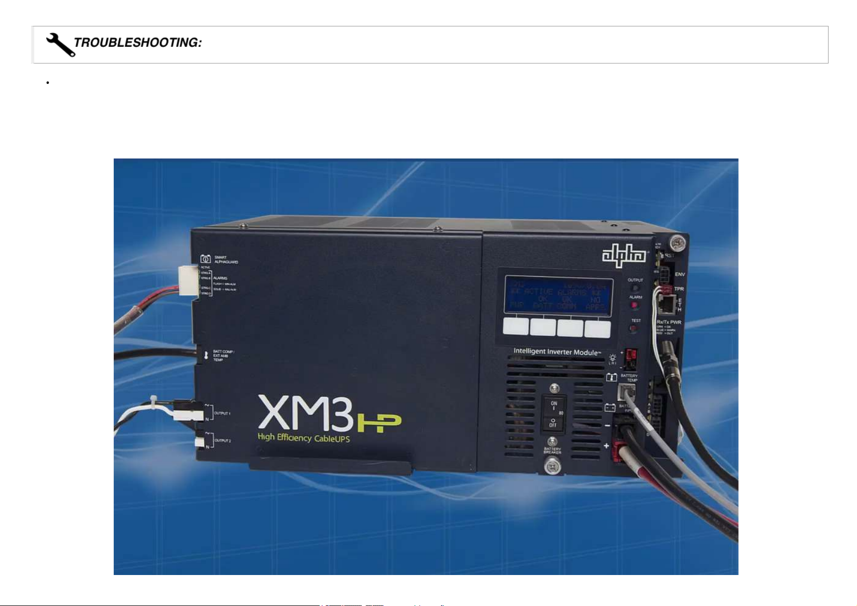
2. Disconnect the battery input and temperature sensor cables from the Inverter Module, followed by the tamper, RF and battery sense cables if a transponder is currently installed.
3. Loosen the thumbscrew on the XM3 Inverter Module and the thumbscrew on the transponder (if applicable).
4. Grasp the handle on the bottom right side of the Inverter Module. Pull firmly to release the module from the inverter connector. Gently slide the module assembly straight out until the Inverter Module is
accessible.
5. If applicable, remove the old transponder from the inverter module.
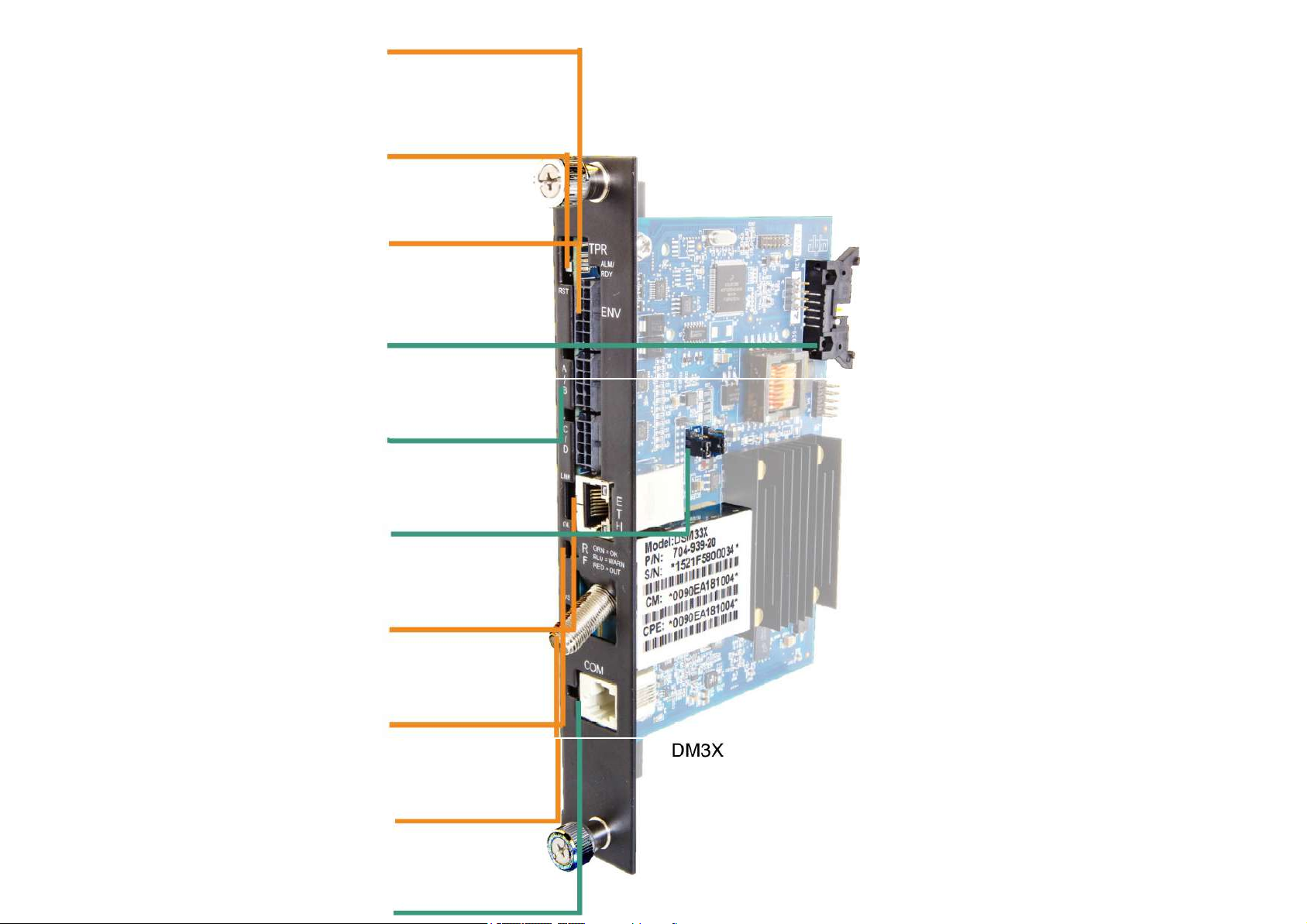
6. Verify the Jumpers (J10 and J11) on the transponder are in the correct position for an XM3 installation.
7. Set the notch at the back of the DM3 Series Transponder onto the white stand-off on the side of the Inverter Module. Then, line up the 18-pin connector on the transponder with the 18-pin socket on the Inverter
Module and connect the two units together
8. Fasten the transponder to the Inverter Module by tightening the two captive screws. It is recommended that the screws be tightened alternately, a few turns at a time, so the transponder aligns in parallel to the
Inverter Module.
When connecting the DM3 Series Transponder to the power supply, ensure that the notch at the back of the DM3 Series Transponder is set on the stand-off on the
side of the Inverter Module. Ensure that ALL 18 pins are lined up to the proper sockets.
9. Reinstall the Inverter Module, tighten the two thumbscrews and reconnect the front panel connections (tamper, temperature sensor, battery harness, etc.).
10. For the DM3X, connect the Battery Sense Wire Kit (not required with Smart AlphaGuard). Refer to the battery diagrams provided with the Sense Wire Kit or reference the DM3 Series Technical Manual (Alpha
p/n 704-939- B0).
11. For the DM3, ensure that the Smart AlphaGuard Wire Kit is connected on the left side of the XM3.
12. Verify the recording of the cable modem MAC address (RF MAC) by navigating to the XM3 Smart Display’s COMM Menu.
13. Connect the RF drop to the transponder. The DOCSIS specification for downstream power level is ± 15 dBmV. However, for optimal performance, set the level as close to 0 dBmV as possible. RF attenuators
or cable simulators may be required to obtain optimal downstream and upstream RF levels.

Using a DM3X in a system configuration with multiple power supplies or AlphaGen generator is optional.
Each power supply must have a unique address other than 0. Refer to Intelligent CableUPS technical manual (p/n 017-882-B0), or the DM3 Series Transponder technical manual (p/n 704-939-B0) for
additional information.
Initial Power-Up and Test / Returning the Unit to Service
1. Verify the power supply is plugged in and powered by utility AC.
2. Switch battery breaker ON.
3. The transponder LEDs will all blink in unison upon initial power up. The RDY LED will then begin blinking steadily indicating normal processor activity.
4. Verify the DS and OL LEDs are on solid. This verifies the Communications Module has registered an IP address on the network.
5. Verify the RF LED is solid Green, indicating Upstream and Downstream Power is within the default specified range and the Upstream RF Power is below the recommended +50 dBmV (Table 1).
6. Verify no XM3 alarms are active.
If the DM3 will not power up.
If the transponder is offline

Test Connection
XM3 Smart Display - COMM Menu
Verify the DM3 Series transponder communication parameters such as IP address, RF Power Levels and Signal/Noise Ratio on the COMM menu of the XM3 Smart Display. Press Enter <ENTR> to open the
COMM- GENERAL Menu enabling the operator to view values for communications parameters. Pressing the up or down arrow softkeys will show two lines of information for each submenu item (click or tap on
the image below to view).
XM3 Smart Display Menu Simulator
Click a softkey to explore its submenus.
Local Web Server Access
You may also test the connection using a computer and a standard Ethernet cable. Connect the computer to the Ethernet port on the transponder, launch an Internet browser (e.g. Internet Explorer) and enter
192.168.100.1 in the address field. The General Configuration page will appear and display connectivity, power levels and power supply status information such as alarms, output voltage, output current and
individual battery voltages. System Name, System Location, System Contact and Common Logical ID may be edited on this page; when prompted for a User Name and Password, use “Alpha” and “AlphaGet”.
If you are configuring a static IP address on Windows 7 or 8, click the Start button (lower left). Once the window pops up, click Control Panel, then Network and Sharing Center, then click the Local Area
Connection, and click the Properties button. In the ensuing dialog box, select Internet Protocol (TCP/IPv4) and click the Properties button. Once the Internet Protocol (TCP/IP) Properties dialog box opens, select
'Use the following IP Address' and enter the IP Address 192.168.100.2 and Subnet mask 255.255.255.0. Click the OK button & try to connect to the DSM3 Series transponder using 192.168.100.1 in your Web
browser.

If the battery voltages will not display.
If laptop is not connecting to webpage.
If the home page of the DM3 Series Transponder does not load using IP address 192.168.100.1, the Local Area Connection on the computer may require a
Temporary Static IP address to be manually configured to 192.168.100.2
Remote Web Server Access
Connect the computer to the cable modem network, launch an Internet browser (e.g. Internet Explorer) and enter the designated transponder IP address in the address field. The General Configuration page will
appear.
DOCSIS RF Levels
Cable Modem Initial Troubleshooting
Cable Modem Troubleshooting
Basic RF Troubleshooting Steps
DOCSIS Resources

AlphaNet™ DM3 Series Transponder Installation Quick Start Guide

Removing the Inverter Module
Initial Power-Up and Test / Returning the Unit to Service
Test Connection
XM3 Smart Display - COMM Menu
Local Web Server Access
Remote Web Server Access
Are you Alpha Academy Certified?
Register for DM3 Series certification (https://alpha.learnupon.com/store)
Contents
Overview
Installation / Replacement Procedure
Worldwide Corporate Offices
Alpha and Outback Energy GmbH reserves the right to make changes to the products and information contained in this document without notice. Copyright © 2020 Alpha and Outback Energy GmbH. All
Rights reserved.
Headquarter Germany
Hansastrasse 8
D-91126 Schwabach
Tel: +49 9122 79889 0
Fax: +49 9122 79889 21
Mail: [email protected]
France and Benelux
fbnl@alpha-outback-energy.com
Spain
For more information please visit www.alpha-outback-energy.com
Russia
russia@alpha-outback-energy.com
Africa
Eastern Europe
Middle East
Table of contents
Popular Marine Radio manuals by other brands

Uniden
Uniden OCEANUS DSC Series owner's manual

DIGITAL YACHT
DIGITAL YACHT AIT2500 Installation and instruction manual

Icom
Icom IC-M802 Notes on operation

GiBiDi
GiBiDi DCX100 Instructions for installations

Smartoptics
Smartoptics DCP-SERIES installation guide

MARINE TECHNOLOGIES
MARINE TECHNOLOGIES Bridge Mate RadaScan Guide

NorthStar
NorthStar VHF Marine Explorer 721EU Operation and installation manual

Uniden
Uniden VHF HH940 operating guide

Raveon
Raveon RV-M7 GX WX quick start guide

Funkwerk
Funkwerk P/N 800ATC-A-(201)-(301) Operation and installation

Uniden
Uniden MC 1010 operating guide

Shakespeare Electronic
Shakespeare Electronic Model SE 700 user manual