Barco MDSC-2226 User manual

User Guide
MDSC-2226


MDSC-2226
User Guide
(451920610993)K5903021/02
01/03/2013

Barco nv
President Kennedypark 35, 8500 Kortrijk, Belgium
Phone: +32 56.23.32.11
Fax: +32 56.26.22.62
Support: www.barco.com/esupport
Visit us at the web: www.barco.com
PrintedinBelgium

Table of contents
TABLE OF CONTENTS
1. Welcome! .......................................................................................... 3
1.1 About the product ............................................................................................. 3
1.2 Symbols........................................................................................................ 4
1.3 What’s in the box.............................................................................................. 4
1.4 About this user guide ......................................................................................... 4
2. Parts, controls and connectors ............................................................... 5
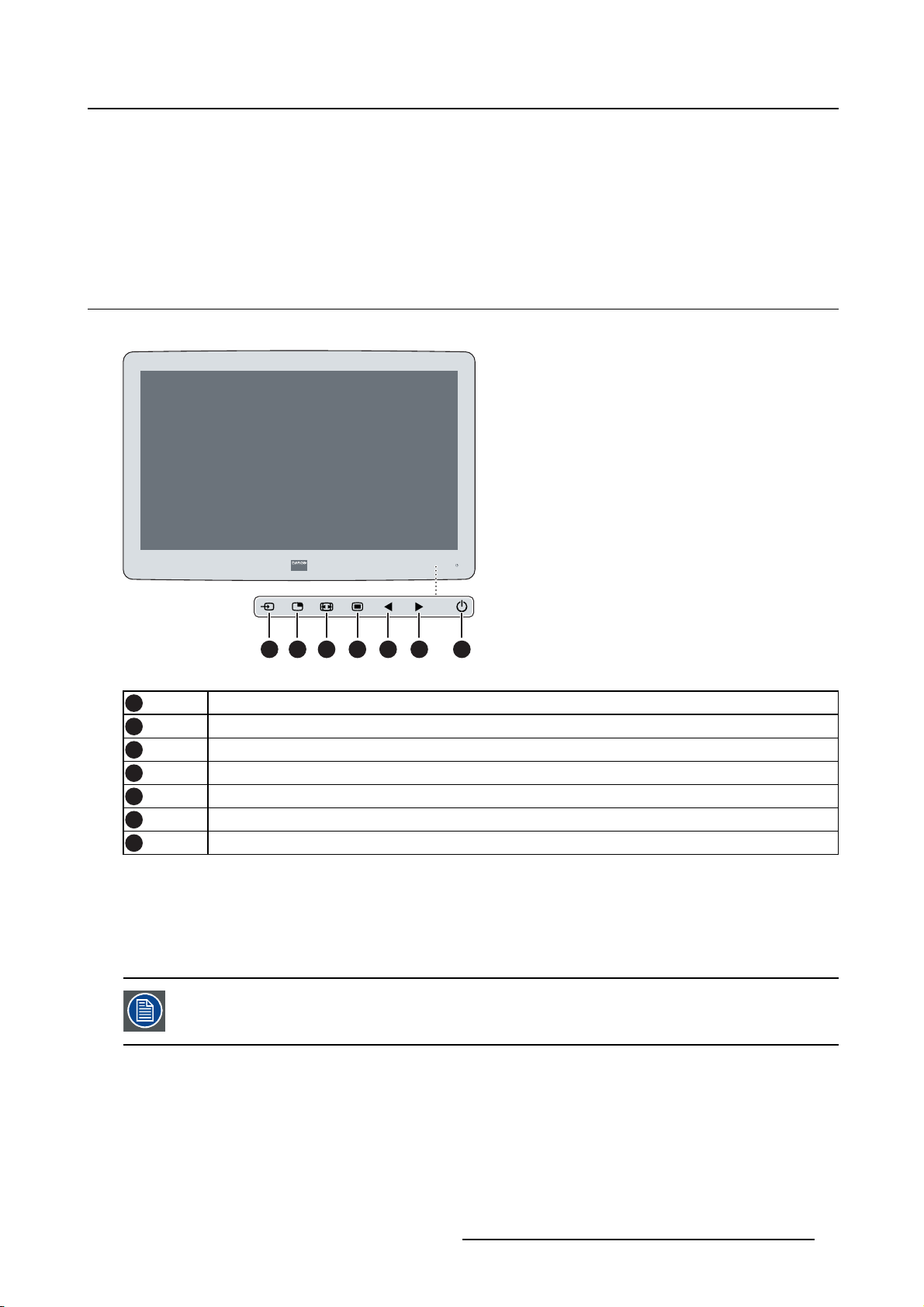
2.1 Front view...................................................................................................... 5
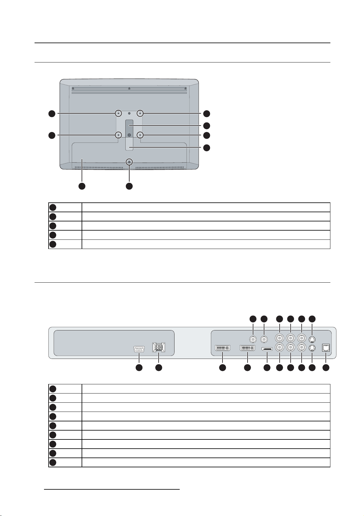
2.2 Rear view ...................................................................................................... 6
2.3 Connector view................................................................................................ 6
2.3.1 MDSC-2226 LED version............................................................................... 6
2.3.2 MDSC-2226 DDI version ............................................................................... 7
2.3.3 MDSC-2226 MNA version.............................................................................. 8
2.4 Connector pin assignments.................................................................................. 9
2.4.1 Input power connector .................................................................................. 9
2.4.2 DVI–1 connector......................................................................................... 9
2.4.3 DVI-2 connector .........................................................................................10
2.4.4 DVI out connector .......................................................................................11
2.4.5 RS232 connector........................................................................................11
2.4.6 USB connector...........................................................................................12
2.4.7 Mini USB connector.....................................................................................12
2.4.8 DisplayPort connector ..................................................................................12
2.4.9 S-Video and S-Video-out connector...................................................................13
3. Display installation .............................................................................. 15
3.1 VESA mount installation......................................................................................15
3.2 Cover removal.................................................................................................16
3.3 Video input connection .......................................................................................16
3.3.1 MDSC-2226 LED version...............................................................................16
3.3.2 MDSC-2226 DDI version ...............................................................................17
3.3.3 MDSC-2226 MNA version..............................................................................17
3.4 Video output connection......................................................................................18
3.4.1 MDSC-2226 LED version...............................................................................18
3.4.2 MDSC-2226 DDI version ...............................................................................19
3.4.3 MDSC-2226 MNA version..............................................................................20
3.5 Nexxis OR .....................................................................................................20
3.6 Power supply connection.....................................................................................20
3.7 Cable routing ..................................................................................................21
4. Daily operation ................................................................................... 23
4.1 Keyboard backlight ...........................................................................................23
4.2 On/Off switching...............................................................................................23
4.3 OSD menu activation.........................................................................................23
4.4 OSD menu navigation ........................................................................................24
4.5 Shortkey functions ............................................................................................25
4.5.1 Main source selection...................................................................................26
4.5.2 Multi-image configuration...............................................................................26
4.5.3 Zoom factor selection ...................................................................................26
4.5.4 Brightness adjustment ..................................................................................26
4.6 Extended keyboard functions................................................................................27
4.6.1 Main source selection...................................................................................28
4.6.2 Second source selection................................................................................28
4.6.3 Multi-image configuration...............................................................................29
4.6.4 Transfer function selection .............................................................................29
4.6.5 Image size selection ....................................................................................29
4.6.6 Zoom factor selection ...................................................................................30
4.7 Keyboard locking/unlocking..................................................................................30
(451920610993)K5903021 MDSC-2226 01/03/2013 1

Table of contents
5. Advanced operation ............................................................................. 33
5.1 OSD picture menu ............................................................................................33
5.1.1 Profile.....................................................................................................33
5.1.2 Brightness................................................................................................33
5.1.3 Contrast ..................................................................................................34
5.1.4 Saturation ................................................................................................34
5.1.5 Color temperature.......................................................................................34
5.1.6 Gamma...................................................................................................35
5.1.7 Sharpness................................................................................................35
5.2 Picture Advanced menu......................................................................................36
5.2.1 Black Level...............................................................................................36
5.2.2 Smart Video..............................................................................................36
5.2.3 Image Position...........................................................................................36
5.2.4 Auto Adjustment.........................................................................................37
5.2.5 Phase.....................................................................................................37
5.2.6 Clock/Line................................................................................................37
5.3 Display Format menu.........................................................................................38
5.3.1 Main Source (Primary Source).........................................................................38
5.3.2 Component Mode .......................................................................................38
5.3.3 Zoom......................................................................................................39
5.3.4 Image Size ...............................................................................................39
5.3.5 2nd Picture Mode ........................................................................................40
5.3.6 2nd Picture Source.......................................................................................40
5.3.7 2nd Picture Position......................................................................................41
5.3.8 Picture Swap.............................................................................................41
5.4 Configuration menu...........................................................................................42
5.4.1 Information ...............................................................................................42
5.4.2 Language.................................................................................................42
5.4.3 Failover mode............................................................................................43
5.4.4 Extended keyboard......................................................................................43
5.4.5 OSD setting ..............................................................................................43
5.4.5.1 OSD Horizontal Position ..........................................................................43
5.4.5.2 OSD Vertical Position .............................................................................44
5.4.5.3 OSD Time-out......................................................................................44
5.4.6 Recall Profile.............................................................................................44
5.4.7 Save Profile..............................................................................................45
5.5 System menu..................................................................................................45
5.5.1 Power on DVI 1..........................................................................................45
5.5.2 Power on DVI 2..........................................................................................46
5.5.3 DVI Output ...............................................................................................46
5.5.4 Keyboard lock............................................................................................46
5.5.5 Keyboard backlight......................................................................................47
5.5.6 Power Saving............................................................................................47
6. Important information ........................................................................... 49
6.1 Safety information.............................................................................................49
6.2 Environmental information ...................................................................................51
6.3 Biological hazard and returns................................................................................53
6.4 Regulatory compliance information .........................................................................54
6.5 Cleaning and disinfection ....................................................................................54
6.6 Explanation of symbols.......................................................................................55
6.7 Legal disclaimer...............................................................................................56
6.8 Technical specifications ......................................................................................56
6.9 Warranty statement...........................................................................................59
6.10 Open source license information............................................................................63
2(451920610993)K5903021 MDSC-2226 01/03/2013

1. Welcome!
1. WELCOME!
1.1 About the product
Overview
Barco’s MDSC-2226 is a 26-inch surgical display. Purpose-built for the operating room, the MDSC-2226
offers an easy-clean design, smart mechanics and the most detailed images in the operating room today.
Ease of mind
Perfect hand-eye coordination: The display’s high brightness, high contrast and full HD resolution provide
surgeons with excellent depth perception and the most accurate images. The MDSC-2226 presents im-
ages with unrivaled color and grayscale accuracy and with near-zero latency, making it perfectly suited
for use with today’s state-of-the-art endoscopy camera systems.
Multi-source, multi-display imaging: With its broad input connectivity, the MDSC-2226 also offers flexible
multi-modality imaging (PiP & PaP) in new integrated operating rooms. Thanks to its high-bright LED
backlight, the surgical display also ensures a long lifetime and low power consumption.
Ease of installation
The MDSC-2226 comes with a smart cable management system that hides the cables for a clutter-free
set-up. Its lightweight design allows easy mounting on surgical booms and spring arms. Available in three
models, this surgical display also features a host of connectivity options and remote control.
Ease of use
Barco’s MDSC-2226 allows easy cleaning and complete disinfection thanks to its smooth surface, sealed
housing, and protective screen cover. The fanless design avoids the spread of contaminants.
Features
• 26-inch wide-screen LCD with full HD resolution and 10–bit per color
• Wide viewing angle
• High-brightness LED backlight
• Backlight Output Stabilization (BLOS)
• Advanced, full 10-bit image processing algorithms with 12–bit LUT
• Widest range of SD and HD input signals, including 3G-SDI and DisplayPort
• Light weight to easily mount onto a boom
Innovative features are also available to give maximum flexibility when installing the display as: Config-
urable DVI-out and Failover Mode
(451920610993)K5903021 MDSC-2226 01/03/2013 3

1. Welcome!
1.2 Symbols
Overview
The following icons are used in the manual :
Caution
Warning
Info, term definition. General info about the term
Note: gives extra information about the described subject
Tip: gives extra advice about the described subject
1.3 What’s in the box
Overview
Your MDSC-2226 display comes with:
• MDSC-2226 user guide
•DVIcable
• AC power cords
• external power supply
• 4 screws and Allen key
Keep your original packaging. It is designed for this display and is the ideal protection
during transport.
1.4 About this user guide
Overview
This manual provides a support to the user during the installation, set up and utilization of the MDSC-2226
display. Depending on the specific version that has been purchased, some of the features and options
described in this document may not apply to the display in user’s hands.
4(451920610993)K5903021 MDSC-2226 01/03/2013

2. Parts, controls and connectors
2. PARTS, CONTROLS AND
CONNECTORS
2.1 Front view
Overview
1
2
3 4 5 6 7
Image 2-1
1Input Selection key
2Multi-image selection key / Down key
3Image zoom key / Up key
4OSD Menu key / Enter key
5Brightness decrease / Left key
6Brightness increase / Right key
7Stand-by key
A 7-key capacitive keypad is located on the front of the display. By default only the stand-by key is visible.
When you touch any of the keys shortly, the front illumination of all other keys is switched on for a few
seconds. When you touch any of these other keys again while the illumination is on, the function of the
key is executed. If no further action is taken within the time-out, the front key illumination is switched off
again.
The auto-dim function of the front key illumination can be disabled in the OSD menu.
(451920610993)K5903021 MDSC-2226 01/03/2013 5

2. Parts, controls and connectors
2.2 Rear view
Overview
4
1
5
1
1 1
3
2
Image 2-2
1VESA mount screw holes
2Cable routing channel
3Cable routing channel expansion clip
4Connector compartment cover
5Connector compartment cover fixation screw
2.3 Connector view
2.3.1 MDSC-2226 LED version
Overview
1 2 3 4 7 11 12 13 15
865 9 10 14
16
Image 2-3
1RS232
2Input power connector
3DVI out
4DVI-1 (digital & analog – HDMI video support with HDCP)
5SDI-1 out
6SDI-1
7DisplayPort (VESA std 1.1a)
8Sync
9CVBS
6(451920610993)K5903021 MDSC-2226 01/03/2013

2. Parts, controls and connectors
10 CVBS out
11 R/Pr
12 G/Y
13 B/Pb
14 S-Video out
15 S-Video
16 Service
2.3.2 MDSC-2226 DDI version
Overview
2 3 4 5 10 14 15 16 18
1198761 12 13 17
19
Image 2-4
1DVI-2
2RS232
3Input power connector
4DVI out
5DVI-1 (digital & analog – HDMI video support with HDCP)
6SDI-2 out
7SDI-2
8SDI-1 out
9SDI-1
10 DisplayPort (VESA std 1.1a)
11 Sync
12 CVBS
13 CVBS out
14 R/Pr
15 G/Y
16 B/Pb
17 S-Video out
18 S-Video
19 Service
(451920610993)K5903021 MDSC-2226 01/03/2013 7

2. Parts, controls and connectors
2.3.3 MDSC-2226 MNA version
Overview
1 2 4 6
7
8 9 10 11 15 16 17 19
12513 14 18
20
3
Image 2-5
1Optical 10Gb Ethernet SFP+ interface*
2LED2*
Orange blinking: Activity = (Tx) or (Rx)
Off: No network activity
3LED1*
Green: Link is active
Off: No active network connection
4LED3*
Green: Power on, normal operation
Off: System not powered
Orange blinking: Error
5Micro USB interface*
6USB 2.0 type A interface*
7RS232
8Input power connector
9DVI out
10 DVI-1 (digital & analog – HDMI video support with HDCP)
11 DisplayPort (VESA std 1.1a)
12 Sync
13 CVBS
14 CVBS out
15 R/Pr
16 G/Y
17 B/Pb
18 S-Video out
19 S-Video
20 Service
(*) Nexxis OR functionality: for more detailed information please refer to the dedicated user guides. Please
visit my.barco.com to obtain these user guides.
8(451920610993)K5903021 MDSC-2226 01/03/2013

2. Parts, controls and connectors
2.4 Connector pin assignments
2.4.1 Input power connector
Overview
Image 2-6
Pin Function
1GND
2 Not connected
3+24 VDC
4GND
5Shield
6+24 VDC
The ground and the shield connections on the power input connector have no Protective
Earth function. A Protective Earth connection is provided via a dedicated pin (see image
3-10).
2.4.2 DVI–1 connector
Overview
Image 2-7
Pin Function
1 D2_Rx- (T.M.D.S.)
2 D2_Rx+ (T.M.D.S.)
3 GND (data 2 shield)
4 Not connected
5Not connected
6 SCL (for DDC)
7SDA (for DDC)
8 Analog vertical sync
9D1_Rx- (T.M.D.S.)
10 D1_Rx+ (T.M.D.S.)
11 GND (data 1 shield)
12 Not connected
13 Not connected
14 +5V input (DDC supply) (*)
15 GND (cable sense)
(451920610993)K5903021 MDSC-2226 01/03/2013 9

2. Parts, controls and connectors
16 Hotplugdetect(*)
17 D0_Rx- (T.M.D.S.)
18 D0_Rx+ (T.M.D.S.)
19 GND (data 0 shield)
20 Not connected
21 Not connected
22 GND (clock shield)
23 CK_Rx+ (T.M.D.S.)
24 CK_Rx- (T.M.D.S.)
C1 Analog Red
C2 Analog Green
C3 Analog Blue
C4 Analog horizontal sync
C5 Analog GND return (analog R, G, B)
(*) +5 VDC output selectable on either pin 14 or 16 via the OSD menu.
2.4.3 DVI-2 connector
Overview
Image 2-8
Pin Function
1D2_Rx- (T.M.D.S.)
2D2_Rx+ (T.M.D.S.)
3GND (data 2 shield)
4 Not connected
5Not connected
6SCL (for DDC)
7SDA (for DDC)
8 Not connected
9D1_Rx- (T.M.D.S.)
10 D1_Rx+ (T.M.D.S.)
11 GND (data 1 shield)
12 Not connected
13 Not connected
14 +5V input (DDC supply) (*)
15 GND (cable sense)
16 Hotplugdetect(*)
17 D0_Rx- (T.M.D.S.)
18 D0_Rx+ (T.M.D.S.)
19 GND (data 0 shield)
20 Not connected
21 Not connected
10 (451920610993)K5903021 MDSC-2226 01/03/2013

2. Parts, controls and connectors
22 GND (clock shield)
23 CK_Rx+ (T.M.D.S.)
24 CK_Rx- (T.M.D.S.)
(*) +5 VDC output selectable on either pin 14 or 16 via the OSD menu.
2.4.4 DVI out connector
Overview
Image 2-9
Pin Function
1D2_Rx- (T.M.D.S.)
2D2_Rx+ (T.M.D.S.)
3GND (data 2 shield)
4 Not connected
5Not connected
6SCL (for DDC)
7SDA (for DDC)
8 Not connected
9D1_Rx- (T.M.D.S.)
10 D1_Rx+ (T.M.D.S.)
11 GND (data 1 shield)
12 Not connected
13 Not connected
14 +5V output
15 GND (cable sense)
16 Hot plug detect
17 D0_Rx- (T.M.D.S.)
18 D0_Rx+ (T.M.D.S.)
19 GND (data 0 shield)
20 Not connected
21 Not connected
22 GND (clock shield)
23 CK_Rx+ (T.M.D.S.)
24 CK_Rx- (T.M.D.S.)
2.4.5 RS232 connector
Overview
Image 2-10
(451920610993)K5903021 MDSC-2226 01/03/2013 11

2. Parts, controls and connectors
Pin Function
1 Not connected
2Rx (driven by host)
3Tx (driven by display)
4 Not connected
5Ground
6 Not connected
7Not connected
8 Not connected
9 Not connected
2.4.6 USB connector
Overview
Image 2-11
Pin Function
1+5 VDC
2Data—
3Data+
4GND
2.4.7 Mini USB connector
Overview
12345
Image 2-12
Pin Function
1+5VDC
2Data—
3Data+
X Not connected
4GND
2.4.8 DisplayPort connector
Overview
19 17 15 13 11 9 7 5 3 1
20 18 16 14 12 10 8 6 4 2
Image 2-13
12 (451920610993)K5903021 MDSC-2226 01/03/2013

2. Parts, controls and connectors
Pin Function
1ML_Lane 0 (p)
2GND
3ML_Lane 0 (n)
4ML_Lane 1 (p)
5GND
6ML_Lane 1 (n)
7ML_Lane 2 (p)
8GND
9ML_Lane 2 (n)
10 ML_Lane 3 (p)
11 GND
12 ML_Lane 3 (n)
13 CONFIG1
14 CONFIG2
15 AUX CH (p)
16 GND
17 AUX CH (n)
18 Hot Plug
19 Return
20 DP_PWR (+3.3 VDC)
2.4.9 S-Video and S-Video-out connector
Overview
Image 2-14
Pin Function
1Ground (Y)
2Ground (C)
3Luminance (Y)
4Chroma (C)
SG Shielded Ground
(451920610993)K5903021 MDSC-2226 01/03/2013 13

2. Parts, controls and connectors
14 (451920610993)K5903021 MDSC-2226 01/03/2013

3. Display installation
3. DISPLAY INSTALLATION
3.1 VESA mount installation
Overview
The display supports arm stands according to the VESA 100 mm standard.
CAUTION:Use an arm that is approved by VESA.
CAUTION:Use an arm that can support a weight of least 10 kg (22,05 lbs).
The monitor VESA interface has been designed for a safety factor 6 (to support 6 times
the monitor weight). In the medical system, use an arm with suitable safety factor
(IEC60601–1).
To mount the display to an arm stand
1. Attach the arm stand firmly to the panel using the included 4 hexagonal screws (M4 x 25 mm) and the
dented washers. Use the included Allen key to fixthescrews.
Image 3-1
CAUTION:The4screwsincludedwiththisdisplay(M4x25mm)canbeusedforan
external VESA arm interface with a thickness of up to 5mm.
If, due to the thickness of the external VESA arm interface (=V), the length of the provided
screws (=L) is not suitable, consider the following rule:
Lmin =V+20mm
Lmax =V+30mm
(451920610993)K5903021 MDSC-2226 01/03/2013 15

3. Display installation
3.2 Cover removal
To remove the connector compartment cover
1. Loosen the screw fixing the connector compartment cover.
2. Slide the cover downwards to remove it from the display.
1
2 2
Image 3-2
3.3 Video input connection
About video input connections
The MDSC-2226 can have multiple different video inputs connected (depending on the display version).
Switching between the different inputs can be easily done by pressing the direct access key for this. See
the dedicated section for more info.
Futhermore, if more than one video source is connected, the Picture in Picture (PiP) and Side-by-Side
(SbS) functionality becomes available, allowing you to view two different video inputs at once. Please
refer to the dedicated chapter for more info on how to activate and use the PiP and SbS features on your
MDSC-2226.
This chapter describes how to connect the different video input types for each version of the MDSC-2226.
3.3.1 MDSC-2226 LED version
To connect the video inputs
1. Connect one or more of the available video source(s) to the corresponding video inputs using the ap-
propriate video cable(s).
4 5 6 7 8
1
2 3
9
Image 3-3
DVI or VGA (*) 4
DisplayPort 5
16 (451920610993)K5903021 MDSC-2226 01/03/2013
Other manuals for MDSC-2226
1
Table of contents
Popular Marine Radio manuals by other brands

NAVICOM
NAVICOM RT-300 Installation and operation guide

Cobra Marine
Cobra Marine MR HH500 FLT BT EU owner's manual

NAUTICAST
NAUTICAST B2 product manual

Chronelec
Chronelec Protime LS installation guide

Uniden
Uniden UM725GBT owner's manual

Verkaufsgesellschaft
Verkaufsgesellschaft TER 1 Fitting and operating instructions