16
5. Set the selector switch to (DHW only).
Light the pilot.
Depress the gas valve control, allowing gas to the pilot. The micro switch on the gas valve is switched on when the control is
depressed.Thefanwilloperateatfullspeed.Whentheairpressureswitchisproved,afteradelayofabout10seconds,aspark
will light the pilot.
Warning: If the pilot does not stay alight, release the gas control and turn it clockwise (about ¼turn). Wait 3 minutes and
repeat lighting procedure.
When the pilot remains alight, continue to hold the gas control in for a further 20 seconds, then release it: the pilot should
remain alight and can be viewed through the window in the room sealed chamber panel.
When the gas control is released, the fan goes to slow speed.
6. Open a hot water tap, the main burner will light and the boiler will provide hot water. Close the tap and the burner will go out.
7. Set the selector switch to (CH and DHW). The boiler will now run in the central heating mode. The pump will start,
the fan will start; once the pressure switch is proved, the main gas valve solenoid will open allowing the main burner to
light from the pilot.
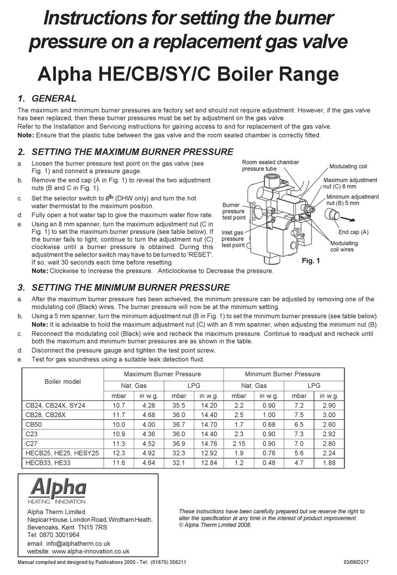
5.5 CHECK THE BURNER PRESSURES - Fig. 17
Turn the boiler off. Loosen the burner pressure test point screw on the gas valve and connect a pressure gauge. Allow the
boiler to run for 10 minutes and check the burner pressures.
Hot water mode
1. Set the selector switch to (DHW only) and fully open a hot water tap.
2. The burner will light at the ignition rate and the burner pressure
will increase to maximum.
3. Gradually close the hot tap and check that the burner pressure
decreases to its minimum. Fully open the tap and check that the
burner pressure increases. Close the tap and check that the
burner goes off.
The burner pressure settings have been factory set and do not
require adjusting. If incorrect, check that the inlet gas pressure is
20 mbar. If the inlet gas pressure is not 20 mbar, either the
pipework is too small or the gas supply to the house is
insufficient, in which case contact your gas supplier.
Central heating mode
1. Set the selector switch to (DHW and CH).
2. The burner will light at the ignition rate and will increase to the
factory pre-set maximum output.
3. Turn off the boiler. Disconnect the pressure gauge and tighten the test point screw.
Test for gas soundness using suitable leak detection fluid.
Note: Refer to Technical Data, section 2.1 for burner pressure settings.
5.6 FINAL COMMISSIONING
1. Allow the heating system to heat up, then balance the system to achieve the necessary temperature difference across the heating
flow and return pipes at the boiler and check the system volume and pressure. (Refer to Technical Data, sections 2.8 and 2.10).
2. Turn off the boiler.
3. Thoroughly flush out the water pipework and clean the filters in the heating return and mains water inlet isolating valves.
4. Re-pressurise the system as described in section 5.1.
5.7 FINAL ASSEMBLY
1. Raise the control panel and secure in position with the screws previously removed.
Note: Ensure the gas control locates correctly over the black cap on the gas valve knob.
2. Place the front casing in position over the boiler ensuring the bottom is located behind the control panel and secure in
position at the top using the screws previously removed.
3. If the boiler is to be left in service with the User, set the controls, clock (if fitted, see User's Operating manual) and room
thermostat (if fitted) to the User's requirements.
4. If the boiler is not to be handed over immediately, close the boiler gas service cock and switch off the electrical supply.
5. If there is any possibility of the boiler being left during frost conditions, then the boiler and system should be drained.
(Refer to Component Replacement, section 8.2).
It is recommended that a label is attached to the boiler drawing attention to the fact that the system has been drained.
6. Complete the details of the installation on the back page of this manual.
Alpha 240X - Commissioning
Burner pressure
test point
Inlet gas pressure
test point
Fig. 17