Altair DA-410 User manual

DA-410
DISTRIBUTION AMPLIFIER/ZONE MIXER/MIC SPLITTER
OWNERS MANUAL
EQUIPOS EUROPEOS ELECTRÓNICOS, S.A.L
Avda. de la Industria, 50. 28760 TRES CANTOS-MADRID (SPAIN).
34-1-804 32 65 34-1-804 43 58 altair@altairaudio.com
www.altairaudio.com

2
DISTRIBUTION AMPLIFIER/ZONE MIXER/MIC SPLITTER DA-410.
1. INTRODUCTION................................................................................................................................................................................. 3
2. SWITCHES, CONTROLS,ADJUSTMENTS AND CONNECTORS................................................................................................... 4
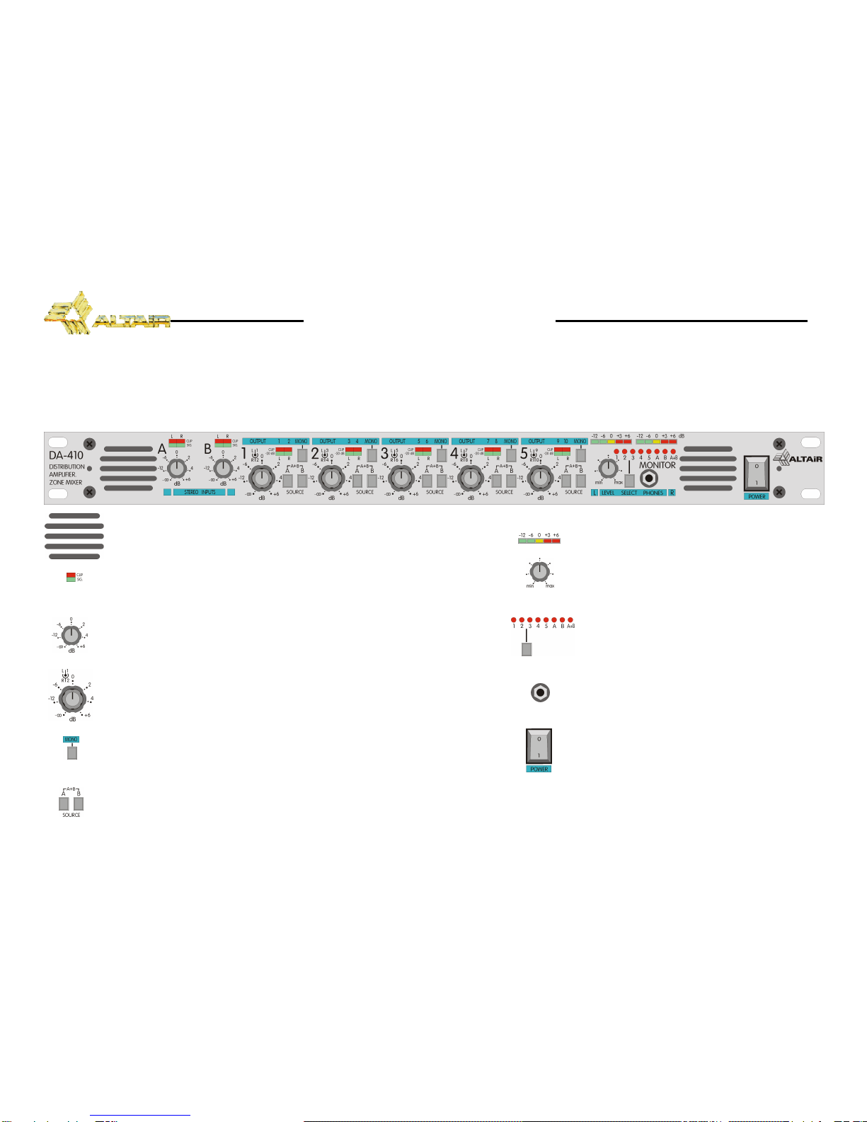
FRONT PANEL.................................................................................................................................................................................. 4
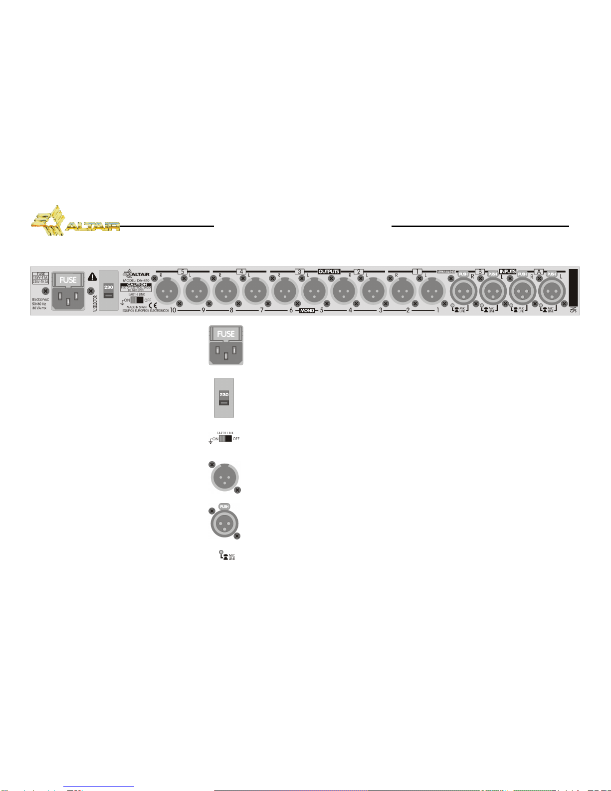
REAR PANEL..................................................................................................................................................................................... 5
3. WORKING PRECAUTIONS............................................................................................................................................................... 6
4. INSTALLATION .................................................................................................................................................................................. 6
UNPACKING.................................................................................................................................................................................... 6
MOUNTING...................................................................................................................................................................................... 6
CHANGING THE VOLTAGE............................................................................................................................................................ 6
CHANGING THE FUSE.....................................................................................................................................................................7
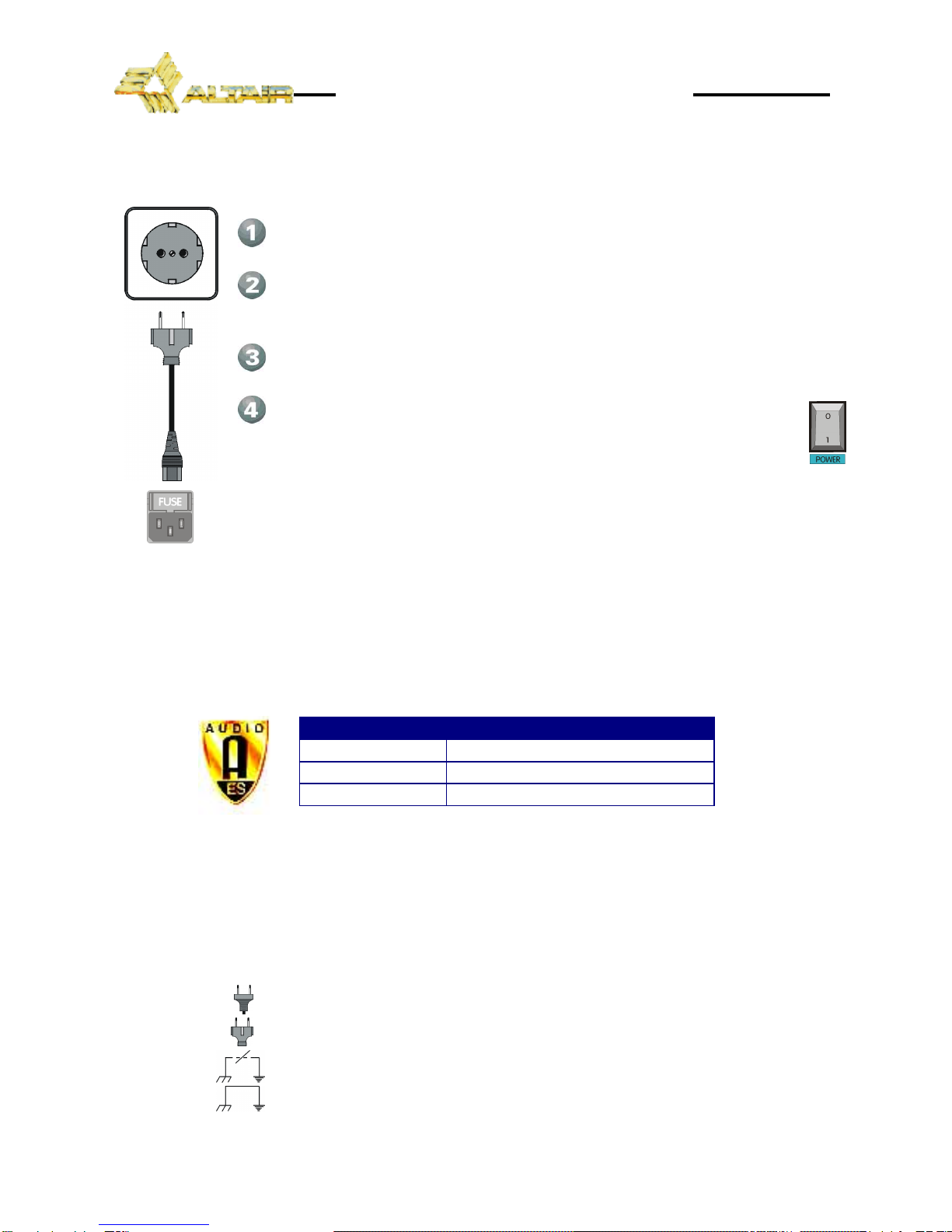
CONNECTING TO THE MAINS....................................................................................................................................................... 8
INPUT CONNECTION...................................................................................................................................................................... 8
UNBALANCED INPUT: ................................................................................................................................................................ 9
BALANCED INPUT:.....................................................................................................................................................................10
OUTPUT CONNECTION.................................................................................................................................................................10
UNBALANCED OUTPUT:.............................................................................................................................................................11
BALANCED OUTPUT:.................................................................................................................................................................12
GROUND LINK................................................................................................................................................................................12
5. OPERATION......................................................................................................................................................................................13
TURN ON DELAY CIRCUIT.............................................................................................................................................................13
SIGNAL AND OVERLOAD INPUT INDICATOR.............................................................................................................................13
INPUT LEVEL CONTROL.................................................................................................................................................................13
SIGNAL AND OVERLOAD OUTPUT INDICATOR.........................................................................................................................13
OUTPUT LEVEL CONTROL.............................................................................................................................................................14
MONO SIGNAL SWITCH...............................................................................................................................................................14
INPUT SIGNAL SELECTOR.............................................................................................................................................................14
MONITOR SIGNAL SELECTOR.......................................................................................................................................................14
MONITOR SIGNAL VU-METER......................................................................................................................................................15
MONITOR LEVEL CONTROL ..........................................................................................................................................................15
HEADPHONES OUTPUT................................................................................................................................................................15
MINIATURE SPEAKERS ..................................................................................................................................................................15
MIC/LINE INPUT SIGNAL SELECTOR............................................................................................................................................15
OPERATING LEVEL CHART............................................................................................................................................................16
6. OPTIONS...........................................................................................................................................................................................16
INPUT TRANSFORMER (IT-DA)......................................................................................................................................................16
OUTPUT TRANSFORMER (OT-DA) ...............................................................................................................................................16
EQUALISER CARD (TE-67) .............................................................................................................................................................16
SECURITY COVER (TP-1).................................................................................................................................................................17
KEY LOCKED SECURITY COVER (TS-1) .........................................................................................................................................17
7. SPECIAL OPERATIONS ....................................................................................................................................................................17
INPUT TRANSFORMER (IT-DA)......................................................................................................................................................19
OUTPUT TRANSFORMER (OT-DA) ...............................................................................................................................................19
EQUALISER CARD..........................................................................................................................................................................20
EQUALIZER CARD CONFIGURATION........................................................................................................................................21
GAIN CALCULATION............................................................................................................................................................21
FILTER FREQUENCY CALCULATION.....................................................................................................................................22
BANDWIDTH CALCULATION (Q).........................................................................................................................................23
GAIN VARIATION ................................................................................................................................................................24
NON STANDARD CONFIGURATION EXAMPLES................................................................................................................25
PLACING AN EQUALIZER CARD.........................................................................................................................................25
LIFTING THE XLR INPUT GROUNDS ...........................................................................................................................................26
8. BLOCK DIAGRAM AND HOW IT WORKS ...................................................................................................................................26
9. REPAIR GUIDE.................................................................................................................................................................................28
10. APPLICATION EXAMPLES............................................................................................................................................................29
DISTRIBUTION AMPLIFIER APPLICATION EXAMPLE.................................................................................................................29
ZONE MIXER APPLICATION EXAMPLE.......................................................................................................................................30
MIC SPLITTER APPLICATION EXAMPLE.......................................................................................................................................31
11. TECHNICAL SPECIFICATIONS.......................................................................................................................................................32
12. WARRANTY....................................................................................................................................................................................33

3
DISTRIBUTION AMPLIFIER/ZONE MIXER/MIC SPLITTER DA-410.
1. INTRODUCTION
Congratulationson your purchase of the ALTAIR distribution amplifier/zone mixer/mic splitter
DA-410. Our dilated experience in the design and manufacture of effect processing equipment, had
led to us to carry out this distribution amplifier/zone mixer/mic splitter of great performances.
There is a lot the characteristics that make of the ALTAIR DA-410, one of themost highlighted of
the audio professional market, here enumerated some:
The ALTAIR DA-410 is a high performance distribution amplifier/zone mixer/mic splitter, compact,
only one rack 19" unit high, and is able to process two stereo input signals to obtain five stereo output
signals, both with independent level control.
Used as mixer (Zone Mixer), the unit could control five zones in stereo mode or ten in monomode
(or any other combination) from the mix of its two stereo input signals.
As a audio distributor, allow obtaining up to ten mono output signals, or five in stereo mode for its
use in press rooms, recording units, audio production, broadcast, etc. Since it has two stereo inputs,
allow using the stereo input B as emergency input signal (reserve).
Individually selected MIC/LINE input preamplifiers allows microphone or line signals splitting to
additional mixers without quality and headroom degradation. Up to 4x8 or 1x10 active splitting is
possible.
One MONO switch by Zone allows to convert the output signals in order to adapt them to
monophonic equipment. If the input signals are monophonic, this switch isequally useful in order to
duplicate them to L, R (stereo).
The unit has a monitoring system or PFL with incorporate speakers, headphone output and
selectable Vu-meter allows analysing and calibrating the input signals and all the outputs. This stereo
monitoring system allows a simple and efficient control of audio continuity in moderate noisy
environments.
All the inputs and outputs are electronically balanced (XLR) and admit as option, input and output
transformers in order to improve the common moderejection ratioor provide galvanicisolation.
Up to two parametric equaliser cards TE-F could be installed as option, in each one of the ten
outputs, permitting the appropriate tonal correction to each zone or speaker system.
Naturally, you want to use your distribution amplifier/zone mixer/mic splitter, but before
beginning is important that you read this manual. This manual will help you to install and use your new
distribution amplifier/zone mixer/mic splitter. It is very important that you read it carefully, mainly the
paragraphs marked as NOTE, PRECAUTION and DANGER, for your security.
Save the original packing, you can re-use it to transport the unit. NEVER SHIP THE DISTRIBUTION
AMPLIFIER/ZONE MIXER/MIC SPLITTER WITHOUT IT'S ORIGINAL PACKING.

4
DISTRIBUTION AMPLIFIER/ZONE MIXER/MIC SPLITTER DA-410.
2. SWITCHES, CONTROLS, ADJUSTMENTS AND CONNECTORS
These are the switches, controls, adjustments and connectors that you could find in your ALTAIR distribution amplifier/zone mixer/mic splitter. The
description and explanation of each one of them, you will find in the corresponding section.
FRONT PANEL
MINIATURE SPEAKERS. MONITOR SIGNAL VU-METER.
SIGNAL AND OVERLOAD INDICATOR. MONITOR LEVEL CONTROL.
INPUT LEVEL CONTROL. MONITOR SIGNAL SELECTOR.
OUTPUT LEVEL CONTROL (CONCENTRIC). HEADPHONES OUTPUT.
MONO SIGNAL SWITCH. POWER SWITCH.
INPUT SIGNAL SELECTOR.

5
DISTRIBUTION AMPLIFIER/ZONE MIXER/MIC SPLITTER DA-410.
REAR PANEL
MAINS CONNECTOR AND FUSE HOLDER.
VOLTAGE SELECTOR.
EARTH LINK SWITCH.
OUTPUT SIGNAL CONNECTOR XLR-3-32.
INPUT SIGNAL CONNECTOR XLR-3-31.
MIC/LINE INPUT SIGNAL SELECTOR.

6
DISTRIBUTION AMPLIFIER/ZONE MIXER/MIC SPLITTER DA-410.
3. WORKING PRECAUTIONS
The manufacturer is not responsible of any damage occurred in the distribution amplifier/zone
mixer/mic splitter unit outside the limits of the warranty or those produced by not keeping in mind the
working precautions.
Mains voltage must be correct and the same as that setting on therear of the unit voltage
switch. Damage caused byconnection to improper AC voltage is not covered by any
warranty.
DANGER: Inside the distribution amplifier unit there are high voltages, doesn't open it.
The unit doesn't contain elements that could be repaired by the user. Whenever the
distribution amplifier unit is connected to the mains, contains elements with high voltages.
In order to disconnect the unit completely, you must disconnect it of the mains.
CAUTION: Protect the distribution amplifier from the rain and moisture. Ensure that no
objects or liquids enter it. If liquid is spilled into the unit, disconnect it from the mains and
consult a qualified service technician.
Don't place the unit close to heat sources.
4. INSTALLATION
UNPACKING
Before leaving from factory, each distribution amplifier was carefully inspected and tested.
Unpack and inspect the unit for any damage that may have occurred during shipment. If any
damage is found, doesn't connect the unit to the mains, notify the salesperson immediately,
because a qualified service technician must inspect the unit.
Save the original packing, you could use if you need to transport the unit. NEVER SHIP THE
DISTRIBUTION AMPLIFIER/ZONE MIXER/MIC SPLITTER WITHOUT IT'S ORIGINAL PACKING.
MOUNTING
It is always advisable to mount the unit inrack, either for mobile or fixed installations, for
protection, safety, aesthetics, etc.
The ALTAIR DA-410 is designed for standard 19" rack mounting, and occupy 1u high rack
space.
CHANGING THE VOLTAGE
The distribution amplifier/zone mixer/mic splitter unit is set to operate at 230V, 50-60Hz and
at 115V, 50-60Hz.
Make sure that theunit is disconnected of the mains.
Set up the voltage selector, placed at the unit rear panel, in the position that shows the
voltage, which you want to connect it.

7
DISTRIBUTION AMPLIFIER/ZONE MIXER/MIC SPLITTER DA-410.
Distribution amplifier/zone mixer/mic splitter set up to 230 V.
Distribution amplifier/zone mixer/mic splitter set up to 115 V.
Make sure that the fuse is the right one for the selected voltage:
FUSE (230V. 50-60 Hz) FUSE (115V. 50-60 Hz)
T0,5A. T1A.
CHANGING THE FUSE
The distribution amplifier/zone mixer/mic splitter unit is set to operate at 230V, 50-60Hz or at
115V, 50-60Hz.
Make sure that theunit is disconnected from the mains.
In the unit rear panel, is placed the mains connector and the fuse holder. The box bellow this
mains connector is called fuse holder. Take out the fuse holder.
Upon extracting the fuse holder, the fuse will appear, take out it and change for the new one.
Insert the fuse holder into the mains connector again.
NOTE: The fuseholder provide a place for spare fuse.
CAUTION: Always make sure upon changing the fuse, that this is the adequate for the selected
mains voltage (T1A for 115V and T0,5A for 230V).

8
DISTRIBUTION AMPLIFIER/ZONE MIXER/MIC SPLITTER DA-410.
CONNECTING TO THE MAINS
The connection of the distribution amplifier/zone mixer/mic splitter power supply to the
mains takes place by a standard cord included in the box.
Make sure that the unit power switch is at 0 position (turned off).
Insert the female I.E.C. connector of the tripolar cable into the unit power supply
male connector,placed at the rear panel.
Insert the male connector of the tripolar cable into the mains plug.
Turn on the unit power switch. In that moment the MONITOR SIGNAL
SELECTOR LED indicator will light, indicating that the unit is turned on.
CAUTION: Make sure that the mains voltage is the correct as well as their fuse is the
adequate.
INPUT CONNECTION
The distribution amplifier input signals is carried out through four XLR-3-31 female
connectors, two per stereo channel. The input connections are balanced, with a nominal
impedance of 5 kΩ(2,5kΩunbalanced) with the input set-up in line mode and 2 kΩ(1kΩ
unbalanced) with the input set-up in mic mode. The next list shows the input pins correspondence
as A.E.S recommendation practice:
INPUT CONNECTOR XLR-3-31
PIN 1 GND
PIN2 HOT (+)
PIN3 COLD (-)
The input connection dependson two factors, the first is the type of input signal balanced or
unbalanced, and the second the ground configuration of the sound source (floating or ground-
referenced). The next pictures shows some of the different possibilities of connection, relying on the
type of input signal, balanced or unbalanced and according to the ground configuration of the
equipment (floating or ground-referenced).
NOTE: All the inputs and outputs of the unit accepts phantom power.
In the next diagrams, we use the following symbols:
Sound source withmains cord without ground connection.
Sound source withmains cord with ground connection.
Sound source with the EARTH-LINK OFF.
Sound source with the EARTH LINK ON.

9
DISTRIBUTION AMPLIFIER/ZONE MIXER/MIC SPLITTER DA-410.
UNBALANCED INPUT:
This type of connection will be used when the sound source doesn't provide balanced
output. When possible, employ the connection type 1.
1) Using twin-lead shielded cable:
2) Using single conductor shielded cable:

10
DISTRIBUTION AMPLIFIER/ZONE MIXER/MIC SPLITTER DA-410.
BALANCED INPUT:
OUTPUT CONNECTION
The distribution amplifier/zone mixer/mic splitter output signal is carried out through ten XLR-
3-32 male connectors, two per stereo channel. Theoutputs are balanced, with anominal
impedance of 100 Ω. The next list shows the input pins correspondence as A.E.S recommendation
practice:
OUTPUT CONNECTOR XLR-3-32
PIN 1 GND
PIN2 HOT (+)
PIN3 COLD (-)
The output connection depends on two factors, the first is the type of input signal balanced or
unbalanced, and the second the ground configuration of the sound destinationunit (floating or
ground-referenced). The next pictures shows some of the different possibilities of connection,
relying on the type of output signal, balanced or unbalancedand according to the ground
configurationof the equipment (floating or ground-referenced).
NOTE: All the outputs and inputs of the unit accepts phantom power.
In the next diagrams, we use the following symbols:
Sound destinationunit with mains cord without ground connection.
Sound destinationunit with mains cord with ground connection.
Sound destinationunit with the EARTH-LINK OFF.
Sound destinationunit with the EARTH LINK ON.

11
DISTRIBUTION AMPLIFIER/ZONE MIXER/MIC SPLITTER DA-410.
UNBALANCED OUTPUT:
This type of connection will be used when the sound destination unit doesn't provide a
balanced input. When possible, employ the connection type 1.
1) Using twin-lead shielded cable:
2) Using single conductor shielded cable:

12
DISTRIBUTION AMPLIFIER/ZONE MIXER/MIC SPLITTER DA-410.
BALANCED OUTPUT:
GROUND LINK
In some installations, it might be necessary to isolate the distribution amplifier/zone
mixer/mic splitter electric ground, from the system mains earth, in order to avoid ground loops that
could generateunwanted noises. For this reason, the unit provides an EARTH-LINK switch placed
at the rear panel in order to lift the mains earth from the unit.
MAINS EARTH LINKED WITH THE DISTRIBUION AMPLIFIER/
ZONE MIXER/MIC SPLITTER ELECTRIC GROUND.
MAINS EARTH LIFTED FROM THE DISTRIBUION AMPLIFIER/
ZONE MIXER/MIC SPLITTER ELECTRIC GROUND.
NOTE: For securityreasons, the earth connection to the mains is linked with the unit chassisin both
cases.
CAUTION: Always operate the unit with the AC ground wire connected to the
electrical system ground. Precautions shouldbe taken so that the means of
grounding of a piece of equipment is not defeated. For this circumstance, NEVER lift
the mains earth AC ground to avoid possible accidents. For your security, NEVER use
ground isolator adapters; instead it is recommended the EARTH -LINK switch.

13
DISTRIBUTION AMPLIFIER/ZONE MIXER/MIC SPLITTER DA-410.
5. OPERATION
The utility of the distribution amplifier/zone mixer/mic splitter is to process two input stereo
signals entering the unit to obtain five output stereo signals, both with independent level control.
Used as mixer (Zone Mixer), the unit could control five zones in stereo mode or ten in mono
mode (or any other combination) from the mix of its two stereo input signals.
As a audio distributor, allowobtainingup to ten monooutput signals, or five in stereo mode for
its use in press rooms, recording units, audio production, broadcast, etc. Since it has two stereo
inputs, allow using the stereo input B as emergency input signal (reserve).
Individually selected MIC/LINE input preamplifiers allows microphone or line signals splitting to
additional mixers without quality and headroom degradation. Up to 4x8 or 1x10 active splitting is
possible.
NOTE: For simplicity in the next explanations, we are considering the unit as operating with stereo
inputs and outputs signals. Mono operation is similar. Exceptions are detailed separately when
necessary.
TURN ON DELAY CIRCUIT
The ALTAIR DA-410 incorporates a delay circuit, consisting of a relay, which protects the
output signal from switch-on transients. This delay takes two seconds, and in the meantime the
unit remains in mute.
SIGNAL AND OVERLOAD INPUT INDICATOR
The distribution amplifier/zone mixer/mic splitter incorporates a multipurpose signal
and overload circuiton each input. The indicator is made up of two LED's (one red and
one green) placed at the unit front panel.
This two point level circuit indicates the highest level reached inside the unit input circuits and
warns the operator about possible problems. When the level indicator lights green, the internal
level has reached -20dBv. (signal present led). Shouldany internal level is near overload (+15 dBv)
the level indicator lights on red to warn the security limit has been surpassed. On that case the unit
has a 6 dB extra dynamic reserve or headroom. Inorder to correct this problem should lower the
level of that input or decreases the input signal (the output signal of the previous unit).
INPUT LEVEL CONTROL
Each stereo input (A & B) provides a gauged input level control between - ∞and
+6 dB placed at the front panel. This input level control affect to the stereo signal level,
therefore this affect to the L &R inputs at the same time.
SIGNAL AND OVERLOAD OUTPUT INDICATOR
The unit incorporates a multipurpose signal and overload circuit on each output.
The indicator is made up of two LED's (one red and one green) placed at the unit front
panel.

14
DISTRIBUTION AMPLIFIER/ZONE MIXER/MIC SPLITTER DA-410.
This multipoint level circuit indicates the highest level reached inside the unit output circuits
and warns the operator about possible problems. When the level indicator lights green, the
internal level has reached -20 dBv. (signal present led). Should any internal level is near overload
(+15 dBv) the level indicator lights on red to warn the security limit has been surpassed. On that
case the unit has a 6 dB extra dynamic reserve or headroom. In order to correct this problem
should lower the level of thatoutput or decreases the input signal.
OUTPUT LEVEL CONTROL
Each unit stereo output (1, 2, 3, 4 & 5) provides a gauged input level control
between - ∞and +6 dB placed at the front panel. This output level control is rotary
and concentric. Internal knob is dedicated to control the Left (L) output level and the
external knob for Right (R) output level. When operating in monomode, this
corresponds to outputs1, 3, 5, 7, 9 and 2,4, 6, 8 and 10respectively.
MONO SIGNAL SWITCH
Each of the five sections incorporates a MONO switch that mix L and R incoming
signals routing it to the relevant outputs at the selected front panel output levels. When
this switch is not depressed, the L and R outputs are independent (stereo).
This switch allows adapting the stereo signals to monophonic equipment, and
equally duplicate the monophonic input signals for stereo equipments.
NOTE: If the input signal is monophonic, it's say, the input signal only are connected to L or R, upon
pressing the MONO switch, it will produce an attenuation of 6 dB in each one of the outputs. In
order to avoid this signal loss, it is advisable duplicate the inputs with an external bifurcation or
compensate it with the output gain controls.
INPUT SIGNAL SELECTOR
The input signal selector placed at the front panel, allow us select the input signal
that we will obtain at the output. When the A switch is depressed, we will obtain in the
stereo output (1, 2, 3, 4, or 5) the A stereo input signal. If we depressed the B switch, we
will obtain the B stereo input signal in the stereo output, and if we pressed the two at
the same time, we will obtain the sum of the two stereo input signals in L and R outputs
(the two outputs will have the same signal determined by the input level controls).
MONITOR SIGNAL SELECTOR
The monitor signal selector, placed at the front panel, allow us to
choose fromany input or output stereo signals formonitoring purposes.
Selection is made sequentially by a momentary push button. This selector
allow us to monitor (either by means of the miniature speakers, or the
headphone output), all the outputs and inputs (A and B) and the sum of the
two stereo inputs (A+B). Upon turn on the unit, the monitor signal selector is placed automatically
in the output 1 position.

15
DISTRIBUTION AMPLIFIER/ZONE MIXER/MIC SPLITTER DA-410.
MONITOR SIGNAL VU-METER
The selected monitor signals drives a Stereo calibrated VU-METER ranging
from -12 dB, -6 dB, 0 dB, +3 dB and +6 dB. (0dB ref. 0 dBu). This 6 led VU-METER is
connected pre-monitor level and is intended for precise signal calibration. Refer to previous
paragraph about MONITOR SIGNAL SELECTOR.
MONITOR LEVEL CONTROL
The selected monitor stereo signal incorporates a stereo level control placed
at the front panel in order to control the headphones output level, or the miniature
speakers volume.
NOTE: In order to avoid breaks, never leave disregarded themonitor output level control. Avoid
prolonged saturation.
HEADPHONES OUTPUT
The headphonesoutput are carried out by means of a stereo jack placed at the
front panel. This output can managehigh impedance (100Ω-600 Ω) standard stereo
headphones.
The signal that appears in the headphones output is the chosen in the monitor
signal selector and the level could be regulated with the monitor level control.
Upon introducing a stereo jack in theheadphones output, automatically the miniature
speakers are disconnected.
MINIATURE SPEAKERS
The monitor listening of the selected signal, drives a pair of stereo
miniature speakers placedat the front panel. The volume control of these
miniature speakers is carried out by means of themonitor level control. Upon
introducing a stereo jack in the headphonesoutput, automatically the miniature
speakers are disconnected.
This stereo monitoring system allows a simple and efficient control of audio continuity in
moderate noisy environments.
NOTE: In order to avoid breaks, never leave disregarded themonitor output level control. Avoiding
extend saturations.Avoid prolonged saturation.
MIC/LINE INPUT SIGNAL SELECTOR
The MIC/LINE input signal selector, placed at the rear panel, allows choosing
between line input signals or microphone input signals. The distribution amplifier/zone
mixer/mic splitter incorporates one mic/line input selector switch per input. Normal
position corresponds to line mode, and depressed to microphone signals inputs.
Nominal gain is 0 dB when line mode and +12 dB when configured as Mic.
Due to the reduced gain (+12 dB) in MIC mode, the DA-410 output signals must be externally
connected to preamplifiers ormixers into its MIC inputs.

16
DISTRIBUTION AMPLIFIER/ZONE MIXER/MIC SPLITTER DA-410.
The MIC mode is not intended as amicrophone preamplifier. Instead, it accommodates or
adapts microphone impedances to theunit allowing perfect match between microphones and
long run cabling to external mixers.
This reduced gain, is optimised to use the unit as audio SPLITTER: If the input and output level
control is 0 dB or below, you can connect to the input either dynamic microphones, condenser
microphones or direct injectionboxes without thenecessity of setting-up theunit for each signal,
getting an autonomous operation.
This switch permits an extra gain of 12 dB for some applications. It is important to remember
that the input impedance becomes lower (2 kΩ)and upon connecting to old600 Ωsystems, an
insert loss of 2.3 dB will take place.
NOTE: All the inputs of the unit accept phantom power.
OPERATING LEVEL CHART
MODE INPUT LEVEL
ADJUSTMENT OUTPUT LEVEL
ADJUSTMENT MAXIMUM INPUT
LEVEL TOTAL GAIN
0 dB + 9 dBu +12 dB
0 dB +6 dB + 3 dBu +18 dB
0 dB + 3 dBu +18 dB
MIC +6 dB +6 dB -3 dBu +24 dB
0 dB + 22 dBu 0 dB
0 dB +6 dB + 16 dBu +6 dB
0 dB + 16 dBu +6 dB
LINE +6 dB +6 dB + 10 dBu +12 dB
6. OPTIONS
In this section will explain the different available options for the distribution amplifier/zone
mixer/mic splitter.
INPUT TRANSFORMER (IT-DA)
In order to improve the common mode rejection ratio and get a galvanic isolation with the
previous part of the audio system, it is available an input transformer.
Each XLR-3-31 input has an insert point for the input transformer; therefore, you could mount
four input transformers in the unit.
The provided transformers fulfil the isolation rule of 1.5 kV.
OUTPUT TRANSFORMER (OT-DA)
In order to get a galvanic isolation with the next part of the audio system, it is available an
output transformer.
Each XLR-3-32 output has an insert point for the output transformer; therefore, you could
mount tenoutput transformers in theunit.
The provided transformers fulfil the isolation rule of 2 kV.
EQUALISER CARD (TE-67)
In certain installations it is advisable the use of equalisation points in order to improve the
system frequency response. Inserting an equalisation directly in the distribution amplifier/zone

17
DISTRIBUTION AMPLIFIER/ZONE MIXER/MIC SPLITTER DA-410.
mixer/mic splitter is cheaper than utilise a graphic equaliser, and also avoids unwanted
manipulations.
The optional equaliser card provides a full parametric equalisation point. It means, you can
arbitrary choose and set-up the equalisation points parameters: gain, bandwidth and centre
frequency.
Two equalisation points per output (XLR-3-32) are available.
SECURITY COVER (TP-1)
In some installation, it could be necessary to tamper proof the front panel controls avoiding
unwanted or accidental manipulations. For this purpose, it is available as an option, a transparent
plastic security cover. The installation is very easy, by means of two screws provided.
KEY LOCKED SECURITY COVER (TS-1)
In some installations it is necessary isolate the distribution amplifier/zone mixer/mic splitter
controls more securely than with the plastic security cover. For this extra protection, it is available
an all-metallic and lockable security cover. This option cover fits into the four rack holes of the unit
and includes rearnut-bars allowing the installation as a stand-alone unit.
This cover prevents also from unauthorised extraction of the unit when rack mounted.
7. SPECIAL OPERATIONS
In order to set-up some of the distribution amplifier possibilities, the unit must be opened. Care
must be taken when removing the bottom cover as the line transformer is attached to it.
NOTE: This type of operations takes place with the unit open, for what it should be carried out by a
qualified technician.
DANGER: Before opening the unit, disconnect it from the mains. It is important to indicate that
although theunit is powerout (with the power switch in 0 position), if it continues connected to the
mains there are different parts of the unit that are subjected to high voltage.
CAUTION: Protect the distribution amplifier from the rain and moisture, mainly if it is open. If liquid is
spilled into the unit, disconnect it from the mains and consult a qualified service technician.
The next picture shows the main PCB components layout of the unit to be used in the following
sections. Symmetry of the four input and ten output blocks makes ease the set-up, inspection, post-
servicing or installation of the available options.
Components naming starts in the upper left corner running to the opposite corner.

18
DISTRIBUTION AMPLIFIER/ZONE MIXER/MIC SPLITTER DA-410.

19
DISTRIBUTION AMPLIFIER/ZONE MIXER/MIC SPLITTER DA-410.
INPUT TRANSFORMER (IT-DA)
In order to improve the input common mode rejection ratio and for a galvanic isolation with
the previous part of the audio system, it is available an input transformer.
Each XLR-3-31 input has an insert point for the input transformer; therefore, you could mount
four input transformers in the unit. In the following table are shown the correspondence between
the inputs and their corresponding input transformers.
INPUT TRANSFORMER POSITION LINKS TO REMOVE
INPUT AL TR1 LK1 y LK2
INPUT AR TR2 LK3 y LK4
INPUT BL TR3 LK5 y LK6
INPUT BR TR4 LK7 y LK8
Before placing the transformer, you should remove the links corresponding to the input
transformer indicated in the following chart:
In the following picture is shown the placement of the input transformer TR1 corresponding to
the IN AL input. It is important to keep in mind the placement of the input transformer pins so that
they coincide with the main board (four to the left and three to the right).
Remove the links corresponding to the input transformer. In
this case LK1 and LK2.
Place the input transformer, keeping in mind the position of
their pins (four to the left and three to the right), and solder it to the
main board.
OUTPUT TRANSFORMER (OT-DA)
In order to make a galvanic isolation with the next part of the audio system, it is available an
output transformer.
Each XLR-3-32 output has an insert point for the output transformer; therefore, you could
mount tenoutput transformers in theunit. In the following table are shown the correspondence
between the outputs and their corresponding outputs transformers and the links that you must
remove to place the output transformer.

20
DISTRIBUTION AMPLIFIER/ZONE MIXER/MIC SPLITTER DA-410.
OUTPUT TRANSFORMER POSITION LINKS TO REMOVE
OUT 1L (1) TR5 LK9 and LK10
OUT 1R (2) TR6 LK11 and LK12
OUT 2L (3) TR7 LK13 and LK14
OUT 2R (4) TR8 LK15 and LK16
OUT 3L (5) TR9 LK17 and LK18
OUT 3R (6) TR10 LK19 and LK20
OUT 4L (7) TR11 LK21 and LK22
OUT 4R (8) TR12 LK23 and LK24
OUT 5L (9) TR13 LK25 and LK26
OUT 5R (10) TR14 LK27 and LK28
In the following picture is showing the placement of the output transformer TR5
corresponding to the OUT 1L (1) output. It is important to keep in mind the placement of the output
transformer pins so that they coincide with the main board (seven to the top and six to the bottom).
Remove the links corresponding to the output transformer. In this
case LK9 and LK10.
Place the output transformer, keeping in mind the
position of their pins (seven to the top and six to the
bottom), and solder it to the main board.
EQUALISER CARD
Two equaliser cards connectors are provided per output. Next table explains
the correspondence between the affected output and the labelled insert connector
as appears in the main distribution amplifier PCB.
EQUALISER CARD INSERT CONNECTORS
OUT 1L
(1) OUT 1R
(2) OUT 2L
(3) OUT 2R
(4) OUT 3L
(5) OUT 3R
(6) OUT 4L
(7) OUT 4R
(8) OUT 5L
(9) OUT 5R
(10)
J1, J2 J3, J4 J7, J8 J10, J11 J12, J13 J15, J16 J17, J18 J21, J22 J23, J24 J26, J27
When the eq card is not installed, the signal path must be closed with a jumper.
Keep in mind this circumstance whenever you change, update or place for the first time an
equaliser card. Of course, in order to insert the equaliser card, you should remove the connector
jumper in which you want to place the equaliser card.
Table of contents
Other Altair Amplifier manuals
Popular Amplifier manuals by other brands

Schoeps
Schoeps VMS 5 U user manual

Jensen
Jensen XA4150 How to install and operate

Kenwood
Kenwood XXV-02A - 25th Anniversary Products... instruction manual

Acurus
Acurus ACT-3 owner's manual

Audio Analogue
Audio Analogue MAESTRO DUECENTO owner's manual

Kaption Audio
Kaption Audio A150.2 Owner's manual & installation guide