3. WORKING PRECAUTIONS
The manufacturer is not responsible of any damage occurred in the graphic equaliser
unit outside the limits of the warranty or those produced by not keeping in mind the working
precautions.
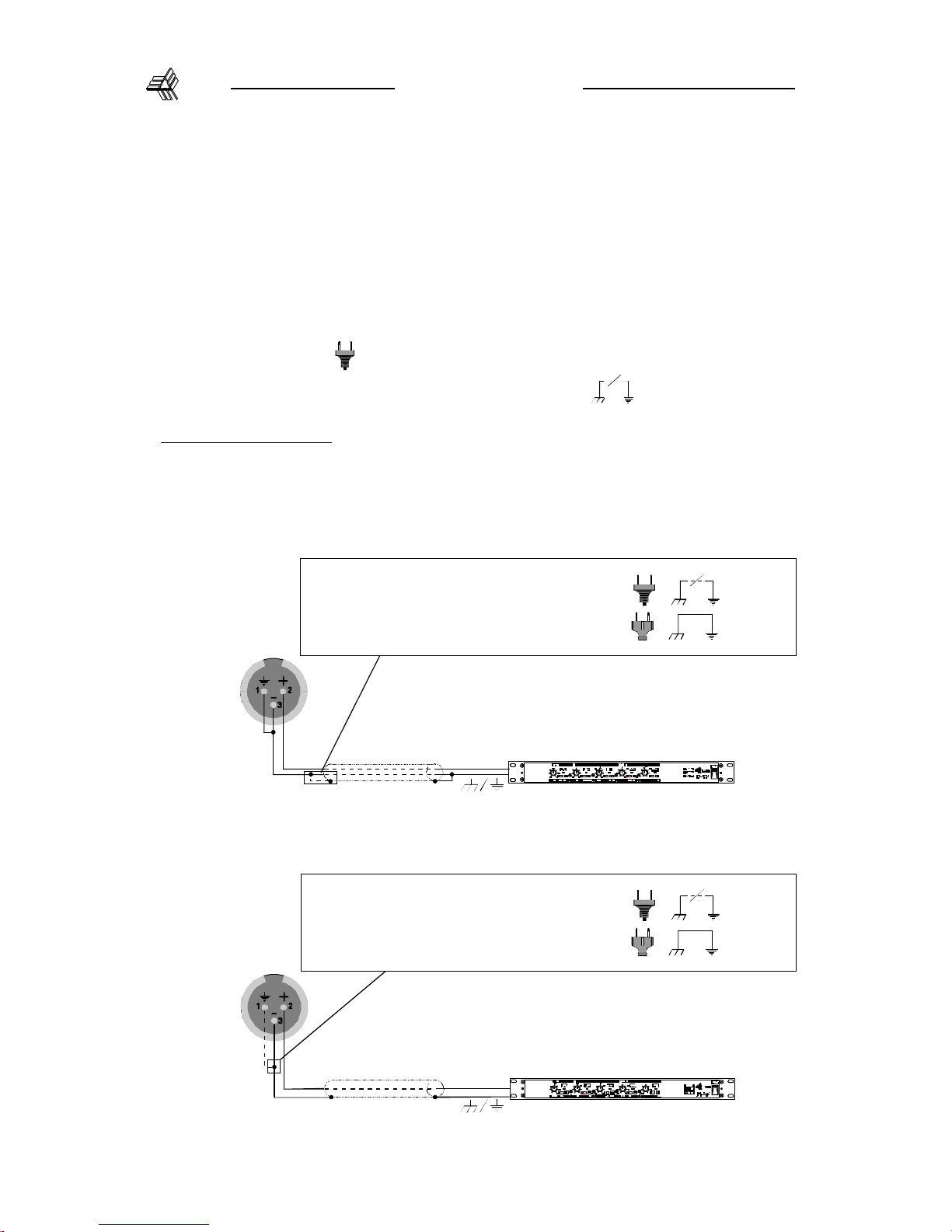
Always operate the unit with the AC ground wire connected to the electrical
system ground. Precautions should be taken so that the means of grounding of a
piece of equipment is not defeated.
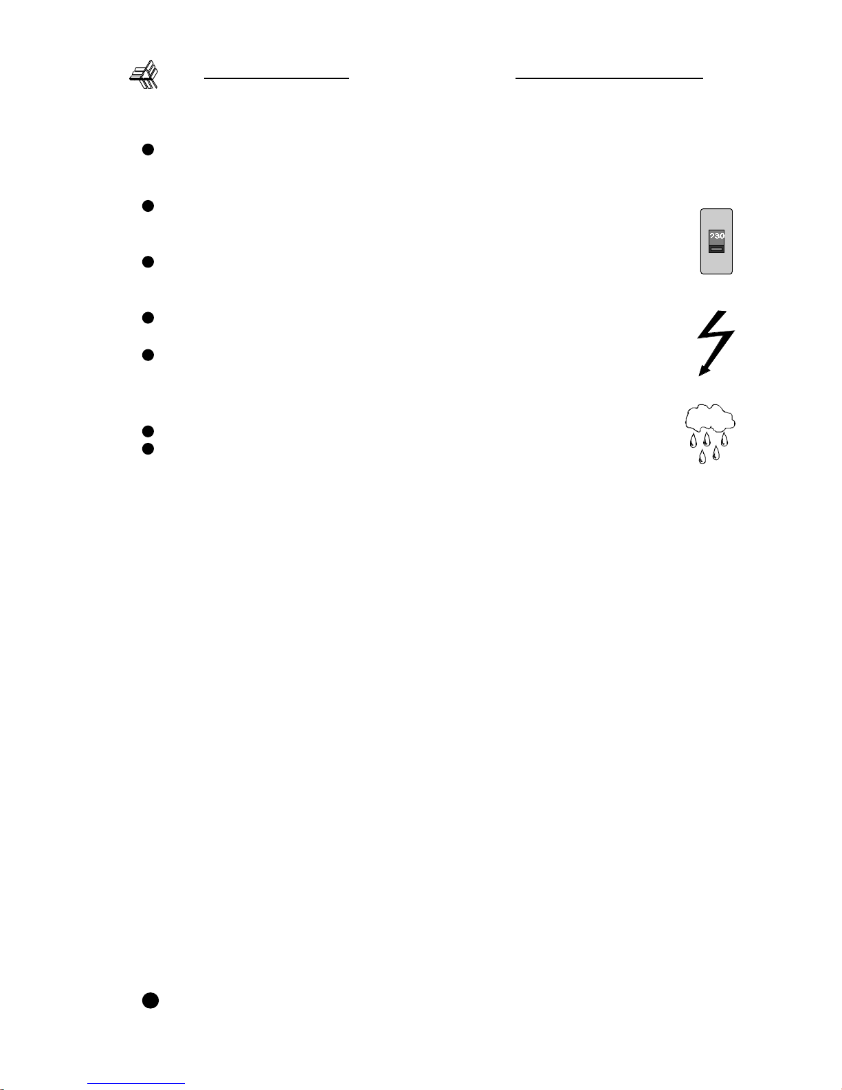
Mains voltage must be correct and the same as that setting on the rear of the unit
voltage switch. Damage caused by connection to improper AC voltage is not cov-
ered by any warranty.
DANGER: Do not remove the cover. Removing the cover will expose you to
potentially dangerous voltages. There are no user serviceable parts inside.
CAUTION: Protect the graphic equaliser unit from the rain and humidity. Ensure
that no objects or liquids enter it. If a liquid is spilled into the graphic equaliser,
disconnect the graphic equaliser from the mains and consult a qualified technical
service.
Don't place the graphic equaliser unit close to heat sources.
Equipment should be serviced by qualified personnel when:
The power supply cord/plug is damaged
Any object have fallen or liquid has been spilled into the equaliser.
The unit does not appear to operate properly.
The enclosure is damaged.
4. INSTALLATION
UNPACKING
Before leaving from factory, each graphic equaliser was carefully inspected and tested.
Unpack and inspect the graphic equaliser for any damage that may have occurred during
shipment. If any damage is found, doesn't connect the graphic equaliser to the mains,
contacts with the salesman immediately, because the unit must be inspected by a qualified
technical service.
Save the original packing, you could use if you need to transport the graphic equaliser.
NEVER SHIP THE GRAPHIC EQUALISER WITHOUT IT'S ORIGINAL PACKING.
MOUNTING
It is always advisable mount the graphic equalisers in rack, either for mobile or fixed
installations, for protection, safety, aesthetics, etc.
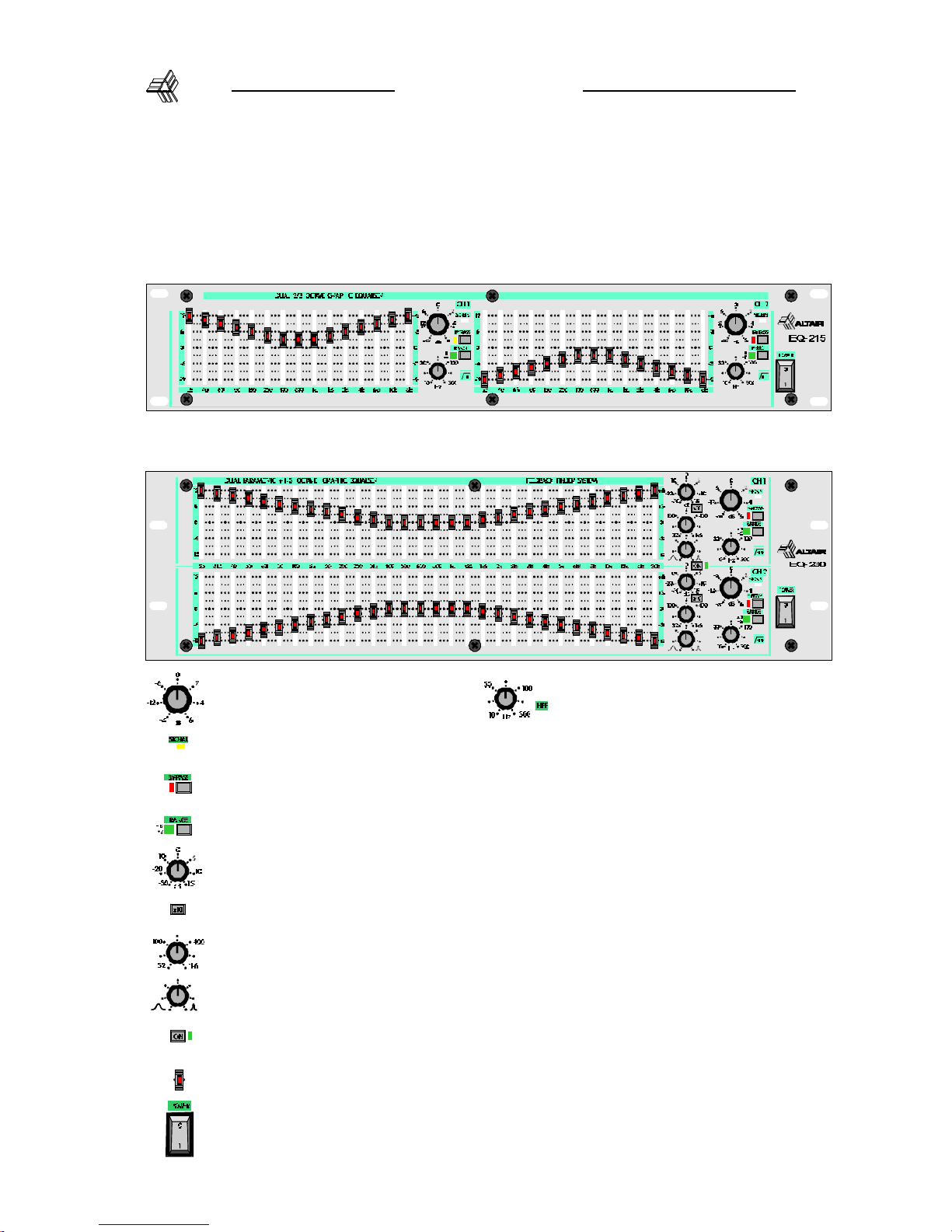
The graphic equalisers are designed for standard 19" rack mounting, and occupy 2u
(EQ-215) or 3u (EQ-230) rack space.
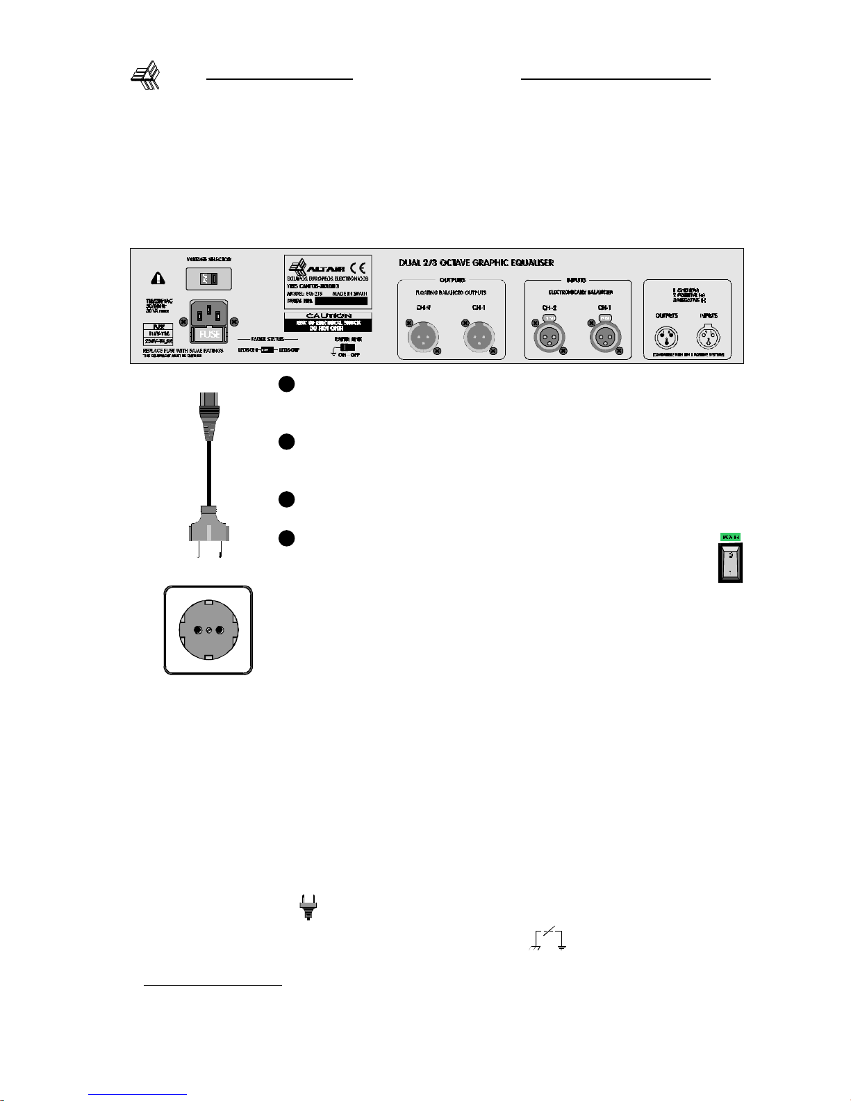
CHANGINGTHEVOLTAGE
The graphic equaliser unit is set to operate at 230VAC, 50-60Hz and at 115 VAC, 50-
60Hz. Unless specified the unit is set to 230 VAC.
Make sure that the graphic equaliser unit is disconnected from the mains.
6
ALTAiR EQ-215/230 GRAPHIC ECUALISERS
1