altitude 3500-ss User manual

ALTITUDE
3500 - SS
Integrated Valve Amplifier

Contents
1. Introduction
2. Important Notes
3. Va l v e s
4. Location & Ventilation
5. Front Panel
6. Rear Panel
8. Specifications
Caution:
To reduce the risk of electric shock,
Do Not Remove Cover.
Do not operate with Valves removed.
Refer servicing to qualified service personnel.
VALVE EQUIPMENT USES HIGH VOLTAGE
WARNING
Beware:
Keep out of reach of children
Keep away from flammable items
Keep away from moisture & water
Valves run hot.
! CAUTION !
RISK OF ELECTRIC SHOCK
DO NOT OPEN
High Voltage
! BEWARE !
DO NOT TOUCH WHILE ON
VALVES ARE HOT
Caution HOT!

ALTITUDE 3500-SS
Introduction
Congratulations for purchasing the Altitude A3500-SS Integrated Valve Amplifier.
The A3500-SS features a blend of quality components and wiring with the shortest
signal paths possible to ensure high definition wide bandwidth and low noise for digital
and analogue sound.
The circuit design lay out has been chosen carefully by our expert audio engineers after
years of development and refinement for reliability to ensure the highest quality of
musical reproduction with accurate and emotional delivery of the sound stage with
minimum distortion and maximum dynamic range.
Direct coupling techniques have been used on the double triode input stages to improve
signal transient response combined with hand selected wide bandwidth audio output
transformers coupling the Class A/B pentode output valves to the speakers.
The stainless steel panels between the mains power transformer and output valves
reduce the transformer running temperature and shield the output valves improving
over all amplifier efficiency
High quality electrolytic and non-electrolytic capacitors are used in the power supply
and in the critical signal areas to improve the bass midrange and top end transients.
The excellent blend of components used in this amplifier also enable very tight fast clean
low bass performance normally not found on valve amplifiers.
We recommend the use of high quality interconnects and speaker cables with the
Altitude A3500-SS Integrated Valve Amplifier to enable uncompromised sound quality
from your audio system equipment and speakers.
Enjoy a new dimension in sound.
1

ALTITUDE 3500-SS
Important notes
HEAT FROM THE AMPLIFIER
Do not touch the valves after the amplifier has been switched
on as the valves become very hot during operation and
should only be handled after the power has been turned off,
valves have cooled and high voltages have dissipated.
Allow about 15 to 20 minutes for the unit to cool down.
SUPPLY VOLTAGE
The A3500-SS has been factory set to the 240Vac~50Hz
mains voltage for Australia. The voltage setting is marked on
the rear panel and should be verified that it complies with
your local mains supply. Please use the IEC power cord
supplied with the unit. We recommend that you make all
other connections before applying power to the A3500-SS.
WATER & MOISTURE
As with any electrical equipment, these amplifiers should not be used near water or
moisture. Keep clear of open windows.
CLEANING THE AMPLIFIER
Turn off the power on the front panel of the amplifier and remove the power cable from
the mains wall socket completely before cleaning the panels.
We do not recommend the use of water, alcohol, chemicals, or cleaning sprays on any
part of the amplifier chassis or valves. Please wipe down with soft cotton cloth only.
Valves may become loose. Straighten by pressing down on each valve firmly into its base.
For details on this procedure, see “Replacing The Valves” on the next page.
DO NOT OPEN !
The user should not attempt to service the amplifier beyond that described in the
owner’s manual. No user serviceable parts inside. Dangerous voltages inside.
Please refer all servicing, other than valve maintenance, to a qualified Service Technician
at an Authorized Fountek Service Center. Valve amplifiers run on high voltages.
SHOCK HAZZARD !
DO NOT remove the cover of the amplifier.
High voltages are contained inside the unit.
DO NOT operate the amplifier with the valves removed.
Potential risk to both user and amplifier components.
KEEP OUT OF REACH OF CHILDREN
Valves get hot!
2

Valves
INSTALLING THE VALVES
Each EL34 valve has been tested, matched in pairs, then
custom installed into your A3500-SS. Internal bias
adjustments have been factory made specifically to suit.
The A3500-SS valves are then removed and individually
packaged for transportation. Therefore each EL34 Valve is
labeled with the appropriate socket number to aid
installation. The use of cotton gloves is advised.
Always ensure that power is removed before inserting or
removing valves. Remove each valve from its packaging and
insert it into the appropriate valve socket on the A3500-SS.
A key-way on the center shaft shows polarity of insertion.
Give a firm press to seat correctly. Be careful when handling
as valves are sensitive being made of glass and have filaments.
Proceed until all eight valves, large and small, are inserted.
VALVE LIFE & MAINTENANCE
If a valve is arcing, change immediately as it may damage other components.
Due to “Cathode Emission”, valve specifications can change marginally over time & use.
We recommend replacing the entire set after several years use or when the optimum
performance is no longer achieved.
OUTPUT VALVES EL34-EH
For the best music results, always replace valves with the original type Electro
Harmonics. Equivalent valves can be used, however performance is optimised for the
EL34-EH. It is also recommended that the full set of four be replaced at one time
otherwise imbalances in bias currents leading to over heating and shorter valve life can occur.
Also, Left & Right tone and overall sound quality may be compromised.
INPUT VALVES & PHASE SPLITTER VALVES.
For the best optimised results, always replace the input pre-amp valves and the phase
splitter valves with the original type Electro Harmonics 12AU7 & 12AT7.
REPLACING THE VALVES
Switch off the AC 240V power on the front panel of the amplifier.
Switch off the AC 240V at the wall and remove the power cord from the wall socket.
Allow around 20 minutes for the amplifier to cool down before replacing any valves.
This allows the valves to cool down and for capacitors to discharge.
To remove: Gently wiggle the valve whilst lifting it up vertically out of the valve socket.
To insert: When fitting the valve, make sure the pins on the new valve are all straight and
orientated in the correct direction so they line up with the holes in the valve socket on
the A3500-SS. The orientation of the valve is polorised by a key-way.
Ensure the valves are fitted into the valve socket firmly. Bases should be secured with no
visible gaps exposing the pins.
3

Location & Ventilation
Please Note. Valves do get hot.
Proper installation of your new Altitude A3500-SS
Integrated Valve Amplifier requires a stable location with
ample ventilation and protection from bumps & knocks, etc.
The A3500-SS is supplied with solid aluminium rounded feet
best suited for standing on its own shelf away from other
electronics, anything flammable, and open windows, etc.
Note: We recommend you do not install the valve amplifier
into a cabinet behind closed doors. The EL34 Valve generates
quite an amount of heat and requires ample ventilation.
Do not place the A3500-SS directly on thick pile carpet,
mats, towels or any type of surface that may restrict the
ventilation holes underneath the amplifier.
We recommend a minimum 100mm (4") of clearance on the top and around the sides of
the A3500-SS to allow for ample airflow and EL34 heat dissipation. A similar distance
from other electronics and speakers is also recommended for improved performance.
4

Front Panel
POWER
Centrally located on the front panel is the power switch.
Press power switch in to turn power ON and out to turn OFF.
An orange lamp will indicate and the valves will glow when Power is ON.
FUNCTION SWITCH
Selects audio inputs (1,2,3,4 ) CD / TUNER / AUX-1 / AUX-2
Gold plated relays will select the connected source.
An orange lamp will indicate the selected input.
INPUTS
Each A3500-SS input jack pair accepts Line Level Stereo connection to any
typical hi-fi system RCA outputs. Each input is labeled for your convenience.
All 4 inputs are electrically identical and only differ in how they are labeled.
1 - CD : CD / DVD / SACD players
2 - TUNER : AM / FM Stereo or Digital Radio Receiver
3 - AUX 1 : Phono Pre-amplifier (Optional External) or
Home Theatre Pre-amplifier Out (Mains L&R)
4 - AUX 2 : VCR, DV or Computer Sound Playback
VOLUME
Turn clockwise to set volume to your required listening level.
Turn down the Volume, fully anti-clockwise, before switching off the amplifier.
RUNNING
It is not recommended that you leave your amplifier permanently switched on.
This ultimately will only reduce valve and component life and waste electricity.
Your amplifier has solid state rectification to supply power, so the valves reach peak
operating condition quickly, approximately 30 to 60 minutes for optimised performance.
5
1234
Selector Volume
Power
ALTITUDE A3500-SS
INTEGRATED AMPLIFIER

Back Panel
MAINS POWER
POWER INPUT (IEC Socket) : IEC 240 V mains cord power input socket.
Insert the supplied IEC power cable, ensure a firm secure fitting.
FUSE: Mains fuse is located under the plastic cover below the IEC socket.
The A3500-SS has been factory set to the 240Vac~50Hz mains voltage for Australia..
The voltage setting is marked on the rear panel and should be verified that it complies
with your local supply. Please use the IEC power cord supplied with the unit.
We recommend that you make all other connections before applying power.
REPLACING THE FUSE: Be sure the unit is turned off and
remove the 240V IEC mains cable. Use a screw driver to open
the plastic cover located below the IEC socket. Replace the fuse
only with a recommended type (See Specifications for fuse value).
If the fuse continues to blow then please return your A3500-SS
to the place of purchase for attention. Faulty valves can be the
cause of a delayed fuse blow. Once the valve heats up, they falter
and then blow the fuse. Replacing all valves may be well advised.
Please see the Valve page for details on replacing valves.
MAINS FILTER POWER BOARDS are always a cost effective investment.
Your equipment is protected from electrical spikes and noise entering via the mains.
This effectively prolongs the units service life and also improves audio performance.
In locations where mains power fluctuates, an optional 240V Regulator & Power Filter
Unit between the 240V wall outlet and the power cord feed to the amplifier is advisable.
AMPLIFIER RUN-IN TIME
The Electro Harmonix valves, as supplied with the A3500-SS, are pre “run-in” to correct
specification at the factory. It is normal practice to allow a week or so of normal listening
to further run-in valves especially if you have changed them during a dealer service.
6
TUNER
AUX 1AUX 2
12
3
4
CD
240V A/C 50 HZ
POWER INPUT
FUSE
RIGHT
SPEAKER
4
OHM
8
OHM
LEFT
SPEAKER
4
OHM
8
OHM

SPEAKER CONNECTIONS
PLEASE NOTE!: Do not operate the amplifier with the speakers disconnected.
The A3500-SS is designed to run one pair of stereo speakers.
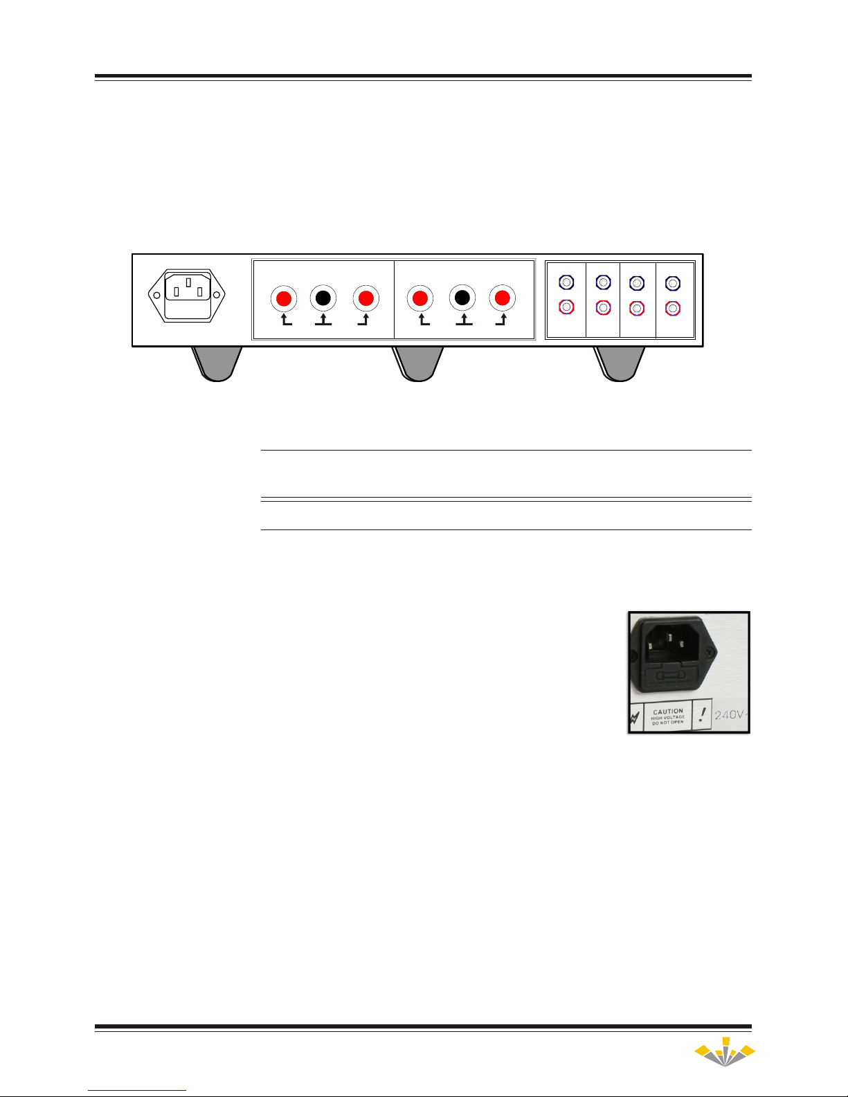
On the rear panel are six gold plated speaker terminal posts with screw locks.
These are for speaker cables with 4mm plugs or bare ended 8AWG (max) cable.
Connect 8 OHM speakers to the terminals marked 8 OHM and Common.
Connect 4 OHM speakers to the terminals marked 4 OHM and Common.
If you are unsure of the load then use the 4 OHM terminals.
Connect the speaker cable POSITIVE to the RED terminal (8 OHM or 4 OHM)
Connect the speaker cable NEGATIVE to the BLACK terminal (common)
Ensure that the Left and Right speakers are the correct way around as labeled.
Check that polarities between amplifier and speakers are correct for both channels.
Do not connect more than one pair of speaker cables to the A3500-SS terminals.
Do not connect speakers to both the 8 OHM and 4 OHM terminals.
SPEAKER CABLE WITH FITTED 4mm BANANA PLUGS
Insert the speaker plugs fully into the holes provided in the back of the terminals.
SPEAKER CABLE WITH BARE WIRE
Clean strip the ends of the speaker cable about 15mm (5/8"). Ensure that there are no
loose strands. Unscrew the speaker terminal cover anti clockwise to allow enough room.
Insert the bare ended speaker cable into the 4mm entry hole located on the side of each
speaker terminal. Accepts up to 8AWG cable thickness. We recommend premium cable.
Screw down the speaker terminal cover clockwise until the cable is secured firmly.
Do not use a wrench to tighten the speaker terminals as you may cause damage.
We recommend keeping cable distances to a minimum and to use high quality speaker
cable as the better the interconnects, the more detail you will hear from your equipment.
SPEAKER POSITION
To achieve optimum sound stage and depth of field, we recommend to position the left
and right speakers between 2.7 to 3.5 Metres apart and to angle both speakers in towards
the centre listening position by around 5 degrees. Avoid positioning the speakers too
close to an adjacent or back wall. A minimum distance of 0.25 to 0.75 Metres is advised.
Fine-tune the speaker’s position to suit your room acoustics using a known recording.
Please note that all rooms are different, so you may want to experiment with various
positions and orientations of your speakers until you are satisfied with the sound.
INPUT CONNECTIONS - RCA
There are four pairs of Gold plated RCA sockets for
connection to four audio sources.
Each pair is labeled corresponding to the front panel
selector switch and accepts Line Level Stereo
connection to any typical hi-fi system RCA outputs.
All 4 inputs are electrically identical and only differ
in how they are labeled. We recommend gold plated
premium quality audio leads be used for long and
reliable service. If you want to connect a turntable,
the A3500-SS requires an optional external phono
RIAA equalised pre-amp.
7

Specifications
The Altitude 3500-SS is an exclusive version specifically improved for the local market by Stones Sound Studios
on behalf of WES Australasia. Specifications are of actual production stock [independently tested sample]
and are correct at the time of printing. Specifications may change without notice.
CHANNELS:........................................................................................2 channel
INPUTS (x4): .................................................................CD / TUNER / AUX1 / AUX2 (1,2,3,4)
INPUT IMPEDANCE: ..............................................................................100K Ohms
INPUT SENSITIVITY: ......................................................................[375mV rms @ 1Khz]
INPUT CLASS .......................................................................................“A” Class
OUTPUT POWER 8ohm (per channel) ....................................................35 Watts @ 1 KHz 8ohm RMS
......................................................................................[32.50Wrms 0.63% THD]
OUTPUT POWER 4ohm (per channel) ....................................................30 Watts @ 1 KHz 4ohm RMS
......................................................................................[31.13Wrms 0.63% THD]
OUTPUT CLASS: ..........................................................................“A/B” Class (push pull)
OUTPUT: .....................................................................4 or 8 ohm speaker load ( 0-4-8 ohms )
T.H.D. ...............................................................................[0.63% @ 1KHz (245Vac)]
FREQUENCY RESPONSE: ...............................................................[15Hz- 50KHz +/- 0.5dB]
BANDWIDTH .........................................................................[<10 Hz to >90 kHz -3dB]
SLEW RATE: .....................................................................[1.36V/µs @ 1KHz Square Wave]
DYNAMIC RANGE: .........................................................................[82dB “A” Weighted]
NOISE: ..................................................................................[ -76.2dB at full power]
VALVES: ...........................................2 x 12AT7 Twin triode direct coupled input Electro-Harmonix 12AT7-EH
.......................................................2 x 12AU7 Twin triode phase splitter Electro-Harmonix 12AU7-EH
.................................................................4 x EL34 Pentode output Electro-Harmonix EL34-EH
...............................................................................EL34 Output Valves are matched pairs
FUSE: ..................................................................................240V 3.15A (Fast 2AG)
CHASSIS: ..............................................................Silver in Colour, 7mm thick Brushed Aluminum
DIMENSIONS: ..............................................................350mm(W) X 190mm(H) X 320mm(D)
.........................................................................................350x75mm Face Plate
NET WEIGHT: ........................................................................................18Kgs
GROSS WEIGHT: ......................................................................................21Kgs
8

Notes
9

Manufacturer:
Fountek Electronics Co., Ltd.
Australian R&D:
Stones Sound Studio.
P.O. Box 94
Tyalgum NSW 2484
Australia
Phone +61-02-66-793059,
Fax +61-02-66-793700
E-mail: russellstorey@bigpond.com
Exclusive Australian Distributor:
WES Australasia.
138 Liverpool Rd,
Ashfield. NSW 2131
Australia
Phone: +61-02-9716-0741
Fax: +61-02-9798-0017
E-mail: info@wes.net.au
Copyright © 2006. Print V4 - June 2006
Table of contents