Altman GALLERY SERIES User manual

*$//(5<6(5,(6/('/80,1$,5(6
,QVWDOODWLRQ8VHU¶V0DQXDO

Have a question regarding this manual?
The material in this manual is for information purposes only and is subject to change without notice. Altman
Lighting assumes no responsibility for any errors or omissions which may appear in this manual.
Should you find an error, have a suggestion or question regarding your Altman Lighting product, we would
love to hear from you.
You can reach us at:
Altman Lighting
57 Alexander Street
Yonkers, New York 10701
1.914.476.7987 (Main)
1.914.963.7304 (Fax)
www.altmanlighting.com
customerservice@altmanlighting.com
Note: Information contained in this document may not be duplicated in full or in part by any person without
prior written approval of Altman Lighting. Its sole purpose is to provide the user with conceptual information
on the equipment mentioned. The use of this document for all other purposes is specifically prohibited.
The material in this manual is for information purposes only and is subject to change without notice. Altman
Lighting assumes no responsibility for any errors or omissions which may appear in this manual. For
comments and suggestions regarding corrections and/or updates to this manual, please visit the Altman
Lighting web site at www.altmanlighting.com or contact your nearest Altman Lighting Regional Manager.
El contenido de este manual es solamente para información y está sujeto a cambios sin previo aviso.
Altman Lighting con no asume responsabilidad por errores o omisiones que puedan aparecer. Cualquier
comentario, sugerencia o corrección con respecto a este manual, favor de dirijirlo a la oficina de Altman
Lighting más cercana.
Der Inhalt dieses Handbuches ist nur für Informationszwecke gedacht, Aenderungen sind vorbehalten.
Altman Lighting uebernimmt keine Verantwortung für Fehler oder Irrtuemer, die in diesem Handbuch
auftreten. FürBemerkungen und Verbesserungsvorschlaege oder Vorschlaege in Bezug auf Korrekturen
und/oder Aktualisierungen in diesem Handbuch, moechten wir Sie bitten, Kontakt mit der naechsten
Altman Lighting Niederlassung aufzunehmen.
Our Commitment
Altman Lighting continually engages in research related to product improvement. New materials,
production methods and design refinements are introduced into existing products without notice as a
routine expression of the philosophy. For this reason any current Altman Lighting product may differ in
some respect from its published description, but will always equal or exceed the original design
specifications unless otherwise noted.
Document Number: 49-0230 (Rev. A)
Version as of: 14 September 2016
Gallery Series LED Luminaires Installation & User’s Manual
©2016 Altman Lighting. All rights reserved.

1
Gallery Series LED Luminaires Installation & User’s Manual
IMPORTANT INFORMATION
Product Safety Notices
Warnings
When using electrical equipment, basic safety precautions should always be followed including the
following:
a. READ AND FOLLOW ALL SAFETY INSTRUCTIONS.
b. Do not use outdoors unless the product is specified to operate in outdoor environments.
c. Do not mount near gas or electric heaters.
d. Equipment should be mounted in locations and at heights where it will not readily be
subjected to tampering by unauthorized personnel.
e. The use of accessory equipment not recommended by the manufacturer may cause an
unsafe condition.
f. Do not use this equipment for other than intended use.
g. Refer service to qualified personnel.
SAVE THIS MANUAL FOR FUTURE REFERENCE.
WARNING: You must have access to a main circuit breaker or other power
disconnect device before installing any wiring. Be sure that power is disconnected
by removing fuses or turning the main circuit breaker off before installation.
Installing the device with power on may expose you to dangerous voltages and
damage the device. A qualified electrician must perform this installation.
WARNING: Refer to National Electrical Code® and local codes for cable
specifications. Failure to use proper cable can result in damage to equipment or
danger to personnel.
WARNING: This equipment is intended for installation in accordance with the
National Electric Code® and local regulations. It is also intended for installation in
indoor applications only. Before any electrical work is performed, disconnect power
at the circuit breaker or remove the fuse to avoid shock or damage to the control. It is
recommended that a qualified electrician perform this installation.
WARNING: This Lighting Fixture IS NOT for residential installation or use.
THIS PRODUCT MUST BE INSTALLED IN ACCORDANCE WITH THE APPLICABLE
INSTALLATION CODE BY:
A PERSON FAMILIAR WITH THE CONSTRUCTION AND OPERATION OF THE
PRODUCT AND THE HAZARDS INVOLVED.
CE PRODUIT DOIT ÊTRE INSTALLÉ SELON LE CODE D'INSTALLATION PERTINENT,
PAR UNE PERSONNE

Installation & User’s Manual Gallery Series LED Luminairess
2Important Information
FCC NOTICE
This equipment has been tested and found to comply with the limits for a Class A digital device, pursuant
to part 15 of the FCC Rules. These limits are designed to provide reasonable protection against harmful
interference when the equipment is operated in a commercial environment. This equipment generates,
uses, and can radiate radio frequency energy and, if not installed and used in accordance with the
instruction manual, may cause harmful interference to radio communications.
Operation of this equipment in a residential area is likely to cause harmful interference in which case the
user will be required to correct the interference at his own expense.
Altman Lighting Product Warranty
Warranty Term
Altman Lighting, Inc., a subsidiary of Altman Stage Lighting Company, Inc., herein referred to as Altman,
warrants each new product (except for spare parts or products Altman does not manufacture) for a period
of TWO (2) years from date of shipment to correct by repair or replacement any part defect due to faulty
material or workmanship. Under these same terms products with an LED light source shall be warranted
for a period of THREE (3) years.
Altman warrants for NINETY (90) days any spare part it manufactures. On spare parts or products Altman
does not manufacture, including, but not limited to, lamps, sockets, lenses, roundels, electronics, ignitors,
ballasts, etc.; Altman will grant the same warranty given Altman by its vendors.
Altman assumes no responsibility for damage or faulty performance caused by misuse, improper
installation, careless handling or where repairs have been attempted by others.
This warranty is in lieu of all warranties or guarantees expressed or implied and no representative or
person is authorized to assume Altman any other liability with the sale of Altman’s products.
For complete warranty terms and conditions, please refer to our web site at www.altmanlighting.com.
Warranty Service
In order to request warranty service, you must receive a Return Material Authorization (RMA) number prior
to return.
Return shipments must be visibly marked with the RMA number; the product must be returned (shipping
prepaid) to the factory at:
Altman Lighting Inc.
Attention: RMA # ___________
57 Alexander Street
Yonkers, NY 10701
The return must be within THIRTY (30) days of receiving the RMA from Altman.

Altman Lighting Product Warranty 3
Gallery Series LED Luminaires Installation & User’s Manual
TABLE OF CONTENTS
Have a question regarding this manual? ............................................................ Inside Front Cover
Our Commitment ................................................................................................ Inside Front Cover
Important Information
Product Safety Notices ................................................................................................................... 1
Warnings ........................................................................................................................................ 1
FCC NOTICE ........................................................................................................................................ 2
Altman Lighting Product Warranty......................................................................................................... 2
Warranty Term................................................................................................................................ 2
Warranty Service ............................................................................................................................ 2
Table Of Contents
Preface
About this Manual ................................................................................................................................. 5
Product Descriptions ............................................................................................................................. 5
Accessories........................................................................................................................................... 5
Gallery Series LED Luminaires Lens Tubes & Gate....................................................................... 5
Gallery Series LED Luminaires Other Accessories ........................................................................ 5
Gallery Series LED Luminaires Overview
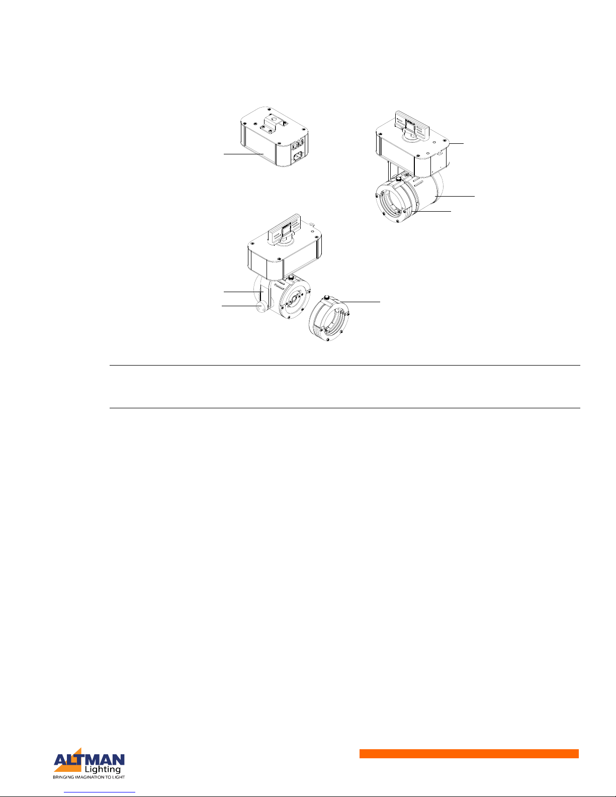
Gallery Series LED Luminaires Components........................................................................................ 6
Short and Long Zoom Luminaires .................................................................................................. 6
Beam Wash Luminaires ................................................................................................................. 6
Flood Luminaires ............................................................................................................................ 7
Installation and Set Up
Top Box Overview ................................................................................................................................. 8
Power Requirements............................................................................................................................. 9
Connecting Power................................................................................................................................. 9
MAINs Dimming Versions............................................................................................................... 9
Smart Track Mount Models .......................................................................................................... 10
0-10V Controlled Models (Sink Current)....................................................................................... 11
Canopy / Pendant Mount Models ................................................................................................. 12
Connecting to the DMX512 Network................................................................................................... 13
Connection Block Terminal........................................................................................................... 13
RJ45 / XLR Connectors ................................................................................................................ 14
Setting a DMX Address via RDM.................................................................................................. 14
Operation
Luminaire Features ............................................................................................................................. 16
Focus Button ................................................................................................................................ 16
Zoom Spot Models ....................................................................................................................... 16
Beam Wash Models ..................................................................................................................... 18
Flood Models ................................................................................................................................ 18
Accessory Holder - All Models...................................................................................................... 19
Pan & Tilt - All Models .................................................................................................................. 19
Cleaning and Care
Special Cleaning and Care Instructions .............................................................................................. 20
Lens Cleaning ..................................................................................................................................... 21
Front Lens (Exterior)..................................................................................................................... 21
Front Lens (Interior) ...................................................................................................................... 21
Service and Maintenance.................................................................................................................... 21

Installation & User’s Manual Gallery Series LED Luminairess
4Table Of Contents
Troubleshooting
Troubleshooting Guide ....................................................................................................................... 22
Technical Specifications
Gallery Series LED Luminaires Common Specifications.................................................................... 23
Gallery Series LED Luminaires Dimensions....................................................................................... 24
15 to 35 Degree Long Zoom Models............................................................................................ 24
25 to 50 Degree Short Zoom Models ........................................................................................... 24
Beam Wash Models ..................................................................................................................... 25
Flood Models................................................................................................................................ 25

About this Manual 5
Gallery Series LED Luminaires Installation & User’s Manual
PREFACE
About this Manual
The document provides installation and operation instructions for the following products:
• Gallery Series LED Luminaires
Please read all instructions before installing or using this product. Retain this manual for future reference.
Product Descriptions
This manual covers the all Gallery Series LED Luminaires models. Because these fixtures are configured
at the time of ordering, please refer to the current product specification sheet for the model numbers and
descriptions.
Accessories
Contact your Authorized Altman Lighting Dealer for price and availability of all accessories for Gallery
Series LED Luminairess. Additional information can be found on the Altman Lighting web site at
www.altmanlighting.com.
Gallery Series LED Luminaires Lens Tubes & Gate
* Specify color at time of ordering by adding the following code for color: B = Black or W = White.
Gallery Series LED Luminaires Other Accessories
* Specify color at time of ordering by adding the following code for color: B = Black or W = White.
** All portable units use RJ45 Connectors for DMX connectivity. For connectivity to any DMX 5-pin system, you will need part num-
bers RJ45F-DMXF and RJ45F-DMXM.
Part Number Description
GAL2550LT * Additional 25o- 50o Short Zoom Lens Tube (note, requires Gate Assembly GALGALT)
GAL1535LT * Additional 25o- 50o Long Zoom Lens Tube (note, requires Gate Assembly GALGALT)
GALFLLT * Additional 85o Flood Lens Tube
GALBWLT * Additional 15o- 60o Beam Wash Lens Tube
GALGALT * Additional Gate Assembly (note, required for zoom fixtures)
Part Number Description
61-0265 RAD (Remote Addressing Device) for addressing fixtures via RDM. Required for DMX
models.
MSC Spare Mini Safety Cable (included with fixture)
GALTH * Gallery Series Top Hat
GALHTH * Gallery Series Half Top Hat
GALBD * Gallery Series Barn Doors
GALGH Gobo Holder - E Size (37.5mm OD) / Image Area is 28mm
GALCF * Gallery Series Color Frame
RJ45F-DMXF ** RJ45 Female to DMX 5-Pin Female
RJ45F-DMXM ** RJ45 Female to DMX 5-Pin Male
DMX-MPHX-TERM DMX Terminator

Installation & User’s Manual Gallery Series LED Luminairess
6Gallery Series LED Luminaires Overview
GALLERY SERIES LED LUMINAIRES OVERVIEW
Gallery Series LED Luminaires Components
Short and Long Zoom Luminaires
Figure 1 shows the basic features of Short and Long Zoom Gallery Series LED Luminaires.
Figure 1: Short and Long Zoom Luminaire Features
Beam Wash Luminaires
Figure 2 shows the basic features of Beam Wash Gallery Series LED Luminaires.
Figure 2: Beam Wash Luminaire Features
Top Box (portable models) Top Box (track models)
LED Engine
Yoke Arm
Yoke Tilt Knob
Zoom Lens Tube
Gate Assembly
(with shutters)
Zoom Lens Tube
Gate Assembly
(with shutters)
LED Engine
Refer to "Top Box Overview" on
page 8 for more information.
Top Box (portable models)
Top Box (track models)
LED Engine
Yoke Arm
Yoke Tilt Knob
Beam Wash Lens
Beam Wash Lens
LED Engine
Refer to "Top Box Overview" on
page 8 for more information.

Gallery Series LED Luminaires Components 7
Gallery Series LED Luminaires Installation & User’s Manual
Flood Luminaires
Figure 3 shows the basic features of Flood Gallery Series LED Luminaires.
Figure 3: Flood Luminaire Features
Note: The features illustrated in this section is to familiarize users with the basic components and features
of the fixtures. The next chapters will provide detailed information on connections and mounting. For
technical specifications, refer to "Technical Specifications" on page 23.
Top Box (portable models)
Top Box (track models)
LED Engine
Yoke Arm
Yoke Tilt Knob
Flood Lens
Flood Lens
Refer to "Top Box Overview" on
page 8 for more information.

Installation & User’s Manual Gallery Series LED Luminairess
8Installation and Set Up
INSTALLATION AND SET UP
Top Box Overview
There are several mounting configurations for the Gallery Series LED Luminaires:
• Portable - C-Clamp / Unistrut
• Smart Track / Track
• Ceiling / Pendant
The model(s) purchased determines how the unit can be mounted. Figure 4 shows the features and
connections on the two versions of the Gallery Series Luminaire top boxes.
Figure 4: Top Box Overview - Features
C-Clamp / Unistrut Mounting Point
(mounting hole 1/2-in. / 12.7 mm)
IEC Connection (AC Input)
DMX In / Out
(RJ45 connections)
Track Adapter
Safety Cable Anchor Point
(same for all models)
Ceiling Mount
Portable Models C-Clamp / Unistrut
Smart Track / Track Mount Models
Ceiling / Pendant Mount Models
Pendant Mount
NOTES:
Only top boxes shown for clarity.
Top boxes are not removable and cannot be
remotely located.

Power Requirements 9
Gallery Series LED Luminaires Installation & User’s Manual
Power Requirements
WARNING! The Gallery Series LED Luminaires should be connected to a constant circuit or a relay
device. It should never be connected to a dimmer or circuit controlled by a dimmer unless the unit is
specifically designed to do so (MAINS dimming models - 120VAC only). Read this section carefully on how
to properly connect your fixture.
WARNING! All Gallery Series LED Luminaires are shipped prewired from the factory. The wiring
information in Table 1 is shown for field wiring information and must be performed by a qualified and
licensed electrician. Before performing any field wiring, refer to and read the warnings contained in
"Important Information" on page 1.
Connecting Power
Units are powered in one of two ways depending on the model(s) purchased.
• Direct connection to a AC power source for the portable unit via their IEC to Edison input cable (Portable
models that are mounted with a C Clamp or Unistrut).
• Direct connection to the powered track (Track Mount / Smart Track Models or Ceiling / Pendant Models)
Field wiring of the fixture is straight forward. A total of three wires/conductors need to be brought to the
unit. The following wiring scheme, as shown in Table 1, is required for direct connection models.
Table 1: AC Input Wiring
IMPORTANT! All Gallery Series LED Luminaires must be connected to and properly grounded to an
viable earth ground.
MAINs Dimming Versions
Gallery Series LED Luminaires are available in a 120VAC Mains Dim version which is achieved with
standard TRIAC-Based incandescent dimmers (see Table 2, “Compatible Mains Dimmers,” on
page 10) that “chop” the AC voltage or with standard ELV (electronic low-voltage) dimmers.
Figure 5: Phase Cut Sine Wave Example
Wire Color (120V Models) Purpose
Black Main / (L)ine
White (N)eutral
Green Ground / Earth
Wire Color (100 - 240VAC Models) Purpose
Brown Main / (L)ine
Blue (N)eutral
Green/Yellow Ground / Earth
Normal AC Sine Wave
Phase Cut AC Sine Wave
(from source to dimmer)
(from dimmer to fixture)

Installation & User’s Manual Gallery Series LED Luminairess
10 Installation and Set Up
Table 2: Compatible Mains Dimmers
WARNING! Phase-Cut Dimmers are only available for 120VAC systems. The use of any other type of
dimmer will damage the unit and void the product’s warranty. Table 2 represents a number of
manufacturers dimmers that have been tested with the product. As this list represents some of the larger
dimmer manufacturers it is recommended when utilizing an alternate dimming manufacturer that the
Gallery Series Luminaire is tested with any alternate dimmer prior to utilization. Please note that the
majority of phase-cut dimmers tested have resulted in proper dimming performance. For additional
information, please contact customer service.
Smart Track Mount Models
To connect Smart Track models to track:
Step 1. If not done at factory, connect AC wiring as shown in Figure 6. Also refer to Table 1 on page 9.
Figure 6: Track Adapter Power Wiring
Compatible Phase-Cut, 120VAC Dimmers
Manufacturer Dimmer Model Manufacturer Dimmer Model
Lutron
S-603PG
Leviton
IP-106-1LZ
DVCL-153P 6631-2
DV-600P VPE06
TGCL-153P 6683-IW
S-600P 6161
DVELV-303P 6633-P
SELV-300P IPE04
TG-600P Cooper DLC03P
CT-103P SLC03P
MAELV-600 DAL06P
FAELV-500 Philips Strand
Lighting
C21 350uS
Lightolier ZP260QEW A21 IGBT
ETC D Series A21 SCR
Main / Line Neutral
Ground / Earth

Connecting Power 11
Gallery Series LED Luminaires Installation & User’s Manual
Step 2. As shown in Figure 7, connect fixture to track as follows:
Figure 7: Installing Fixture on Track
a. Turn Knob A Clockwise 90 Degrees for physical mechanical attachment.
b. Turn Knob B Clockwise 90 Degrees for circuit #1 power
c. Turn Knob B Counterclockwise 90 Degrees for circuit #2 power.
IMPORTANT! Ensure that the track head is fully seated into the track prior to moving to the next step.
Portable Models
Portable models are supplied with a locking IEC power input connector. Similar to other electronic devices.
This type of connector is used due to its reliability and inability to cross the main / neutral / ground
connections. IEC ac input cables are readily available through most electrical /electronic retailers around
the world.
Note: Some models are MAINs dimmable models. These units are for 120VAC markets only and a list of
approved dimmers is listed in Table on page 13.
To connect power to portable models:
Step 1. Make sure the AC cable is not connected to an AC power source.
Step 2. As illustrated in Figure 8 on page 11, position AC input cable in direct relation to the IEC
connector on the side luminaire top box assembly.
Figure 8: IEC Connector - Portable Models
Step 3. Press AC input cable IEC connector firmly into IEC connector on top box assembly.
Step 4. The luminaire is now ready to connect to an AC source.
0-10V Controlled Models (Sink Current)
Gallery Series LED Luminaires’ 0-10V drivers only operate with dimmers that sink current. They are not
designed to operate with 0-10V controls systems that source current, as used in theatrical and
entertainment systems. Developed in the 1980’s, the 0-10V sinking current controls method is adopted by
the International Electrotechnical Commission (IEC) as apart of the IEC 60929 Annex E standard.
Note: Luminaire not
shown for clarity.
Portable Model Top Box
IEC Connector (AC Input)
NOTES:
Luminaire not shown for clarity.
Top boxes are not removable and cannot be
remotely located.

Installation & User’s Manual Gallery Series LED Luminairess
12 Installation and Set Up
The method to dim the output current of the driver is done via the +Dim/-Dim signal lines. This input
responds to a 0-10V signal, delivering 1%-100% of the output for the luminaire.
Compatible 0-10V Dimmers include but are not limited to:
• Lutron: Nova Series
• Lutron: Diva Series
• Leviton: Illuma Tech Series.
IMPORTANT! As all 0-10 Volt dimmers offer different features and options please consult the dimmer
manufacturers wiring guide for additional information when wiring to 0-10V operated Gallery Series LED
Luminaires.
Wiring - Power and 0-10V Control
Figure 9: 0-10V and Power Wiring
Canopy / Pendant Mount Models
Note: Ceiling junction box and junction box screws are not included with Gallery Series LED Luminaires
and are by others.
WARNING! Canopy / pendant mount models must be installed by qualified professional installer and
should be done in accordance with local and national codes.
To wire and install canopy / pendant mounted models:
WARNING! Make sure power to the junction box is completely disconnected. Failure to do so could lead
to serious injury or death.
Step 1. Install Gallery Series LED Luminaires Mounting Flange to ceiling junction box.
Step 2. Connect wiring to fixture. Refer to "Connecting Power" on page 9 or "0-10V Controlled Models
(Sink Current)" on page 11 as applicable.
Table 3: 0-10V Wiring
For power wiring, refer to Table 1, “AC Input
Wiring,” on page 9.
Wire Color Signal
Purple Dim - Positive (+)
Gray Dim - Negative (-)
Power Wiring0-10V Control Wiring (Dim)
Gray (Dim -)
Purple (Dim +) Black or Brown (Line)
White or Blue (Neutral)
Green or Green/Yellow
(Ground / Earth)

Connecting to the DMX512 Network 13
Gallery Series LED Luminaires Installation & User’s Manual
Step 3. Align fixture bottom mounting flange with top mounting flange screws.
Figure 10: Canopy / Pendant Mount
Step 4. Turn clockwise securing the unit to top mounting flange.
Step 5. Tighten flange screws.
Connecting to the DMX512 Network
DMX controlled models offer either a connection block (Figure 11) inside the luminaire’s canopy or
pendant mount or via on-board RJ45 connectors for portable units (refer to "Top Box Overview" on page
8 and "RJ45 / XLR Connectors" on page 14).
Basic DMX512 installation consists of connecting multiple DMX controlled Gallery Series LED Luminaires
together (up to 32 Total devices per DMX string) in “daisy-chain” fashion or Track application. A cable runs
from the DMX512 control source to the DMX INPUT connection on the first luminaire. From the DMX
OUTPUT of the luminaire another cable runs to the DMX IN connector on the next luminaire (or DMX512
device to be controlled).
IMPORTANT! At the end of each DMX Daisy chain, it is highly recommended that a DMX TERMINATOR
(Altman Lighting part number DMX-MPHX-TERM for the connectors shown in Table 4) is utilized on the
last luminaire (or device) in the chain.
For more information on installing DMX512 control systems, the following publication is available for
purchase from the United States Institute for Theatre Technology (USITT), “Recommended Practice for
DMX512: A Guide for Users and Installers, 2nd edition” (ISBN: 9780955703522). USITT Contact
Information: www.usitt.org
Connection Block Terminal
For direct connections, refer to Table 4 and Figure 11 on page 14.
Notes:
• All pin information is read from left to right from the back of the connector (looking at wiring inlet).
Bottom Mounting Flange
Top Mounting Flange
(mounts to junction box)
Flange Screw (x2)
Table 4: DMX Connector Block Wiring
DMX
Connection Wire Color Signal Factory
Wired Connection Customer
Connection Connection
DMX Input
White / Orange Data In (+)
Male
Pin 1 (Left)
Female
Pin 3 (Right)
Orange Data In (-) Pin 2 (Center) Pin 2 (Center)
White / Brown Data In (Common) Pin 3 (Right) Pin 1 (Left)
DMX Output
White / Green Data Out (+)
Female
Pin 1 (Left)
Male
Pin 3 (Right)
Green Data Out (-) Pin 2 (Center) Pin 2 (Center)
Brown Data Out (Common) Pin 3 (Right) Pin 1 (Left)

Installation & User’s Manual Gallery Series LED Luminairess
14 Installation and Set Up
• (DMX Version Ceiling mount) One (1) piece of Category 5 Belden 1592A cable for all data connectivity.
Three (3) of the conductors are used for data input and three (3) conductors for data output. Note, the
White/Blue & Blue conductors are not used. Both Data Input and Output utilize a Phoenix Contact 3
position terminal block for use with 20-24 AWG.
Figure 11: DMX Connector Wiring
RJ45 / XLR Connectors
For models with RJ45 connectors for DMX Input / Output, refer to Table 5 for RJ45 and XLR connector
wiring.
Note: * Only those pins shown are used. Remaining pins on RJ45 and XLR connectors are not used.
Setting a DMX Address via RDM
Gallery Series LED Luminaires are full featured Remote Device Management (RDM) compliant. All DMX
and Luminaire settings are programmed via a RDM ANSI E1.20 complaint device. As many of the RDM
devices and software work differently please consult the RDM programmer manufacturer for specific
Table 5: DMX RJ45 & XLR Connector Wiring
DMX Connections - RJ45 and XLR Connectors
DMX Signal RJ45 Connector* XLR Connector*
Common (Drain) Pin 7 Pin 1
DMX - Pin 2 Pin 2
DMX + Pin 1 Pin 3
(A) Insert and hold small, flat screwdriver
into slot to open wire way.
(B) Insert CAT 5 DMX cable into wire
way. Strip wire to 0.25-in / 6.5 mm.
DMX INPUT
DMX OUTPUT
White / Green (Data Out +)
Green (Data Out -)
Brown (Data Out Common)
Pin 1
Pin 2
Pin 3
White / Green (Data Out +)
Green (Data Out -)
Brown (Data Out Common)
Pin 3
Pin 2
Pin 1
Pin 1
Pin 2
Pin 3
Pin 3
Pin 2
Pin 1
White / Orange (Data In+)
Orange (Data In -)
White / Brown (Data In Common)
White / Orange (Data In+)
Orange (Data In -)
White / Brown (Data In Common)
Factory (Fixture) Wiring Customer (Building) Wiring

Connecting to the DMX512 Network 15
Gallery Series LED Luminaires Installation & User’s Manual
operational instructions. Table 6 on page 15 shows the list of the settings and features that can be set via
RDM.
Note: The entire DMX infrastructure must be RDM compliant in order to achieve system-wide RDM
functionality.
Setting a DMX Address via RAD
The Remote Addressing Device (model RAD, sold separately, refer to "Gallery Series LED Luminaires
Other Accessories" on page 5 for ordering information) is used to set the DMX address of Gallery Series
LED Luminaires (DMX Versions) using DMX/RDM. RDM (Remote Device Management) is an
enhancement to DMX512 which allows status information and parameters (such as the DMX address) to
be communicated over the DMX LAN.
Note: If you do not have a RAD, a RDM compliant console / device that is capable of addressing, can also
be used to set the DMX address.
To set the DMX address using RAD:
Step 1. Connect RAD to the fixture(s) to be addressed using standard DMX cabling.
Note: If there are any isolators or splitters in between the RAD and the device(s) they must be capable of
bi-directional communication per the RDM Standard.
Step 2. Press NEXT button on RAD.
Step 3. One of the RDM devices will be discovered and identify itself.
Step 4. RAD’s display will show identified device’s DMX address. Identification method varies from device
to device many lighting fixtures flash or strobe.
Step 5. Use RAD’s three buttons below the display to change DMX address of identified device.
Step 6. After a few seconds after the address has been changed, RAD’s display will flash as new DMX
address is sent to device.
Step 7. Press NEXT button to identify another device and set its address (repeat addressing steps).
Step 8. LAST button is used to move back through the previously identified devices.
Step 9. Pushing NEXT button, with no more devices to be found, will display three dashes ( - - - ).
Note: If no buttons are pressed on the RAD for about 15 seconds, the RAD will go into sleep mode. In this
battery saving mode, one segment will flash on the display. To wake the RAD from sleep, push any of the
buttons or cycle the power switch.
Table 6: DMX Addressing
Item Value Additional Values
RDM Protocol Version 0100
Device Model ID LED Driver 40W
Product Category Specialized LED Dimmer
Boot Version 0.00
Software Version ID V000001.12
DMX 512 Start Address 1 (default) Settings between 1 and 512
DMX Foot Print 1 (default)
Manufacturer Label Altman
Dimming Curve Linear (default) Logarithmic

Installation & User’s Manual Gallery Series LED Luminairess
16 Operation
OPERATION
Luminaire Features
This section will cover the unique features of the various models. Some features - as described in this
section - may or may not be applicable to all models. Each section will let you know what models this
feature is applicable to a fixture or series of fixtures.
Focus Button
Each DMX Model is equipped with a “focus button” located on the top box assembly on the luminaire head
side. This button is programmed for full on/off control of the luminaire whether DMX is active or inactive.
Pressing this button will bring the luminaire to full, if off or off, if at full. If the DMX system is active and the
DMX Value is changed from its current value, the prevailing DMX signal will then take control of the
luminaire.
Note: Any change in the DMX value will over ride the focus button (last action takes precedence).
Zoom Spot Models
Gallery Series LED Luminaires fitted with a short or long zoom lens, has the following features:
• User-settable and lockable zoom and focus control
• 4-blade shutter system (set on two planes)
• Gobo slot for E-size gobos measuring 37.5 mm OD with a 28 mm image area. Gobo holder is included
with all zoom spot models and can be purchased as an additional accessory.
• End of lens tube accessory holder (same for all models, see "Accessory Holder - All Models" on page
19)
Zoom and Focus Control
Zoom and focus is easily accomplished by the two knobs located on the zoom spot lens tube. The front
knob (towards the end of the lens tube) controls the fixture’s zoom / beam angle. The rear knob (closest to
the LED engine) controls the focus of the beam. Refer to Figure 12.
To change the fixture’s beam angle, simply loosen (do not remove) the zoom / beam angle knob and set as
desired. Re tighten by hand once desired beam angle is achieved. Repeat this for the focus of the fixture.
Note: Keeping the lens knobs loose and slightly snug will allow smooth movement of the lenses along the
lens tube when making adjustments. Loosening the knobs too much will make fine/precision adjustments
difficult and may misalign the lenses and give poor focus adjustment through the focus range.
DMX
Models
Zoom Spot
Models
Zoom Spot
Models

Luminaire Features 17
Gallery Series LED Luminaires Installation & User’s Manual
Figure 12: Zoom Spot Models - Beam Control
4-Blade Shutter
Gallery Series LED Luminaires with zoom spot lenses have a gate assembly that contains four-blade
shutters that can be moved by hand in and out of the beam for shutter cuts. The can moved as needed
either straight out (or in) or at an angle. Figure 13 shows the gate and the four shutter blade handles.
Figure 13: Zoom Spot Models - Shutter Blades
Side of Luminaire
Bottom of Luminaire
(A)
Notes:
(A) Focus Knob
(B) Zoom / Beam Angle Knob
(C) All zoom lens tubes are equipped with a graduated scale.
15 - 35 Degree Zoom Basic Settings
(B)
(C)
25 - 50 Degree Zoom Basic Settings
Front of Luminaire
Narrow (25 Degrees)
Wide (50 Degrees)
Front of Luminaire
Narrow (15 Degrees)
Wide (35 Degrees)
Zoom Spot
Models
Note: Luminaire shown in exploded view for clarity. Track
model shown, same for all zoom spot models.
Shutter Blade (x4)
Lens Tube
Gate Assembly*
LED Engine
Gobo Slot
* Gate Assembly Notes:
• Gate Assembly must be installed with shutter blades
closest to lens tube for proper focusing and optimal
performance.
• Gate Assembly can rotate 360 degrees for gobo or
shutter cuts.

Installation & User’s Manual Gallery Series LED Luminairess
18 Operation
Gobo Slot
Gallery Series LED Luminaires with zoom spot lenses offer a gobo slot (Figure 13) to hold one E-size
gobo with the dimensions of 37.5 mm OD with a 28 mm image area. Gobo holder is included with all zoom
spot models and can be purchased as an additional accessory.
IMPORTANT! Please note that some gobos, depending upon their reflectivity level may need to be
blackened in order to obtain superior projections. Additional beam shaping is obtained through the four (4)
integrated shutters.
Beam Wash Models
Beam wash models offer a variable beam angle of 15 to 60 degrees and a end of lens accessory holder
(see "Accessory Holder - All Models" on page 19 for more information on the accessory holder).
Beam Angle Adjustment
Gallery Series LED Luminaires that have the beam wash lens are designed and are ideal to project a soft
edge, even beam of light. For beam wash models, beam shaping is achieved through external, four-flap
barn doors (sold separately).
To adjust the beam angle, simply loosen, do not remove, the beam angle knob as illustrated in Figure 14.
Once the desired angle is achieved, re-tighten the beam angle knob.
Note: Keeping the beam angle knob loose and slightly snug will allow smooth movement of the lens along
the lens tube when making adjustments. Loosening the knob too much will make fine/precision
adjustments difficult and may misalign the lens.
Figure 14: Beam Wash Models - Beam Angle Adjustment
Flood Models
Flood models offer a fixed beam angle of 85 degrees and a end of lens accessory holder (see "Accessory
Holder - All Models" below for more information on the accessory holder). For flood models, beam
shaping is achieved through external, four-flap barn doors (sold separately).
Zoom Spot
Models
Beam Wash
Models
Beam Wash
Models
Beam Angle Knob
Front of Luminaire
Beam Wash Basic Settings
Spot Position (15 Degrees)
Flood Position (60 Degrees)
Flood
Models
Other manuals for GALLERY SERIES
1
Table of contents
Popular Home Lighting manuals by other brands

Safavieh Lighting
Safavieh Lighting TBL4176A quick start guide

Philips
Philips 37235/48/16 user manual

Daylight
Daylight Ultimate D21098 instructions

Safavieh Lighting
Safavieh Lighting LAMBER TBL4418 manual

Safavieh Lighting
Safavieh Lighting Elli LIT4012A quick start guide

ROTHFELS
ROTHFELS 1575060 quick start guide