Alto Professional ZMX164FXUSB User manual

QUICKSTART GUIDE
ENGLISH ( 3 – 7 )
MANUAL DE INICIO RÁPIDO
ESPAÑOL ( 8 – 12 )
GUIDE D’UTILISATION RAPIDE
FRANÇAIS ( 13 – 17 )
GUIDA RAPIDA
ITALIANO ( 18 – 22 )
KURZANLEITUNG
DEUTSCH ( 23 – 27 )
SNELSTARTGIDS
NEDERLANDS ( 28 – 32)


3
volume
m1
m2
pitch xyz
-
+
octave
accomp store
tap
phrase latch
analogmodeling synth
push
r
h
y
t
h
m
s
p
a
t
t
e
r
n
s
p
r
o
g
r
a
m
s
s
e
t
u
p
s
c
o
n
f
i
g
QUICKSTART GUIDE (ENGLISH)
BOX CONTENTS
yZEPHYR mixer
yPower cable
yUSB cable
yQuickstart Guide
ySafety Instructions & Warranty Information booklet
CONNECTION DIAGRAM
Power
Headphones*
Booth monitors*
Keyboard*
Computer*
Microphones*
External effects rack,
compressor, etc.*
Lamp*
House amp and
speakers*
Stage monitors*
External effects rack,
compressor, etc.*
TOP PANEL
REAR PANEL
* Microphones, monitors, amplifier, speakers, cables, etc. are not included.

4
REAR PANEL FEATURES
1
5
6
7
8
1. POWER IN – Use the included power adapter to connect the mixer to a power outlet. While the power is
switched off, plug the power supply into the mixer first, then plug the power supply into a power outlet.
2. POWER SWITCH – Turns the mixer on and off. Turn on the mixer after all input devices have been connected
and before you turn on amplifiers. Turn off amplifiers before you turn off the mixer.
3. PHANTOM POWER – Activates/deactivates phantom power. When activated, phantom power supplies +48V
to the XLR mic inputs. Please note that most dynamic microphones do not require phantom power, while most
condenser microphones do. Consult your microphone’s documentation to find out whether it needs phantom
power.
4. MAIN MIX OUTPUTS – Use standard XLR and 1/4" cables to connect these outputs to the house speaker or
amplifier system. The level of these outputs is controlled by the MAIN MIX FADER.
5. MAIN OUTPUT LEVEL – Use this button to match the appropriate input level of a device connected to the
MAIN MIX OUTPUTS. When the button is depressed, the main mix will be reduced by 30 dB. When the
button is raised, the main mix will be boosted by 4 dB.
6. MAIN INSERT – Use standard 1/4" TRS cables to connect these jacks to external processors (such as
compressors, limiters, external EQ units, etc.). The audio sent out of these jacks is taken after the EQ. The
audio is returned to these jacks before the MAIN MIX FADER.
7. MONO OUTPUT VOLUME – Controls the level of the MONO OUTPUT.
8. MONO OUTPUT – This output is a summed mono version of the audio sent out of the MAIN MIX OUTPUTS.
Use a standard 1/4" TS cable to connect this jack to an external device (such as a monitor, recording device,
etc.).
9. CTRL OUTS – Use standard 1/4" cables to connect these outputs to your monitor or amplifier system. The
level of these outputs is controlled by the CTRL ROOM VOLUME knob.
10. DFX OUT – This output sends out audio from the mixer's effects processor. Use a standard 1/4" TS cable to
connect this jack to an external device (such as a monitor, recording device, etc.). Adjust the level of the audio
with the EFFECTS OUT knob.
11. FOOTSWITCH – When a latching-style footswitch is connected to this jack with a 1/4" TRS cable, it can be
used to mute/unmute the mixer's effects processor.
12. USB PORT – Use a standard USB cable to connect the mixer to a computer. This port can send or receive
different kinds of audio over the USB connection, depending on the position of the USB RECORD and USB
PLAYBACK switches.
13. USB RECORD – When a computer is connected to the mixer's USB PORT, you can send audio from the mixer
to the computer for recording. Set this switch to "SUB1/2" to record the audio sent out of SUBGROUPS OUT 1
and 2. Set it to "MAIN MIX" to send the main mix to the computer.
14. USB PLAYBACK – When a computer is connected to the mixer's USB PORT, you can send audio from the
computer to the mixer. Set this switch to "CH15/16" to send it to Channels 15/16. (Make sure the INPUT
SELECTOR for Channel 15/16 is set to "USB.") Set the switch to "MAIN MIX" to send it directly to the main
mix.
15. AUX SEND – Use 1/4" TRS cables to connect these outputs to the inputs of an external amplifier or active
monitor. You can adjust these levels with the AUX SENDS VOLUME knobs to create a custom monitor mix for
onstage musicians.
16. AUX RTN (RETURN) – Connect the outputs of an external device to these inputs with 1/4" mono cables. This
is usually used for outboard effects devices but can also be used like an extra input channel for synthesizers,
drum machines, etc. If your source is mono, plug it into the left jack and it will be heard on both the left and
right sides.
17. DIRECT OUT – Use standard 1/4" TS cables to connect any of these outputs to an external device for
recording, monitoring, etc. each individual channel.
18. SUBGROUPS OUT – Use standard 1/4" TS cables to connect any of these outputs to an external device for
recording, monitoring, etc. each individual subgroup.
19. SUBGROUPS INSERT – Use standard 1/4" TRS cables to connect these jacks to external processors such as
compressors, limiters, external EQ units, etc. The audio sent out of these jacks will be the subgroup stereo
signal. The audio is returned to these jacks before the subgroups faders.

5
TOP PANEL FEATURES
Note: The channels have essentially the same controls with some minor variations between Channels 1-8, 11-12, 15-
16. The three different channel types are shown here.
1. MIC INPUT – Connect a microphone to these inputs with
an XLR cable.
2. LINE INPUT – Connect line-level devices to these inputs
with 1/4" cables.
3. INSERT – Use a standard 1/4" TRS cable to connect an
external processor (such as a compressor, limiter, external
EQ unit, etc.) to this jack. The signal will be taken after the
channel's gain control and returned before the channel's
EQ controls.
4. GAIN – Adjusts the channel audio level (pre-fader and
pre-EQ gain). Adjust this so that the PEAK LED just
barely lights up during the loudest parts of the song.
5. LOW CUT FILTER – When this button is depressed, that
channel's audio will be sent through a 75 Hz low-
frequency filter with a slope of 18 dB per octave. This is
useful for reducing hum and other low-frequency noise
when using microphones.
6. HI EQ (TREBLE) – Adjusts the high (treble) frequencies of
the channel.
7. MID EQ – Adjusts the mid-range frequencies of the
channel.
8. MID FREQUENCY SELECTOR – Adjusts the frequency
band affected by the MID EQ knob.
9. LOW EQ (BASS) – Adjusts the low (bass) frequencies of
the channel.
10. AUX SEND CHANNEL VOLUME – Adjusts the audio level
sent from that channel to the Aux Channel (which is sent
out the AUX SENDS and controlled by the AUX SENDS
VOLUME knobs). The top two knobs can adjust the pre-
or post-fader levels (as determined by the AUX PRE-
/POST-FADER SWITCH). The bottom knob can adjust
the level of the signal sent to the mixer's effects processor.
11. AUX PRE-/POST-FADER SWITCH – When the button is
depressed, the audio sent to the corresponding AUX
SENDS is taken before the channel's fader. When the
button is raised, the audio sent to the AUX SENDS is
taken after the channel's fader.
12. CHANNEL PAN / BALANCE – If this knob is labeled
"PAN," it adjusts the (mono) channel's position in the
stereo field. If the knob is labeled "BAL," it adjusts the
balance between the two mono channels of that stereo
signal.
13. PEAK LED – The LED will flash if the signal is clipping. If
this happens, decrease the setting of the GAIN knob or
CHANNEL FADER.
14. CHANNEL FADER – Adjusts the audio level on the
channel.
15. CHANNEL MUTE – Press this button to mute/unmute the
channel. The channel's audio will only be sent to its
INSERT or heard in the Solo Channel when its SOLO
button is depressed.
16. CHANNEL ASSIGNMENT – Use these buttons to send
the channel to a subgroup, multiple subgroups, and/or the
main mix. Subgroup levels are controlled by the
SUBGROUP VOLUME FADERS; the main mix level is
controlled by the MAIN MIX FADER.
17. SOLO – When this button is depressed, the audio will be heard in the Solo Channel, which will become the
only audio sent to the PHONES OUTPUT and CTRL OUTS. The LED METERS will also display the audio
levels, which are controlled by the PHONES and CTRL ROOM volume knobs.
11
222
322
1
555
1
12 12
444
61
61
6
1
71
71
7
1
81
81
8
1
91
91
9
1
10 1
10 1
10
1
10 1
10 1
10
11
11 11
12
1
10
1
10
1
10
1
10
1
10
1
10
13 13 13
1
14 1
14 1
14
15 15 15
16
16
16
16
16
16
16
16
16
17 17 17

6
31
30
38
19
20
18
18
19
21
21
22 23
24 25
26 27
28
29
39
39 42
43
44
44
44
44
45
46
23
32
32
32
32
33
33
33
33
34
34
34
34
35
35
36
37
37 37
39
39
39
39
39
39
40 40 40 40 41
47
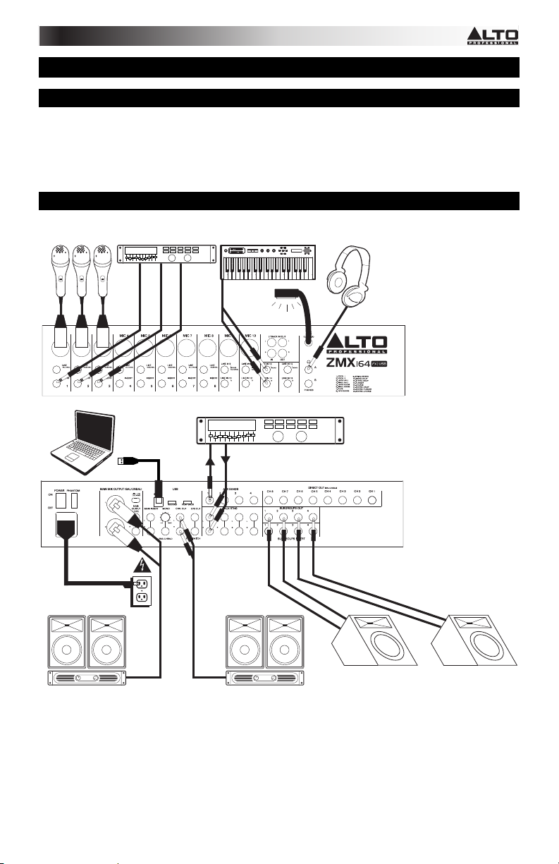
18. 2-TRACK INPUTS – You may connect these
inputs to the outputs of an external sound source
using a standard stereo RCA cable (sold
separately). You can send this channel to the
Solo Channel (using the CTRL ROOM SOURCE
"2 TK IN" switch) and/or the main mix (using the
2TK TO MIX switch).
19. 2-TRACK OUTPUTS – Connect these outputs to
the inputs of an external recording device using
a standard stereo RCA cable (sold separately).
20. LAMP – Connect a gooseneck lamp (12 V, 0.5
A, not included) to this BNC connector.
21. PHONES OUTPUT – Connect 1/4" stereo
headphones to these outputs. The PHONES
VOLUME knob controls the volume.
22. EFFECTS OUT VOLUME – Adjusts the volume
of the audio sent out of the DFX OUT from the
mixer's effects processor.
23. AUX 1/2 – Adjusts the level of the audio sent
from the effects processor out AUX SENDS 1
and 2.
24. EFFECTS SELECTOR – Selects the effect that
the mixer's internal effects processor will apply to
the various channels. Each channel can send
different levels of audio to the processor by
adjusting their FX POST SEND knobs. See the
EFFECTS section for an explanation of the
available effects.
25. VARIATIONS SELECTOR – Selects the amount
of the effect applied to the various channels.
26. FX MUTE – Press this button to mute/unmute
the effects.
27. FX PEAK LED – The LED will flash if the signal
is clipping. If this happens, decrease the setting
of the EFFECTS OUT knob. When the effects
processor is muted, the LED will be solidly lit.
28. POWER LED – Illuminates when the mixer is on.
29. PHANTOM POWER LED – Illuminates when the
PHANTOM POWER switch is on.
30. EQ ON/OFF – Enables or disables the
GRAPHIC EQUALIZER.
31. GRAPHIC EQUALIZER – When the EQ
ON/OFF switch is on (depressed), you can use
these controls to adjust the equalization of the
main mix.
32. AUX SENDS VOLUME – Controls the audio
level sent out the AUX SENDS.
33. AUX SENDS SOLO – When this button is
depressed, the audio signal being sent to the
AUX SENDS will also be routed to the Solo
Channel, which will become the only audio sent
to the PHONES OUTPUTS and CTRL OUTS.
The LED METERS will also display the audio
levels, which are controlled by the PHONES and
CTRL ROOM volume knobs.
34. AUX RTN VOLUME – Controls the audio level sent into the AUX RTN inputs.
35. AUX RTN TO AUX SEND VOLUME – Controls the audio level sent from the AUX RTN inputs back into the
Aux Channel.
36. AUX RTN 3 ROUTING SWITCH – Selects whether the AUX RTN 3 audio is routed to the CTRL ROOM mix
(when the button is depressed) or the main mix (when the button is raised).
37. AUX RTN 4 ROUTING SWITCHES – When these buttons are depressed, the AUX RTN 4 audio will be routed
to Subgroup 1 and 2, Subgroup 3 and 4, and/or the main mix.
38. AUX RTN SOLO – When this button is depressed, all AUX RTN audio will be heard in the Solo Channel, which
will become the only audio sent to the PHONES OUTPUTS and CTRL OUTS. The LED METERS will also
display the audio levels, which are controlled by the PHONES and CTRL ROOM volume knobs.
39. SUBGROUPS ASSIGN TO MAIN – Use these buttons to assign each subgroup's left and right channels to the
main mix. When a button is pressed, that channel is being routed to the main mix.

7
40. SUBGROUPS VOLUME – Use these faders to adjust the volume levels of each subgroup. The subgroups'
audio will be sent out their respective SUBGROUPS OUTS. When a subgroup has any of its ASSIGN TO
MAIN buttons depressed, its audio will also be sent to the main mix.
41. MAIN MIX FADER – Adjusts the volume of the MAIN MIX OUTPUTS.
42. SOLO MODE – Selects whether the Solo Channel is pre-fader ("PFL," when the button is raised) or post-fader
("AFL," when the button is depressed).
43. LED METERS – Shows the audio level of the main mix or the Solo Channel (when a channel's SOLO button is
depressed). The CLIP LED can light up occasionally, but if it happens too often, reduce the volume of the mix
and/or individual channels.
44. CONTROL ROOM SOURCE – Use these buttons to assign which channels are sent to the CTRL OUTS – the
main mix, Subgroups 1 and 2, Subgroups 3 and 4, and/or the 2 TRACK IN signal.
45. 2TK TO MIX – When this button is depressed, the 2 TRACK OUT audio will be added to the main mix.
46. PHONES VOLUME – Adjusts the volume of PHONES output.
47. CTRL ROOM VOLUME – Adjusts the volume of the CTRL OUTS.
EFFECTS
TO HEAR THE EFFECTS ON A CHANNEL: Use the EFFECTS SELECTOR to choose one of the effects below,
adjust the parameter with the VARIATIONS SELECTOR, then turn up the AUX SEND 2 CHANNEL VOLUME for that
channel.
# PRESET DESCRIPTION PARAMETER RANGE
1 VOCAL 1 Reverb, simulating a room with a small delay time. Decay time
Pre-delay
0.8~1.1s
0~79ms
2 VOCAL 2
Reverb, simulating a small space with a slight
decay time.
Decay time
Pre-delay
0.8~2.5s
0~79ms
3 LARGE HALL Reverb, simulating a large acoustic space. Decay time
Pre-delay
3.6~5.4s
23~55ms
4 SMALL HALL Reverb, simulating the acoustics of a stage space. Decay time
Pre-delay
1.0~2.9s
20~45ms
5 LARGE ROOM
Reverb, simulating a studio with many early
reflections.
Decay time
Pre-delay
2.9~4.5s
23~55ms
6 SMALL ROOM Reverb, simulating a bright studio room. Decay time
Pre-delay
0.7~2.1s
20~45ms
7 PLATE Simulates bright plate reverb. Decay time
Pre-delay
0.6~6.1s
10ms
8 TAPE REVERB
Simulates classic tape delay created by multiple
playback heads.
Decay time
Pre-delay
1.3~5.4
0~84ms
9 SPRING REVERB
Simulates the lightly stretched sound of spring
reverb from analog transducers.
Decay time
Pre-delay
1.3~5.4s
0~84ms
10 MONO DELAY Reproduces the signal after a small period of time. Delay period 60~650ms
11 STEREO DELAY
Reproduces the signal after a small period of time
with a slight difference between the two stereo
channels.
Delay period
Feedback
210~400ms
37~73%
12 FLANGER
Classic stereo flanging effect, similar to a jet plane
taking off. Rate 0.16~2.79Hz
13 CHORUS
Simulates the full, complex, watery sound of several
instruments playing the same thing. Rate 0.5~5Hz
14 REVERB+DELAY Delay effect with room reverb.
Delay period
Reverse decay
time
211~375ms
1.0~2.9s
15 REVERB+FLANGER Stereo flanger effect with room reverb.
Flanger rate
Reverse decay
time
0.16~2.52Hz
16 REVERB+CHORUS Stereo chorus effect with room reverb.
Chorus rate
Reverse decay
time
0.5~4.74Hz
1.5~2.9s

33
TECHNICAL SPECIFICATIONS
MONO INPUT CHANNELS
•Microphone inputs: Electronically balanced, discrete input configuration)
•Frequency response: 20Hz to 20kHz, +/-1dB
•THD+N: <0.03% at 0dBu, 1kHz
•Gain range: 0 dB to 50 dB (MIC)
•SNR (Signal to Noise Ratio): 114 dB
LINE INPUTS
•Electronically balanced
•Frequency response: 20Hz to 20kHz, +/-1dB
•THD+N: <0.03% at 0dBu, 1kHz
•Sensitivity range: -15 dBu to 35 dBu
IMPEDANCES
•Microphone inputs: 1.4 kΩ
•Channel insert return: 2.5 kΩ
•All other inputs: > 10 kΩ
•2-Track outputs: 1 kΩ
•All other outputs: 120 Ω
EQUALIZATION
•High-shelving: ±15 dB @ 12 kHz
•Mid bell (mono): ±12 dB (frequency range 100 Hz ~ 8 kHz)
•Low-shelving: ±15 dB @ 80 Hz
•Main EQ: 9 EQ bands (63Hz, 125Hz, 250Hz, 500Hz, 1kHz, 2kHz, 4kHz, 8kHz, 16kHz)±15 dB
DSP SECTION
•A/D & D/A converters: 24-bit
•DSP Resolution: 24-bit
•Effects: Large Hall, Medium Hall, Large Room, Medium Room, Karaoke, Short Spring
Reverb, Long Spring Reverb, Chamber, Mono Delay, Mono Echo, Stereo Echo, Flanger,
Chorus, Reverb + Chorus, Reverb + Delay, Thickener
•Presets: 16
•Controls: 16-position preset selector, 16-position variation selector, DSP mute switch, peak
LED indicator
MAIN MIX
•Noise (bus noise): Fader 0 dB, channels muted: -90 dBr (ref: +4 dBu) Fader 0 dB, all input
channels assigned & set to unity gain: -88 dBr (ref: +4 dBu)
•Phantom Power:Mic Pin2/Pin3 and Pin1 47±2V
POWER SUPPLY
•Main voltage: USA/Canada: 100-120 VAC ~ 60 Hz, UK/Australia: 240 VAC ~ 50 Hz, Europe:
210-240 VAC ~ 50 Hz
•Power consumption: 70 W
•Fuse: T1.6 AL
•Main connection: Standard IEC receptacle
DIMENSIONS (W x D x H)
•525 mm x 400 mm x 115 mm; (20.6” x 15.7” x 4.5”)
WEIGHT
•7.40 Kg (16.3 lb)
* Specifications are subject to change without notice.
Other Alto Professional Music Mixer manuals

Alto Professional
Alto Professional TMX80 DFX User manual

Alto Professional
Alto Professional RMX508DFX User manual

Alto Professional
Alto Professional LIVE2404 User manual

Alto Professional
Alto Professional TrueMix 600 User manual

Alto Professional
Alto Professional ZMX124FXUSB User manual

Alto Professional
Alto Professional ZEPHYR ZMX52 User manual

Alto Professional
Alto Professional ZMX244FXUSB User manual