4
PRODUCT DESIGN 3. Conversionkitsfor high altitude natural or propane gas
operation are available. See High Altitude Derate chart
fordetails.
4. Installer must supply the following gas line fittings, de-
pendingonwhichentrance is used:
Left -- Two 90º Elbows, one close nipple, straight pipe.
Right --Straightpipetoreachgasvalve.
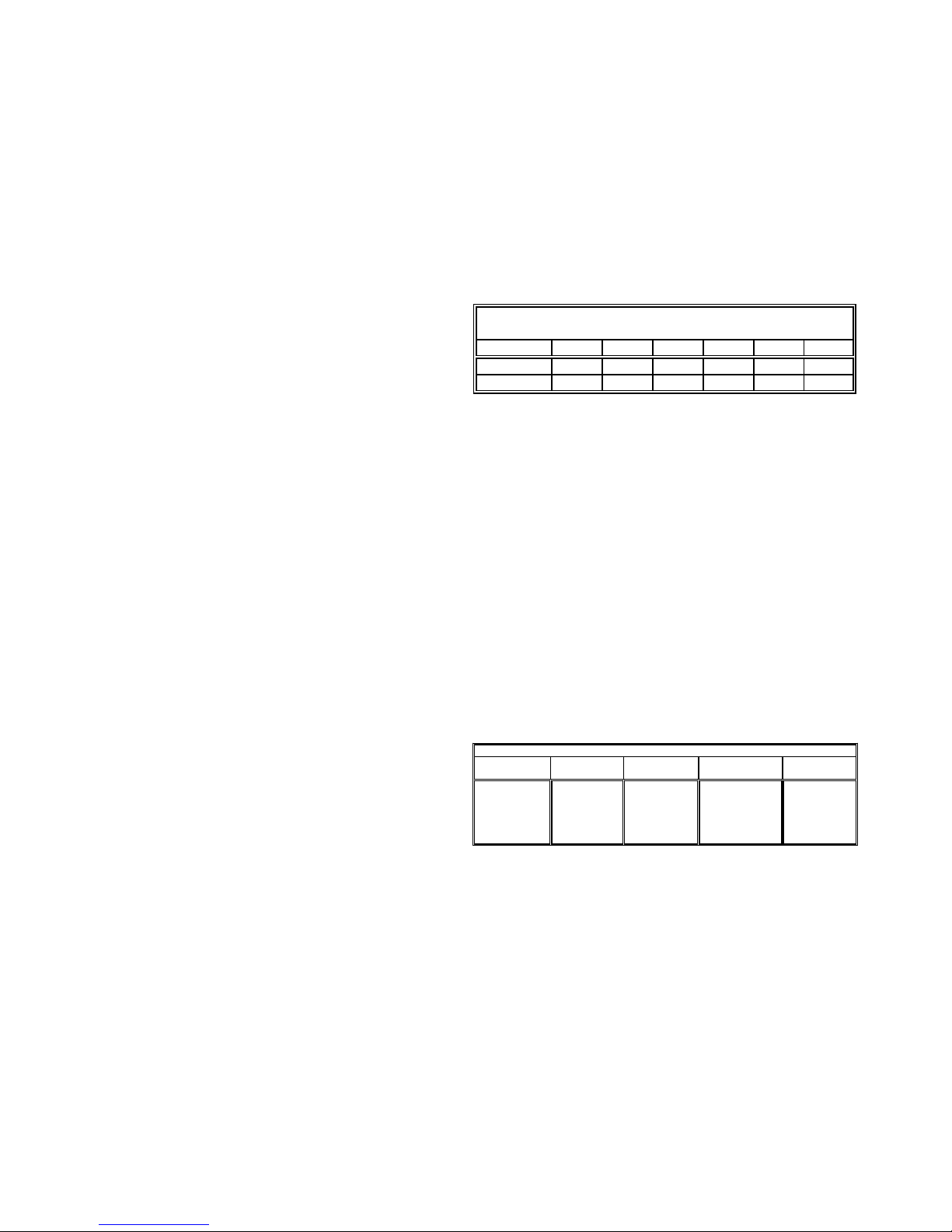
Accessibility Clearances (Minimum)
POSITION* FRONT SIDES REAR TOP FLUE FLOOR
Upflow30010C
Horizontal 3 6 0 6 0 C
*= All positioning is determined as installed unit is viewed from the front.
C= If placed on combustible floor, floor MUST be wood only.
MINIMUM CLEARANCES TO COMBUSTIBLE MATERIALS
(INCHES)
NC= For instalaltion on non-combustible floors only. A non-combustible
subbase must be used for installations on combustible flooring.
24"atfrontisrequiredforservicingorcleaning.
Note: Inallcases accessibility clearance shall take prece-
denceoverclearancesfromtheenclosure whereaccessibil-
ityclearancesaregreater. Alldimensionsaregivenininches.
High Altitude Derate
Whenthisfurnaceisinstalled at high altitude, the appropri-
ate High Altitude orifice kit must be installed. This is re-
quiredduetothenaturalreduction in the density of both the
gas fuel and combustion air as altitude increases. The kit
will provide the proper design certified input rate within the
specifiedaltituderange.
MODEL
NUMBER 0 to
7,000 ft. 7,001 to
9,000 ft. 9,001 to
11,000 ft. 7,001 to
11,000 ft.
AMH95*****XA*
LPM-051
LPM-062
Propane
Conversion Kit
(#55 Orifices)
HANG11
High Altitude
Natural Gas Kit
(#44 Orifices)
HANG12
High Altitude
NaturalGas Kit
(#45 Orifices)
HALP 10
High Altitude
LP Gas Kit
(#56 Orifices)
PROPANE AND HIGH ALTITUDE KITS
1LPM-05* supports White-Rodgers 2-stage valves only
2LPM-06* supports Honeywell and White-Rodgers 2-stage valves
High altitude kits are purchased according to the installa-
tionaltitudeandusageofeithernaturalorpropanegas.Refer
tothechartabovefor a tabular listing ofappropriatealtitude
rangesandcorrespondingmanufacturer’shighaltitudeNatu-
ralGasandPropaneGas kits. For a tabularlistingofappro-
priatealtituderangesandcorrespondingmanufacturer'sHigh
Altitude Pressure Switch kits, refer to either the Pressure
Switch Trip Points & Usage Chart in this manual or the Ac-
cessoryChartsinServiceInstructions.
GeneralOperation
The AMH95 furnaces are equipped with an electronic igni-
tion device used to light the burners and an induced draft
blowertoexhaust combustion products.
Aninterlockswitchpreventsfurnaceoperationiftheblower
door is not in place. Keep the blower access door in place
exceptforinspectionandmaintenance.
This furnace is also equipped with a self-diagnosing elec-
tronic control module. In the event a furnace component is
notoperatingproperly, thecontrolmoduleLED will flashon
and off in a factory-programmed sequence, depending on
theproblemencountered.Thislightcanbeviewedthrough
theobservationwindowinthebloweraccessdoor.Referto
theTroubleshootingChartfor furtherexplanationofthe LED
codesandAbnormal Operation - IntegratedIgnitionControl
section in the Service Instructions for an explanation of the
possibleproblem.
Theratedheatingcapacityofthefurnace should be greater
thanorequal to the total heat loss of the area tobeheated.
The total heat loss should be calculated by an approved
methodorinaccordancewith“ASHRAEGuide”or “Manual
J-LoadCalculations”published bytheAirConditioning Con-
tractors of America.
*Obtain from: American National Standards Institute 1430
BroadwayNewYork,NY10018
LocationConsiderations
• The furnace should be as centralized as is practical
with respect to the air distribution system.
• Donotinstallthefurnacedirectly on carpeting, tile, or
combustiblematerialotherthanwoodflooring.
• When suspending the furnace from rafters or joists,
use 3/8" threaded rod and 2” x 2” x 3/8” angle as
shownintheInstallationandServiceInstructions.The
length of the rod will depend on the application and
clearancenecessary.
• When installed in a residential garage, the furnace
mustbepositioned sotheburnersandignition source
are located not less than 18 inches (457 mm) above
the floor and protected from physical damage by ve-
hicles.
Notes:
1. Installermustsupply oneortwoPVCpipes:oneforcom-
bustionair(optional)and onefortheflueoutlet(required).
Ventpipemustbeeither 2” or 3” indiameter,depending
uponfurnaceinput,number of elbows, lengthofrunand
installation (1 or 2 pipes). The optional Combustion Air
Pipeisdependentoninstallation/coderequirements and
must be 2” or 3” diameter PVC.
2. Linevoltagewiring canenterthroughthe rightorleftside
ofthefurnace.Lowvoltagewiring can enter through the
rightorleftside of furnace.