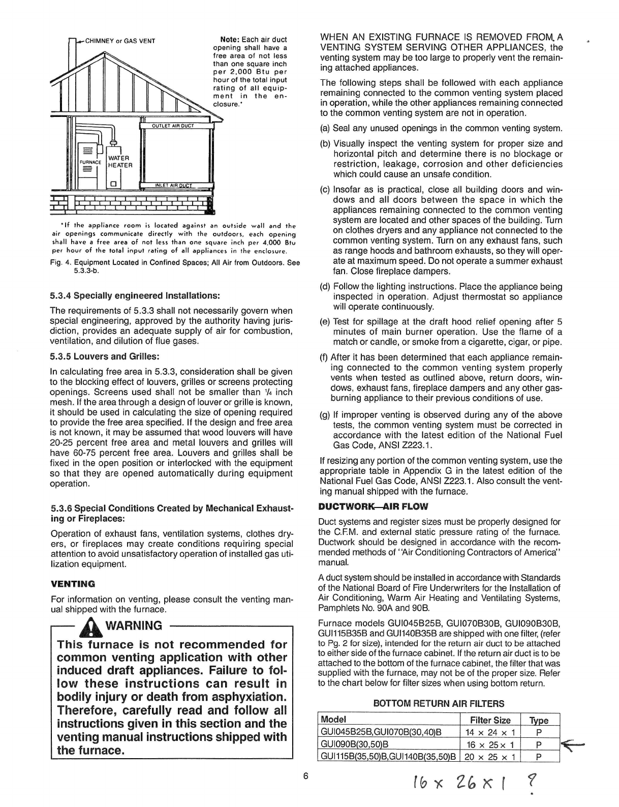
CHIMNEY
or
GAS
VENT
Note:
Each
air
duct
opening
shall
have
a
free
area
of
not
less
than
one
square
inch
per
2,000
Btu
per
hour
of
the
total
input
rating
of
all
equip-
ment
in
the
en-
closure.'
'If
the
appliance
room
is
located
against
an
outside
wall
and
the
air
openings
communicate
directly
with
the
outdoors,
each
opening
shall
have
a
free
area
of
not
less
than
one
square
inch
per
4,000
Btv
per
hour
of
the
total
input
rating
of
all
appliances
in
the
enclosure.
Fig.
4.
Equipment
Located
in
Confined
Spaces;
All
Air
from
Outdoors.
See
5.3.3-b.
5.3.4
Specially
engineered
Installations:
The
requirements
of
5.3.3
shall
not
necessarily
govern
when
special
engineering,
approved
by
the
authority
having
juris-
diction,
provides
an
adequate
supply
of
air
for
combustion,
ventilation,
and
dilution
of
flue
gases.
5.3.5
Louvers
and
Grilles:
In
calculating
free
area
in
5.3.3,
consideration
shall
be
given
to
the
blocking
effect
of
louvers,
grilles
or
screens
protecting
openings.
Screens
used
shall
not
be
smaller
than
1
/
4
inch
mesh.
If
the
area
through
a
design
of
louver
or
grille
is
known,
it
should
be
used
in
calculating
the
size
of
opening
required
to
provide
the
free
area
specified.
If
the
design
and
free
area
is
not
known,
it
may
be
assumed
that
wood
louvers
will
have
20-25
percent
free
area
and
metal
louvers
and
grilles
will
have
60-75
percent
free
area.
Louvers
and
grilles
shall
be
fixed
in
the
open
position
or
interlocked
with
the
equipment
so
that
they
are
opened
automatically
during
equipment
operation.
5.3.6
Special
Conditions
Created
by
Mechanical
Exhaust-
ing
or
Fireplaces:
Operation
of
exhaust
fans,
ventilation
systems,
clothes
dry-
ers,
or
fireplaces
may
create
conditions
requiring
special
attention
to
avoid
unsatisfactory
operation
of
installed
gas
uti-
lization
equipment.
VENTING
For
information
on
venting,
please
ual
shipped
with
the
furnace.
®
WARNING
consult
the
venting
man
-
This
furnace
is
not
recommended
for
common
venting
application
with
other
induced
draft
appliances.
Failure
to
fol-
low
these
instructions
can
result
in
bodily
injury
or
death
from
asphyxiation.
Therefore,
carefully
read
and
follow
all
instructions
given
in
this
section
and
the
venting
manual
instructions
shipped
with
the
furnace.
WHEN
AN
EXISTING
FURNACE
IS
REMOVED
FROM,A
VENTING
SYSTEM
SERVING
OTHER
APPLIANCES,
the
venting
system
may
be
too
large
to
properly
vent
the
remain-
ing
attached
appliances.
The
following
steps
shall
be
followed
with
each
appliance
remaining
connected
to
the
common venting
system
placed
in
operation,
while
the
other
appliances
remaining
connected
to
the
common
venting
system
are
not
in
operation.
(a)
Seal
any
unused
openings
in
the
common
venting
system.
(b)
Visually
inspect
the
venting
system
for
proper
size
and
horizontal
pitch
and
determine
there
is
no
blockage
or
restriction,
leakage,
corrosion
and
other
deficiencies
which
could
cause
an
unsafe
condition.
(c)
Insofar
as
is
practical,
close
all
building
doors
and
win-
dows
and
all
doors
between
the
space
in
which
the
appliances
remaining
connected
to
the
common
venting
system
are
located
and
other
spaces
of
the
building.
Turn
on
clothes
dryers
and
any
appliance
not
connected
to
the
common
venting
system.
Turn
on
any
exhaust
fans,
such
as
range
hoods
and
bathroom
exhausts,
so
they
will
oper-
ate
at
maximum
speed.
Do
not
operate
a
summer
exhaust
fan.
Close
fireplace
dampers.
(d)
Follow
the
lighting
instructions.
Place
the
appliance
being
inspected
in
operation.
Adjust thermostat
so
appliance
will
operate
continuously.
(e)
Test
for
spillage
at
the
draft
hood
relief
opening
after
5
minutes
of
main
burner
operation.
Use
the
flame
of
a
match
or
candle,
or
smoke
from
a
cigarette,
cigar,
or
pipe.
(f)
After
it
has
been
determined
that
each
appliance
remain-
ing
connected
to
the
common
venting
system
properly
vents
when
tested
as
outlined
above,
return
doors,
win-
dows,
exhaust
fans,
fireplace
dampers
and
any
other
gas
-
burning
appliance
to
their
previous
conditions
of
use.
(g)
If
improper
venting
is
observed
during
any
of
the
above
tests,
the
common
venting
system
must
be
corrected
in
accordance
with
the
latest
edition
of
the
National
Fuel
Gas
Code,
ANSI
Z223.1.
If
resizing
any
portion
of
the
common venting
system,
use
the
appropriate
table
in
Appendix
G
in
the
latest
edition
of
the
National
Fuel
Gas
Code,
ANSI
Z223.1.
Also
consult
the
vent-
ing
manual
shipped
with
the
furnace.
DUCTWORK
—AIR
FLOW
Duct
systems
and
register
sizes
must
be
properly
designed
for
the
C.F.M.
and
external
static
pressure
rating
of
the
furnace.
Ductwork
should
be
designed
in
accordance
with
the
recom-
mended
methods
of
"Air
Conditioning
Contractors
of
America"
manual.
A
duct
system
should
be
installed
in
accordance
with
Standards
of
the
National
Board
of
Fire
Underwriters
for
the
Installation
of
Air
Conditioning,
Warm
Air
Heating
and
Ventilating
Systems,
Pamphlets
No.
90A
and
90B.
Furnace
models
GU1045B25B,
GU1070B30B, GU1090B30B,
GU1115B35B
and
GUI140B35B
are
shipped
with
one
filter,
(refer
to
Pg.
2
for
size),
intended
for
the
return
air
duct
to
be
attached
to
either
side
of
the
furnace
cabinet.
If
the
return
air
duct
is
to
be
attached
to
the
bottom
of
the
furnace
cabinet,
the
filter
that
was
supplied
with
the
furnace, may
not
be
of
the
proper
size.
Refer
to
the
chart
below
for
filter
sizes
when
using
bottom
return.
BOTTOM
RETURN
AIR
FILTERS
_Model
Filter
Size
Type
GU1045B25B,GU1070B(30,40)B
14
x
24
x
1
P
GU1090B(30,50)B
_
16
x
25x
1
P
GUI115B(35,50)B,GU1140B(35,50)B
20
x
25
x
1
P
6