manuals.online logo
Brands
  1. Home
  2. •
  3. Brands
  4. •
  5. Amana
  6. •
  7. Furnace
  8. •
  9. Amana GUX-X User manual

Amana GUX-X User manual

Other manuals for GUX-X

1

This manual suits for next models

5

Other Amana Furnace manuals

Amana EGHW Installation instructions

Amana

Amana EGHW Installation instructions

Amana GULA Guide

Amana

Amana GULA Guide

Amana AMH95 Series User manual

Amana

Amana AMH95 Series User manual

Amana AMV9 User manual

Amana

Amana AMV9 User manual

Amana *MSS96 Series User manual

Amana

Amana *MSS96 Series User manual

Amana MVC80 User manual

Amana

Amana MVC80 User manual

Amana MES80 User manual

Amana

Amana MES80 User manual

Amana AM9S80 User manual

Amana

Amana AM9S80 User manual

Amana AM9S96 User manual

Amana

Amana AM9S96 User manual

Amana *CVC96 User manual

Amana

Amana *CVC96 User manual

Amana M9S96 Series User manual

Amana

Amana M9S96 Series User manual

Amana AMS81405DN User manual

Amana

Amana AMS81405DN User manual

Amana AMH950453BXA Series User manual

Amana

Amana AMH950453BXA Series User manual

Amana MES96 U Series User manual

Amana

Amana MES96 U Series User manual

Amana AMVM97 Operating instructions

Amana

Amana AMVM97 Operating instructions

Amana GUIA070A30 Operating instructions

Amana

Amana GUIA070A30 Operating instructions

Amana AMH8 User manual

Amana

Amana AMH8 User manual

Amana xMVC96 series User manual

Amana

Amana xMVC96 series User manual

Amana CVM97 Series User manual

Amana

Amana CVM97 Series User manual

Amana M9C96 Series User manual

Amana

Amana M9C96 Series User manual

Amana LPM-10 User manual

Amana

Amana LPM-10 User manual

Amana MEC80 Series User manual

Amana

Amana MEC80 Series User manual

Amana AMVS80-U User manual

Amana

Amana AMVS80-U User manual

Amana AMVS96-U User manual

Amana

Amana AMVS96-U User manual

Popular Furnace manuals by other brands

Unitary products group AHV8 UH installation manual

Unitary products group

Unitary products group AHV8 UH installation manual

VERDER CARBOLITE GERO RHF 14/8 Installation, operation and maintenance instructions

VERDER

VERDER CARBOLITE GERO RHF 14/8 Installation, operation and maintenance instructions

Tempstar B Series Service and technical support manual

Tempstar

Tempstar B Series Service and technical support manual

Carrier Performance 59SP5A Installation, start-up, operating and service and maintenance instructions

Carrier

Carrier Performance 59SP5A Installation, start-up, operating and service and maintenance instructions

Armstrong EG7H SERIES Installation and maintenance instructions

Armstrong

Armstrong EG7H SERIES Installation and maintenance instructions

Payne PG92ESA Installation, start-up, operating and service and maintenance instructions

Payne

Payne PG92ESA Installation, start-up, operating and service and maintenance instructions

NANOE Zetasinter Operation manual

NANOE

NANOE Zetasinter Operation manual

SUPREME FEM10-M2301CM-A Installation instructions and homeowner's manual

SUPREME

SUPREME FEM10-M2301CM-A Installation instructions and homeowner's manual

Johnson Controls TM9T User's information manual

Johnson Controls

Johnson Controls TM9T User's information manual

Fluke 9118A user manual

Fluke

Fluke 9118A user manual

Lennox EL195UHE Elite Series Unit information

Lennox

Lennox EL195UHE Elite Series Unit information

Intertherm M7RL Series user manual

Intertherm

Intertherm M7RL Series user manual

HDG Pelletmaster 15 Operation manual

HDG

HDG Pelletmaster 15 Operation manual

Nortek MG2S Series installation instructions

Nortek

Nortek MG2S Series installation instructions

VERDER CARBOLITE GERO ABF 8/28 Installation, operation and maintenance instructions

VERDER

VERDER CARBOLITE GERO ABF 8/28 Installation, operation and maintenance instructions

Goodman GMV9 Installation & operating instructions

Goodman

Goodman GMV9 Installation & operating instructions

SUPREME SUP10-M2301C Installation instructions and homeowner's manual

SUPREME

SUPREME SUP10-M2301C Installation instructions and homeowner's manual

Dettson AMT400B34-SM1PMA Installation instructions and homeowner's manual

Dettson

Dettson AMT400B34-SM1PMA Installation instructions and homeowner's manual

manuals.online logo
manuals.online logoBrands
  • About & Mission
  • Contact us
  • Privacy Policy
  • Terms and Conditions

Copyright 2025 Manuals.Online. All Rights Reserved.

August 1996 (1)
As a professional installer you have an obligation to
know the product better than the customer. This
includes all safety precautions and related items.
Prior to actual installation, thoroughly familiarize your-
self with this Instruction Manual. Pay special atten-
tion to all safety warnings. Often during installation or
repair it is possible to place yourself in a position
which is more hazardous than when the unit is in
operation.
Remember, it is your responsibility to install the
product safely and to know it well enough to be able
to instruct a customer in its safe use.
Safety is a matter of common sense...a matter of
thinking before acting. Most dealers have a list of
specific good safety practices...follow them.
The precautions listed in this Installation Manual
should not supersede existing practices but should
be considered as supplemental information.
Amana Refrigeration, Inc.
Fayetteville, TN 37334
ATTENTION INSTALLING PERSONNEL
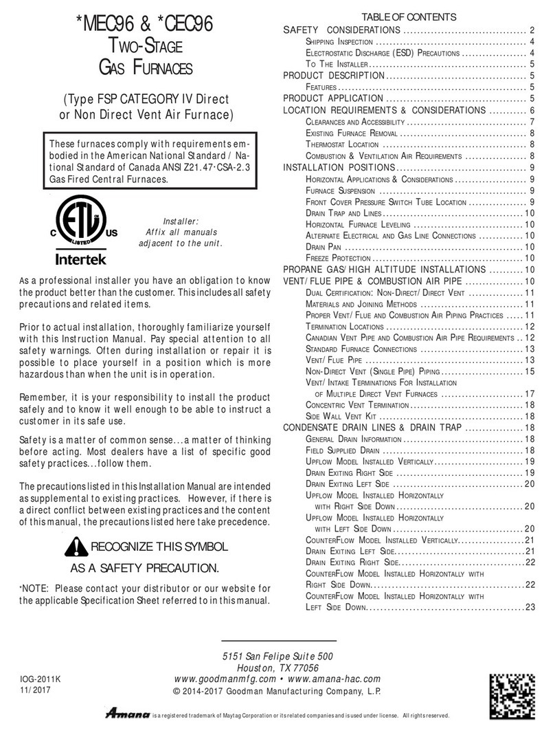
Amana Forced Air Central Furnace Design Complies With Requirements
Embodied in The American National Standard / National Standard of Canada
Shown Below.
ANSI Z21.47CAN/CGA-2.3 Central Furnaces
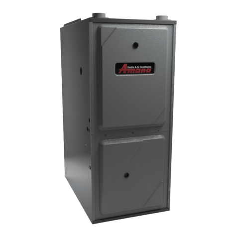
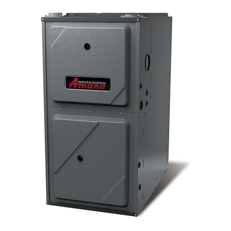
GUX-X, GUC-X, and GUD-X
Gas Fired Warm Air
Furnace
RECOGNIZE THIS SYMBOL AS A SAFETY PRECAUTION
Installation Instructions
Affix this manual, Specification Sheet and Users
Information Manual adjacent to the furnace.
Contents
To The Owner................................................................................. 2
To The Installer ............................................................................... 2
I. Safety and Unit Location ............................................................ 3
II. General Information ................................................................... 4
III. Air Requirements ....................................................................... 6
IV. Vent Pipe (All Models) and Combustion Air Pipe
(GUD Models) Materials .......................................................... 8
V. Vent Piping - GUX (All Installations),
GUC (All Installations), and GUD (One Pipe Installations) .... 9
VI. Combustion Air And Vent Piping (GUD - Two Pipe) ............. 11
VII. Condensate Piping ..................................................................15
VIII. Gas Piping ..............................................................................16
lX. Electrical Wiring .......................................................................20
X. Circulating Air and Filters........................................................23
XI. Sequence of Operation ............................................................24
XII. Start-Up and Adjustment ........................................................25
XIII. Maintenance ...........................................................................29
XlV. Functional Parts List ..............................................................32
10318715
2
WARNING
Should overheating occur or the gas
supply fail to shut off, turn off the man-
ual gas control valve to the furnace be-
fore shutting off the electrical supply.
To The Owner
It is important that you fill out the owners registration
card and mail it today. This will assist Amana in con-
tacting you should any service or warranty information
change in the future. When filling in the registration
card, be sure to include the Model, Manufacturing and
Serial Numbers, plus the installation date.
Your warranty certificate is also supplied with the unit.
Read the warranty carefully and note what is covered.
Keep the warranty certificate in a safe place, so you
can find it, if necessary.
If additional operating instructions are required, call
the dealer where the purchase was made.
To The Installer
Before installing this unit, please read this manual to
familiarize yourself on the specific items which must
be adhered to, such as maximum external static pres-
sure to unit, BTU input rating, air temperature rise,
minimum or maximum CFM, and motor speed connec-
tions.
KK
KK
Keeee
eeee
eepthis literp this liter
p this literp this liter
p this liter aa
aa
aturtur
turtur
tur ein a safe in a saf
e in a safe in a saf
e in a saf e place fe place f
e place fe place f
e place f or fu-or fu-
or fu-or fu-
or fu-
turtur
turtur
tur ere r
erer
er efef
efef
ef erer
erer
er enceence
enceence
ence ..
..
.
WARNING
If the information in these instructions
is not followed exactly, a fire or explo-
sion may result causing property dam-
age, personal injury or loss of life.
Do not store or use gasoline or other
flammable vapors and liquids in the
vicinity of this or any other appliance.
What to do if you smell gas:
 Do not try to light any appliance.
 Do not touch any electrical switch;
do not use any phone in your build-
ing.
 Immediately call your gas supplier
from a neighbors phone. Follow the
gas suppliers instructions.
 If you cannot reach your gas sup-
plier, call the fire department.
Installation and service must be per-
formed by a qualified installer, ser-
vice agency or the gas supplier.
3
Safety
 When the furnace is heating, the temperature of
the return air entering the furnace must be be-
tween 55°F and 100°F.
 If the furnace is installed near an area which will be
frequently contaminated by permanent wave solu-
tions, chlorinated waxes or cleaners, chlorine based
swimming pool chemicals, water softening chemi-
cals, de-icing salts or chemicals, carbon tetrachlo-
ride, halogen type refrigerants, cleaning solutions
(such as perchloroethylene), printing inks, paint
removers, varnishes, hydrochloric acid, cements
and glues, antistatic fabric softeners for clothes
dryers, and masonry acid washing materials, the
furnace should be sealed from this area so that no
contaminated air can reach the furnace. The fur-
nace must still have an adequate supply of com-
bustion air, either from a nearby uncontaminated
room or from outdoors. For details, see AIR RE-
QUIREMENTS Section III.
 Provisions must be made for intake of combustion
air (GUD) and venting combustion products out-
doors through proper venting systems. The length
of combustion air pipe (GUD) and flue pipe could
be a limiting factor in locating the furnace. See
Sections III and IV.
 Allow clearances from the enclosure as shown on
Specification sheet for fire protection, proper op-
eration, and service access. These clearances must
be permanently maintained. The combustion and
ventilating air openings in the front and top panels
of the furnace must never be obstructed.
 When the furnace is used in connection with a
cooling unit, the furnace must be upstream of, or in
parallel with, the cooling unit. For details see Sec-
tion VlI.
 This furnace produces condensate as it operates.
Do not locate the furnace or its condensate drain-
age system in an area subjected to below freezing
temperatures.
I. Safety and Unit Location
WARNING
To prevent personal injury or death due
to improper installation, adjustment, al-
teration, service or maintenance, refer
to this manual or for additional assis-
tance or information consult a qualified
installer, service agency or the gas sup-
plier.
WARNING
This product contains or produces a
chemical or chemicals which may cause
serious illness or death and which are
known to the State of California to cause
cancer, birth defects or other reproduc-
tive harm.
WARNING
To prevent possible death, personal in-
jury or equipment damage due to fire,
the following points must be observed
when installing the unit.
WARNING
To prevent possible death, personal in-
jury or property damage due to electri-
cal shock, the furnace must be located
to protect the electrical components
from water.
CAUTION
This unit must not be used as a
construction heater during the finish-
ing phases of construction on a new
structure. This type of use may result in
premature failure of the unit due to ex-
tremely low return air temperatures and
exposure to corrosive or very dirty at-
mospheres.
4
Location
 The furnace should be as centralized as is practical
with respect to the air distribution system.
 The furnace must be set on a level floor to enable
the condensate produced to drain properly. If the
floor may become wet or damp at times, the fur-
nace should be supported above the floor on a
concrete base sized approximately 1-1/2 larger
than the base of the furnace.
 Do not install the furnace directly on carpeting, tile,
or combustible material other than wood flooring.
 Do not install the furnace where the combustion air
is exposed to the following substances: permanent
wave solutions, chlorinated waxes or cleaners, chlo-
rine based swimming pool chemicals, water soften-
ing chemicals, de-icing salts or chemicals, carbon
tetrachloride, halogen type refrigerants, cleaning
solutions (such as perchloroethylene), printing inks,
paint removers, varnishes, hydrochloric acid, ce-
ments and glues, antistatic fabric softeners for
clothes dryers, and masonry acid washing materi-
als.
 Exposure to contaminated combustion air will result
in safety and performance related problems.
 When installed in a residential garage, the furnace
must be positioned so the burners and ignition source
are located not less than 18 inches (457 mm) above
the floor and protected from physical damage by
vehicles.
II. General Information
WARNING
Possible death, personal injury or prop-
erty damage due to fire, explosion,
smoke, soot, condensation, electrical
shock or carbon monoxide may result
from improper installation, repair, opera-
tion, or maintenance on this product.
WARNING
To prevent death, personal injury or prop-
erty damage due to fire, do not install
this furnace in a mobile home, trailer, or
recreational vehicle.
To ensure this upflow furnace operates safely and effi-
ciently, it must be installed, operated and maintained in
accordance with these installation and operating in-
structions, all local building codes and ordinances, or, in
their absence, with the latest edition of the National
Fuel Gas Code, ANSI Z223.1*, and/or CAN/CGA B149
Installation Codes, local plumbing or waste water codes
and other applicable local codes.
The rated heating capacity of the furnace should be
greater than or equal to the total heat loss of the area to
be heated. The total heat loss should be calculated by
an approved method or in accordance with A.S.H.R.A.E.
Guide or Manual J-Load Calculations published by
the Air Conditioning Contractors of America.
*Obtain from: American National Standards Institute
1430 Broadway New York. NY 10018
Transportation Damage
All furnaces are securely packed in shipping containers
tested according to the International Safe Transit Asso-
ciation standards. The carton must be checked upon
arrivalforexternaldamage.Ifdamageisfound,arequest
for inspection by carrier’s agent must be made in writing
immediately.
The furnace must be carefully inspected on arrival for
damageandboltsorscrewswhichmayhavecomeloose
in transit. In the event of damage the consignee should:
1. Make a notation on delivery receipt of any visible
damage to shipment or container.
2. Notify carrier promptly and request an inspection.
3. With concealed damage, carrier must be notified as
soon as possible - preferably within five days.
5
4. File the claim with the following support documents
within a nine month statute of limitations.
 Original or certified copy of the Bill of Lading, or
indemnity bond:
 Original paid freight bill or indemnity in lieu thereof
 Original or certified copy of the invoice, showing
trade and other discounts or reductions
 Copy of the inspection report issued by carriers
representative at the time damage is reported to
carrier.
The carrier is responsible for making prompt inspection
of damage and for a thorough investigation of each
claim. The distributor or manufacturer will not accept
claims from dealers for transportation damage.
Removal of Existing Furnace
When an existing furnace is removed from a venting
system serving other appliances, the venting system
may be too large to properly vent the remaining at-
tached appliances.
The following steps shall be followed with each appli-
ance remaining connected to the common venting sys-
tem placed in operation, while the other appliances
remaining connected to the common venting system
are not in operation.
(a) Seal any unused openings in the common venting
system.
(b) Visually inspect the venting system for proper size
and horizontal pitch and determine there is no block-
age or restriction, leakage, corrosion and other defi-
ciencies which could cause an unsafe condition.
(c) Insofar as is practical, close all building doors and
windows and all doors between the space in which
the appliances remaining connected to the com-
mon venting system are located and other spaces
of the building. Turn on clothes dryers and any
appliance not connected to the common venting
system. Turn on any exhaust fans, such as range
hoods and bathroom exhausts, so they will operate
at maximum speed. Do not operate a summer ex-
haust fan. Close fireplace dampers.
(d) Follow the lighting instructions. Place the appli-
ance being inspected in operation. Adjust thermo-
stat so appliance will operate continuously.
(e) Test for spillage at the draft hood relief opening
after 5 minutes of main burner operation. Use the
flame of a match or candle, or smoke from a ciga-
rette, cigar, or pipe.
(f) After it has been determined that each appliance
remaining connected to the common venting sys-
tem properly vents when tested as outlined above,
return doors, windows, exhaust fans, fireplace damp-
ers and any other gas burning appliance to their
previous conditions of use.
(g) If improper venting is observed during any of the
above tests, the common venting system must be
corrected in accordance with the latest edition of
the National Fuel Gas Code, ANSI Z223 1.
If resizing any portion of the common venting system,
use the appropriate table in Appendix G in the latest
edition of the National Fuel Gas Code, ANSI Z223.1.
Thermostat Location
In an area having good air circulation, locate the ther-
mostat about 5 feet high on a vibration-free inside wall,
Do not install the thermostat where it may be affected
by:
 drafts or dead spots behind door, in corners or
under cabinets.
 hot or cold air from ducts.
 radiant heat from sun or appliances.
 concealed pipes and chimneys.
 unheated (uncooled) areas behind the thermostat,
such as an outside wall.
Consult the instructions packaged with the thermostat
for mounting instructions.
6
III. Air Requirements
WARNING
Possible death, personal injury or prop-
erty damage may occur if the furnace
and other fuel-burning appliances are
not provided with enough fresh air for
proper combustion and ventilation of flue
gases. Most homes require outside air
to be supplied into the furnace area.
Improved construction and additional insulation in build-
ings has reduced the heat loss, making these buildings
much tighter around doors and windows so air infiltra-
tion is minimal. This creates a problem supplying com-
bustion and ventilation air for gas fired and other fuel
burning appliances. Use of appliances pulling air out of
the house (clothes dryers, exhaust fans, fireplaces,
etc.) increases this problem causing appliances to starve
for air.
Air Requirements
Most homes will require outside air be supplied to the
furnace area by means of ventilation grilles or ducts
connecting directly to the outdoors or spaces open to
the outdoors such as attics or crawl spaces. The follow-
ing information on air for combustion and ventilation is
reproduced from the National Fuel Gas Code NFPA54/
ANSI Z223.1 Section 5.3.
5.3.1 General:
(a) The provisions of 5.3 apply to gas utilization equip-
ment installed in buildings and which require air for
combustion, ventilation and dilution of flue gases from
within the building. They do not apply to (1) direct vent
equipment which is constructed and installed so that all
air combustion is obtained from the outside atmosphere
and all flue gases are discharged to the outside atmo-
sphere, or (2) enclosed furnaces which incorporate an
integral total enclosure and use only outside air for
combustion and dilution of flue gases.
(b) Equipment shall be installed in a location in which
the facilities for ventilation permit satisfactory combus-
tion of gas, proper venting and the maintenance of
ambient temperature at safe limits under normal condi-
tions of use. Equipment shall be located so as not to
interfere with proper circulation of air. When normal
infiltration does not provide the necessary air, outside
air shall be introduced.
(c) In addition to air needed for combustion, process air
shall be provided as required for: cooling of equipment
or material, controlling dew point, heating, drying, oxi-
dation or dilution, safety exhaust, odor control, and air
for compressors.
(d) In addition to air needed for combustion, air shall be
supplied for ventilation, including all air required for
comfort and proper working conditions for personnel.
(e) While all forms of building construction cannot be
covered in detail, air for combustion, ventilation and
dilution of flue gases for gas utilization equipment vented
by natural draft normally may be obtained by applica-
tion of one of the methods covered in 5.3.3 and 5.3.4.
(f) Air requirements for the operation of exhaust fans,
kitchen ventilation systems, clothes dryers, and fire-
places shall be considered in determining the adequacy
of a space to provide combustion air requirements.
5.3.2 Equipment Located in Unconfined Spaces: In
unconfined spaces (see definition below) in buildings,
infiltration may be adequate to provide air for combus-
tion ventilation and dilution of flue gases. However, in
buildings of tight construction (for example, weather
stripping, heavily insulated, caulked, vapor barrier, etc.),
additional air may need to be provided using the meth-
ods described in 5.3.3-b or 5.3.4.
Space, Unconfined. For purposes of this Code, a space
whose volume is not less than 50 cubic feet per 1,000
BTU per hour of the aggregate input rating of all appli-
ances installed in that space. Rooms communicating
directly with the space in which the appliances are
installed through openings not furnished with doors, are
considered a part of the unconfined space.
5.3.3 Equipment Located in Confined Spaces: (a)
All Air from Inside the Building: The confined space
shall be provided with two permanent openings
communicating directly with an additional room(s) of
sufficient volume so that the combined volume of all
spaces meets the criteria for an unconfined space. The
total input of all gas utilization equipment installed in
the combined space shall be considered in making this
determination. Each opening shall have a minimum
free area of 1 square inch per 1,000 BTU per hour of the
total input rating of all gas utilization equipment in the
confined space, but not less than 100 square inches.
One opening shall be within 12 inches of the top and
one within 12 inches of the bottom of the enclosure.
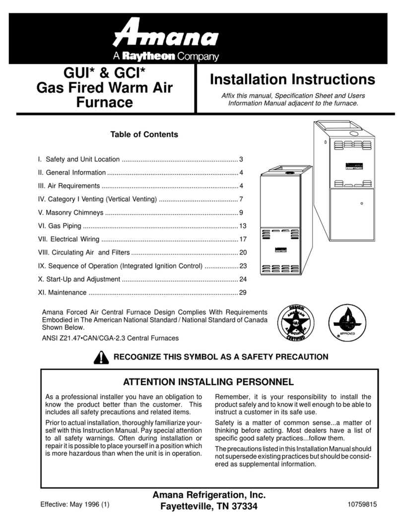
(See Figure 1 ) .
Figure 1
Equipment Located in Confined Spaces;
All Air from Inside Building. See 5.3.3-a
.
7
(b) All Air from Outdoors: The confined space shall be
provided with two permanent openings, one commenc-
ing within 12 inches of the top and one commencing
within 12 inches of the bottom of the enclosure. The
openings shall communicate directly, or by ducts, with
the outdoors or spaces (crawl or attic) that freely com-
municate with the outdoors.
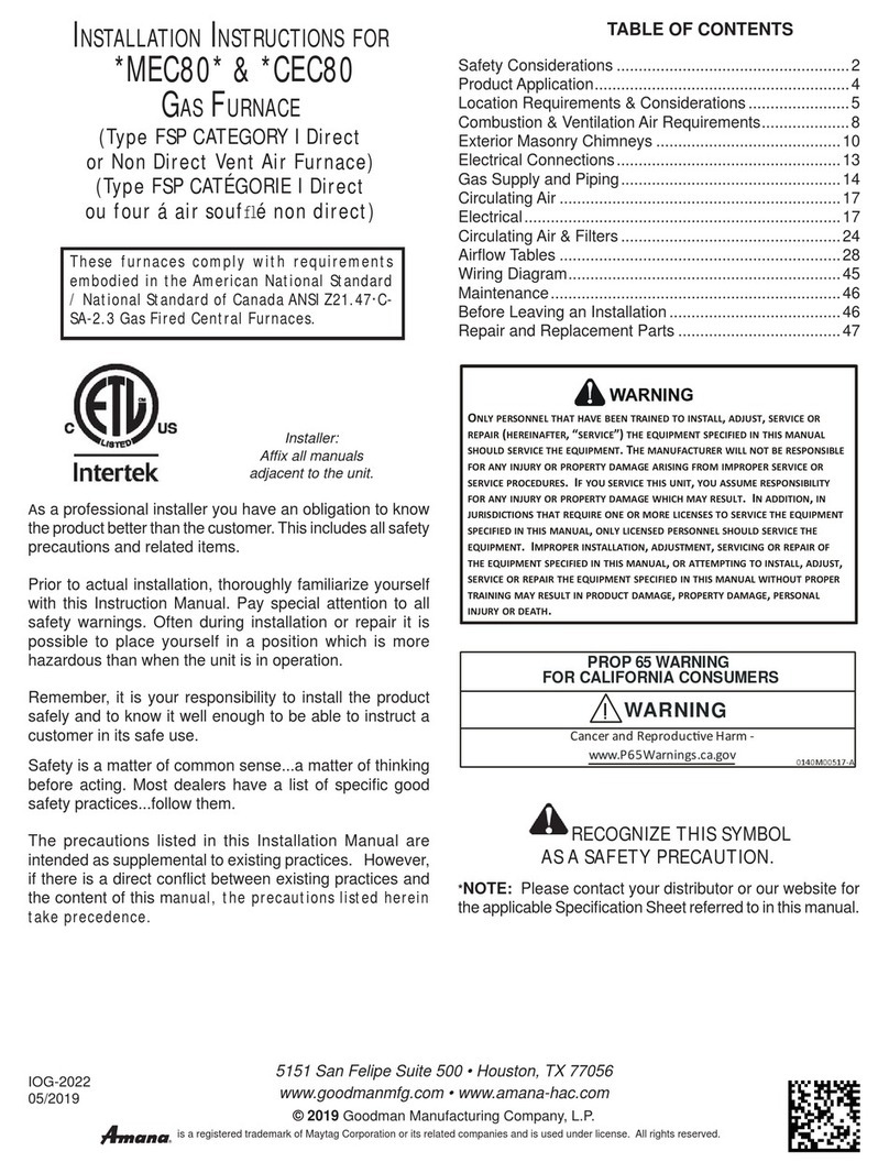
1. When directly communicating with the outdoors,
each opening shall have a minimum free area of 1
square inch per 4,000 BTU per hour of total input
rating of all equipment in the enclosure. (See Fig-
ure 2)
Figure 2
Equipment Located in Confined Spaces;
All Air from OutdoorsInlet Air from
Ventilated Crawl Space and Outlet Air to
Ventilated Attic. See 5.3.3-b
2. When communicating with the outdoors through
vertical ducts, each opening shall have a minimum
free area of 1 square inch per 4,000 BTU per hour
of total input rating of all equipment in the enclo-
sure. (See Figure 3.)
Figure 3
Equipment Located in Confined Spaces;
All Air from Outdoors Through Ventilated
Attic. See 5.3.3-b.
3. When communicating with the outdoors through
horizontal ducts, each opening shall have a mini-
mum free area of 1 square inch per 2,000 BTU per
hour of total input rating of all equipment in the
enclosure. (See Figure 4)
*If the appliance room is located against an outside wall and the air openings communicate
directly with the outdoors, each opening shall have a free area of not less than one square
inch per 4,000 BTU per hour of the total input rating of all appliances in the enclosure.
Figure 4
Equipment Located in Confined Spaces;
All Air from Outdoors. See 5.3.3-b.
4. When ducts are used, they shall be of the same
cross-sectional area as the free area of the open-
ings to which they connect. The minimum dimen-
sion of rectangular air ducts shall not be less than 3
inches.
8
IV. Vent Pipe (All Models) And
Combustion Air Pipe (GUD Models)
Materials
WARNING
Failure to follow these instructions can
result in bodily injury or death from as-
phyxiation. Therefore, carefully read and
follow all instructions given in this sec-
tion.
In order to achieve high efficiency, the products of
combustion from this furnace are cooled to the point
where condensation takes place. Consequently, the vent-
ing must be done in a different manner and with differ-
ent materials than with a conventional system. Two or
three inch PVC Schedule 40 pipe meeting ASTM D1785,
PVC primer meeting ASTM F656 and PVC solvent
cement meeting ASTM D2564 specifications must be
used. Only DWV type fittings meeting ASTM D2665
and ASTM D3311 can be used. Carefully follow the
manufacturers instructions in cutting, cleaning, and sol-
vent cementing of PVC or ABS pipe.
As an alternate to PVC pipe, primer, solvent cement,
and fittings; ABS materials which are in compliance
with the following specifications may be used: two or
three inch ABS Schedule 40 pipe must meet ASTM
D1527 and, if used in Canada, must be CSA listed.
Solvent cement for ABS to ABS joints must meet ASTM
D2235 and, if used in Canada, must be CSA listed. The
solvent cement used for the PVC to ABS transition joint
must meet ASTM D3138. Fittings must be DWV type
fittings which meet ASTM D2661 and ASTM D3311
and, if used in Canada, must be CSA listed. Carefully
follow the manufacturers instructions in cutting, clean-
ing, and solvent cementing PVC or ABS pipes.
WARNING
Solvent cements are combustible liquids
and should be kept away from all igni-
tion sources. (i.e. sparks, open flames
and excessive heat). Avoid breathing ce-
ment vapors or contact with skin and
eyes.
5.3.4 Specially Engineered Installations:
The requirements of 5.3.3 shall not necessarily govern
when special engineering, approved by the authority
having jurisdiction, provides an adequate supply of air
for combustion, ventilation, and dilution of flue gases.
5.3.5 Louvers and Grilles:
In calculating free area in 5.3.3, consideration shall be
given to the blocking effect of louvers, grilles or screens
protecting openings. Screens used shall not be smaller
than 1/4 inch mesh. If the area through a design of
louver or grille is known, it should be used in calculating
the size of opening required to provide the free area
specified. If the design and free area is not known, it
may be assumed that wood louvers will have 20-25
percent free area and metal louvers and grilles will have
60-75 percent free area. Louvers and grilles shall be
fixed in the open position or interlocked with the equip-
ment so that they are opened automatically during
equipment operation.
5.3.6 Special Conditions Created by Mechanical Ex-
hausting or Fireplaces:
Operation of exhaust fans, ventilation systems, clothes
dryers, or fireplaces may create conditions requiring
special attention to avoid unsatisfactory operation of
installed gas utilization equipment.
9
All 90 degree elbows must be medium (1/4 bend DWV)
or long radius (long sweep 1/4 bend DWV) types con-
forming to ASTM D3311. A medium radius (1/4 bend)
elbow is 3-1/16 inch minimum from the plane of one
opening to the centerline of the other opening for 2 inch
pipe (4-9/16 inch for 3 inch pipe).
This furnace must not be connected to any type B, BW,
or L vent or vent connector and must not be vented into
any portion of a factory built or masonry chimney,
except when used as a pathway for PVC pipe as de-
scribed below
Flexible couplings for joining PVC pipe (sometimes
called no hub connectors) have been used by some
installers to connect the field supplied portion of the
vent system to the furnace. Amana Refrigeration, Inc.
does not encourage nor recommend using these con-
nectors. However, if you do choose to use no-hub
connectors, the connectors must be gas tight, water
tight, and able to withstand continuous exposure to the
warm, moist, acidic flue products of the furnace.
It is the responsibility of the installer to follow the manu-
facturers recommendations and to verify that all flue
pipe connectors used are compatible with the furnace
flue products. In addition the connectors must possess
adequate structural integrity to prevent flue pipe sepa-
rations during furnace operation.
V. Vent Piping - GUX (All
Installations), GUC (All Installations),
and GUD (One Pipe Installations)
IMPORTANT: The length of the vent pipe affects the
performance of the furnace and therefore must be care-
fully sized.
Pipe Diameter for GUC (All Models), GUX (All Models)
and GUD045 (One Pipe) Venting
# of Inside
Elbows
5 to
10 feet
10 to
15 feet
15 to
20 feet
20 to
25 feet
25 to
30 feet
30 to
35 feet
35 to
40 feet
1 2"2" 2" 2"2"2" 2"
2 2"2" 2" 2"2"2" 2"
3 2"2" 2" 2"2"2" 3"
4 2"2" 2" 2"2"3" 3"
Pipe Diameter for GUD070, GUD090 and GUD115
(One Pipe) Venting
# of Inside
Elbows
5 to
10 feet
10 to
15 feet
15 to
20 feet
20 to
25 feet
25 to
30 feet
30 to
35 feet
35 to
40 feet
1 3"3" 3" 3"3"3" 3"
2 3"3" 3" 3"3"3" 3"
3 3"3" 3" 3"3"3" 3"
4 3"3" 3" 3"3"3" 3"
The inside feet of straight pipe and inside elbows repre-
sent the venting system from the furnace to the inside
wall. Follow termination instructions for going from the
inside wall to the outside in the next paragraph.
When the vent pipe goes through an outside wall, the
vent must terminate at least one foot outside to keep
moist combustion products away from the structure.
The vent termination must be at least three feet above
any forced air inlet located within ten feet. It must be at
least four feet below, four feet horizontally from or one
foot above any door, window, or gravity air inlet into any
building. The vent must terminate at least one foot
above ground level. If heavy snow is expected locally,
this distance may need to be increased. The vent shall
not terminate over public walkways, or over an area
where condensate or vapor could create a nuisance or
hazard or could be detrimental to the operation of regu-
lators, relief valves, or other equipment. Drill a 2-3/8
inch diameter hole through the wall for 2 inch pipe. (For
3 inch pipe, drill a 3-1/2 inch diameter hole.) Cut a piece
of PVC (ABS) pipe that is the thickness of the wall plus
the depth of the sockets of the fittings to be installed on
the inside and outside of the walls. To prevent the vent
pipe from moving and possibly damaging connections,
locate the fitting on the inside wall and a coupling on the
outside wall as shown in Fig. 5. To prevent condensate
from freezing inside the PVC flue pipe in extremely cold
conditions or in long outdoor runs, insulation may be
required on the cut side of the PVC pipe. Use 1/2 inch
thickness closed cell foam insulation such as Armaflex
or Insultube.
10
Additional Canadian Venting
Requirements
In Canada venting shall conform to the requirements
of the current CANI-B149 Installation Codes.
Use only C.S.A. Listed 2 inch or 3 inch nominal diam-
eter PVC or ABS pipe and fittings throughout.
The Minimum vent consists of 3 feet of straight pipe
with 2 elbows (9 equivalent feet).
A single wall vent shall not be run vertically through
the roof. The vent may be run through an existing
unused chimney as described in the previous venting
section provided the space between the vent pipe and
the chimney is insulated and closed with a weather
tight, corrosion resistant flashing.
Cut all vent pipe at right angles. Remove inside and
outside burr at each cut. Use cleaner to clean pipe
and fitting socket. Use CSA listed cement to fasten
pipe and fittings.
Follow manufacturers cleaning and cementing instruc-
tions carefully to avoid leakage.
NOTE: ALL PIPING EXPOSED OUTDOORS OR IN
UNHEATED AREAS MUST BE INSULATED WITH
1/2 inch THICK CLOSED CELL FOAM INSULATION
SUCH AS ARMAFLEX OR INSULTUBE.
The vent terminal shall not be located:
1. Less than 12 inches above the finished grade line.
2. Less than 36 inches from any building opening or
any gas service regulator. (For gas service regula-
tors in the Province of Ontario, 72 inches.)
3. Less than 72 inches from the combustion air inlet of
another appliance.
4. Directly above a gas utility meter or service regula-
tor.
5. Over a walkway unless 84 inches above grade.
Figure 5
Horizontal Vent Termination
In a basement installation, the vent pipe may be run
between the joist spaces. If the vent must go below the
joists, then the pipe must run up into the last joist space
to go through the header. Two 45° elbows should be
used rather than 90s. The horizontal run must not have
any sag that can hold condensate and should pitch up at
least 1/4 inch per foot so that condensate will run back
to the unit to drain. Support the horizontal run at least
every three feet. Allow for some expansion and con-
traction from temperature fluctuations. The normal di-
rection changes usually account for this, but if you have
a long run followed by a short offset of less than 40
inches such as going up into the last joist space, the
pipe should be tightly clamped to prevent flex loading
on the fittings. Seal around the pipe on the outside wall
with silicone caulking material.
If the vent is to be run vertically through the roof, it must
extend at least 12 inches above the roof line and shall
be at least 12 inches from any vertical wall. It must
terminate at least three feet above any forced air inlet
located within 10 feet, and at least 12 inches from any
door, window, or gravity air inlet into any building. If
heavy snow is expected to remain on the roof, the
clearances to vertical walls and the roof may need to be
increased. The vent must be made tight where it pen-
etrates the roof with a proper flashing such as used with
a plastic plumbing vent. The vent may be run through
an existing unused chimney: however, the pipe must
be used all the way through to at least 12 inches above
the top of the existing chimney. The space between the
vent pipe and the chimney must be closed with a weather
tight, corrosion resistant flashing. Never vent with an
existing appliance or vent used by a solid fuel appliance.
WARNING
Upon completion of the furnace installa-
tion, carefully inspect the entire flue sys-
tem both inside and outside the furnace
to assure it is properly sealed. Leaks in
the flue system can result in serious per-
sonal injury or death due to exposure to
flue products, including carbon monox-
ide.