manuals.online logo
Brands
  1. Home
  2. •
  3. Brands
  4. •
  5. Amana
  6. •
  7. Furnace
  8. •
  9. Amana LPM-10 User manual

Amana LPM-10 User manual

Other Amana Furnace manuals
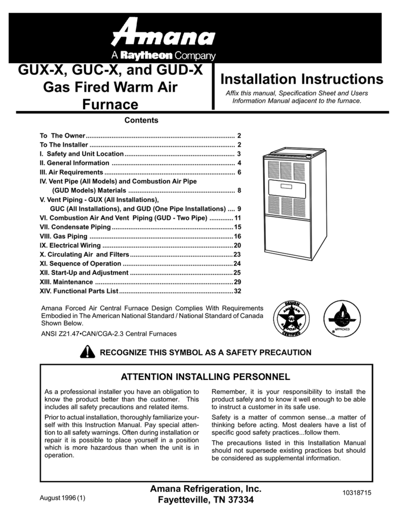
Amana AMH95 Series User manual

Amana

Amana AMH95 Series User manual

Amana CVC96 BB Series User manual

Amana

Amana CVC96 BB Series User manual

Amana M9C96 Series User manual

Amana

Amana M9C96 Series User manual

Amana M8 User manual

Amana

Amana M8 User manual

Amana AMS95 User manual

Amana

Amana AMS95 User manual

Amana GUI User manual

Amana

Amana GUI User manual

Amana ACVC96 User manual

Amana

Amana ACVC96 User manual

Amana GUI User manual

Amana

Amana GUI User manual

Amana MVM97 Series User manual

Amana

Amana MVM97 Series User manual

Amana GUIA Series Operating instructions

Amana

Amana GUIA Series Operating instructions

Amana AMVS96-U User manual

Amana

Amana AMVS96-U User manual

Amana MVC80 User manual

Amana

Amana MVC80 User manual

Amana AM9S80 User manual

Amana

Amana AM9S80 User manual
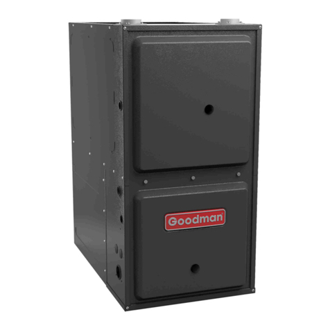
Amana *MEC96 User manual

Amana

Amana *MEC96 User manual

Amana AMVC8 Series User manual

Amana

Amana AMVC8 Series User manual

Amana GUIS User manual

Amana

Amana GUIS User manual

Amana AMH95 Series User manual

Amana

Amana AMH95 Series User manual

Amana AMS9 User manual

Amana

Amana AMS9 User manual

Amana MES80 User manual

Amana

Amana MES80 User manual

Amana *CVC96 User manual

Amana

Amana *CVC96 User manual
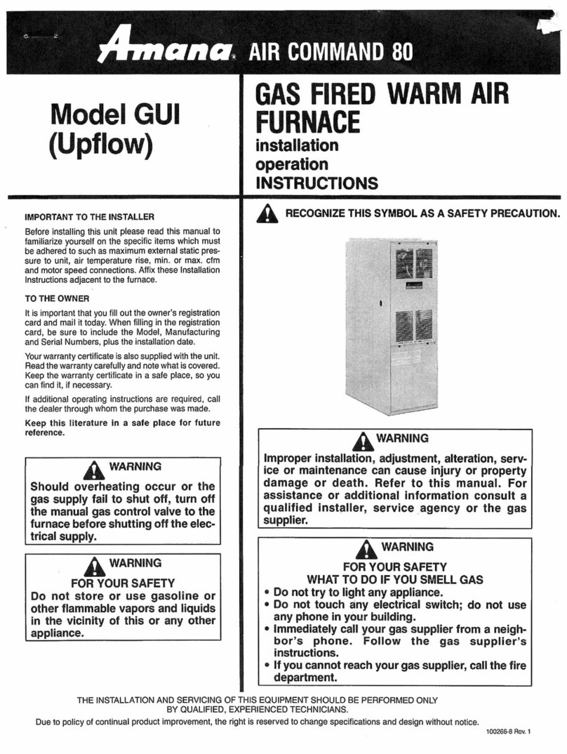
Amana GULA Guide

Amana

Amana GULA Guide

Amana AMV9 User manual

Amana

Amana AMV9 User manual

Amana GUX-X User manual

Amana

Amana GUX-X User manual

Amana GMES80 Operating instructions

Amana

Amana GMES80 Operating instructions

Popular Furnace manuals by other brands

Unitary products group AHV8 UH installation manual

Unitary products group

Unitary products group AHV8 UH installation manual

VERDER CARBOLITE GERO RHF 14/8 Installation, operation and maintenance instructions

VERDER

VERDER CARBOLITE GERO RHF 14/8 Installation, operation and maintenance instructions

Tempstar B Series Service and technical support manual

Tempstar

Tempstar B Series Service and technical support manual

Carrier Performance 59SP5A Installation, start-up, operating and service and maintenance instructions

Carrier

Carrier Performance 59SP5A Installation, start-up, operating and service and maintenance instructions

Armstrong EG7H SERIES Installation and maintenance instructions

Armstrong

Armstrong EG7H SERIES Installation and maintenance instructions

Payne PG92ESA Installation, start-up, operating and service and maintenance instructions

Payne

Payne PG92ESA Installation, start-up, operating and service and maintenance instructions

NANOE Zetasinter Operation manual

NANOE

NANOE Zetasinter Operation manual

SUPREME FEM10-M2301CM-A Installation instructions and homeowner's manual

SUPREME

SUPREME FEM10-M2301CM-A Installation instructions and homeowner's manual

Johnson Controls TM9T User's information manual

Johnson Controls

Johnson Controls TM9T User's information manual

Fluke 9118A user manual

Fluke

Fluke 9118A user manual

Lennox EL195UHE Elite Series Unit information

Lennox

Lennox EL195UHE Elite Series Unit information

Intertherm M7RL Series user manual

Intertherm

Intertherm M7RL Series user manual

HDG Pelletmaster 15 Operation manual

HDG

HDG Pelletmaster 15 Operation manual

Nortek MG2S Series installation instructions

Nortek

Nortek MG2S Series installation instructions

VERDER CARBOLITE GERO ABF 8/28 Installation, operation and maintenance instructions

VERDER

VERDER CARBOLITE GERO ABF 8/28 Installation, operation and maintenance instructions

Goodman GMV9 Installation & operating instructions

Goodman

Goodman GMV9 Installation & operating instructions

SUPREME SUP10-M2301C Installation instructions and homeowner's manual

SUPREME

SUPREME SUP10-M2301C Installation instructions and homeowner's manual

Dettson AMT400B34-SM1PMA Installation instructions and homeowner's manual

Dettson

Dettson AMT400B34-SM1PMA Installation instructions and homeowner's manual

manuals.online logo
manuals.online logoBrands
  • About & Mission
  • Contact us
  • Privacy Policy
  • Terms and Conditions

Copyright 2025 Manuals.Online. All Rights Reserved.

1
LPM-10 CONVERSION KIT
34" MODULATING FURNACE
NATURAL GAS TO L.P. GAS CONVERSION KIT FOR
FURNACES EQUIPPED WITH WHITE-RODGERS 36J27 SERIES GAS VALVES
Goodman Manufacturing Company, L.P.
5151 San Felipe, Suite 500 • Houston, TX 77056
©2018 Goodman Manufacturing Company, L.P.
is a registered trademark of Maytag Corporation or its related companies and is used under license
to Goodman Company, L.P., Houston, TX, USA. All rights reserved.
IOG-7004
November 2018
DO NOT DISCARD - RETAIN THESE INSTRUCTIONS FOR FUTURE USE
APPLICATION
This modulating Natural Gas to modulated L.P. Gas Conversion kit
allows the 36J27 Series gas valves to be used on L.P. applications.
THIS CONVERSION KIT IS FOR USE WITH WHITE-RODGERS 36J27
SERIES GAS VALVES ONLY. Tools required for the conversion are
listed below.
.093 SOCKET HEAD
SCREW OUTLET
PRESSURE TAP
(SOME MODELS)
1/8 - NPT
OUTLET
PRESSURE
TAP
L.P. LABEL (SUPPLIED WITH KIT)
JUMPER (SUPPLIED WITH KIT)
ON/OFF SWITCH
A
CCESS PLUG - (PRESSURE FINE ADJUSTMENT)
SCREW IS LOCATED BENEATH PLUG)
Figure 1 - 36J27 Modulating Gas Valve
Q'ty Description
1 Needle-Nose Pliers
17/16"BoxWrench
11/4"NutDriver
1 1/8" Flat Blade Screwdriver
1Manometer to read inlet and outlet pressure of the
gas valve (minimum range: 0"- 20" W.C.)
Gas leak detection solution like a soap and water
solution. Always wipe the solution from the joints
when testing is completed.
Required Tools for Conversion Kit
Only personnel that have been trained to install, adjust, service
or repair (hereinafter, “service”) the equipment specified in
this manual should service the equipment. The manufacturer
will not be responsible for any injury or property damage
arising from improper service or service procedures. If you
service this unit, you assume responsibility for any injury or
property damage which may result. In addition, in jurisdictions
that require one or more licenses to service the equipment
specified in this manual, only licensed personnel should service
the equipment. Improper installation, adjustment, servicing
or repair of the equipment specified in this manual, or
attempting to install, adjust, service or repair the equipment
specified in this manual without proper training may result in
product damage, property damage, personal injury or death.
Cancer and Reproductive Harm -
www.P65Warnings.ca.gov
PROP 65 WARNING
FOR CALIFORNIA CONSUMERS
0140M00513-A
2
TO CONVERT FROM NATURAL TO L.P. GAS
1. Shut OFF gas supply at manual shutoff and turn OFF power to
the furnace.
2. Remove access door.
3. Disconnect wiring from the gas valve.
4. Remove the gas manifold assembly by removing the four
screws connecting it to the burner bracket.
See Figure 2 below.
Figure 2 - Gas Manifold Removal
5. Remove natural gas orifices from gas manifold using 7/16"
box end wrench.
6. Visually inspect L.P. gas orifices (B40899125) for damage and
drill size (marked on face with #125) before installation. In-
stall orifices and tighten with a box-end wrench, take care to
avoid crossthreading or over tightening.
7. Remove the “NAT. GAS” label from the top of the 36J27 gas
valve.
8. Use needle nose pliers to place the jumper (see enclosed F92-
1021 kit) on the receptacle. Make sure both pins engage the
jumper .
9. Place the “L.P.” label (see the enclosed F92-1021 kit) on the
gas valve, covering the jumper installed in step 8.
10. Attach the “WARNING” label (see the enclosed F92-1021 kit)
to the gas valve where it can readily be seen.
11. Attach the gas manifold assembly to the burner bracket using
the four screws removed in step 4.
L.P. GAS PRESSURE CHECK
L.P. Gas Supply Pressure must be verified with all L.P. appliances
in operating mode. See Table 1 for the required L.P. gas pressure.
1. Turn OFF electrical power & gas supply to the unit.
2. Use a 3/16" Allen wrench to remove the 1/8"inlet pressure tap
from the gas valve.
3. Connect a calibrated water manometer or appropriate gas
pressure gauge at the gas valve inlet pressure tap.
4. Turn ON the power and gas, put the unit into heating cycle on
high fire (100%). Tap plub. The pressure must be leak checked
after resealing.len
Minimum: 11" w.c. Maximum: 13" w.c.
Propane Gas Supply Pressure Range
MANIFOLD PRESSURE CHECK
See Table 2 for the required L.P. gas manifold pressure. The gas
valve outlet pressure is automatically adjusted for LP by installa-
tion of the jumper in step 8. Only minor changes to manifold
pressure should be made by adjusting the gas valve pressure
regulator. Minor adjustments may be made by removing the
access plug and turning the fine-adjustment screw with a 1/8"flat
blade screwdriver. Adjustment should only be done while moni-
toring outlet pressure with a suitable manometer properly at-
tached to the outlet pressure tap.
Propane Gas Manifold Pressure Range
Low Stage High Stage
2.3" - 2.7" w.c. 9.7" - 10.3" w.c.
1. Turn OFF electrical power & gas supply to the unit.
2. Use a 3/16"Allen wrench to remove the 1/8"outlet pressure
tap from the gas valve.
3. Connect a calibrated water manometer or appropriate gas
pressure gauge at the gas valve outlet pressure tap.
4. Turn ON the power and gas, put the unit into heating cycle on
high fire (100%).
5. Remove the White cap located on top the gas valve next to the
+ & - symbols.
6. Use a 1/8"flat blade screwdriver to turn the fine adjustment
screw; clockwise (+) to increase manifold pressure, counter-
clockwise (-) to decrease manifold pressure.
7. After adjustment is made, turn OFF gas to the unit at the manual
shutoff valve and disconnect manometer. Reinstall line pres-
sure tap plug. The pressure tap must be leak checked after
resealing.
3
THISPAGELEFTINTENTIONALLYBLANK
4
NOTE: SPECIFICATIONS AND PERFORMANCE DATA LISTED HEREIN ARE SUBJECT TO CHANGE WITHOUT NOTICE
©2018 Goodman Manufacturing Company, L.P.
• Products
• Warranties
• Customer Services
Quality Makes the Difference!
All of our systems are designed and manufactured with the same high quality standards regardless of size or effi-
ciency. We have designed these units to significantly reduce the most frequent causes of product failure. They are
simple to service and forgiving to operate. We use quality materials and components. Finally, every unit is run tested
before it leaves the factory. That’s why we know. . .There’s No Better Quality.
Visit our website at www.goodmanmfg.com or www.amana-hac.com for information on:
• Parts
• Contractor Programs and Training
• Financing Options
CUSTOMER FEEDBACK
We are very interested in all product comments.
Please fill out the feedback form on one of the following links:
Goodman® Brand Products: (http://www.goodmanmfg.com/about/contact-us).
Amana® Brand Products: (http://www.amana-hac.com/about-us/contact-us).
You can also scan the QR code on the right for the product brand
you purchased to be directed to the feedback page.
GOODMAN® BRAND AMANA® BRAND