4
PRODUCT DESIGN 3. Conversionkits for high altitude natural orpropanegas
operation are available. See High Altitude Derate chart
fordetails.
4. Installer must supply the following gas line fittings, de-
pendingon which entrance isused:
Left -- Two 90º Elbows, one close nipple, straight pipe.
Right --Straight pipe toreach gas valve.
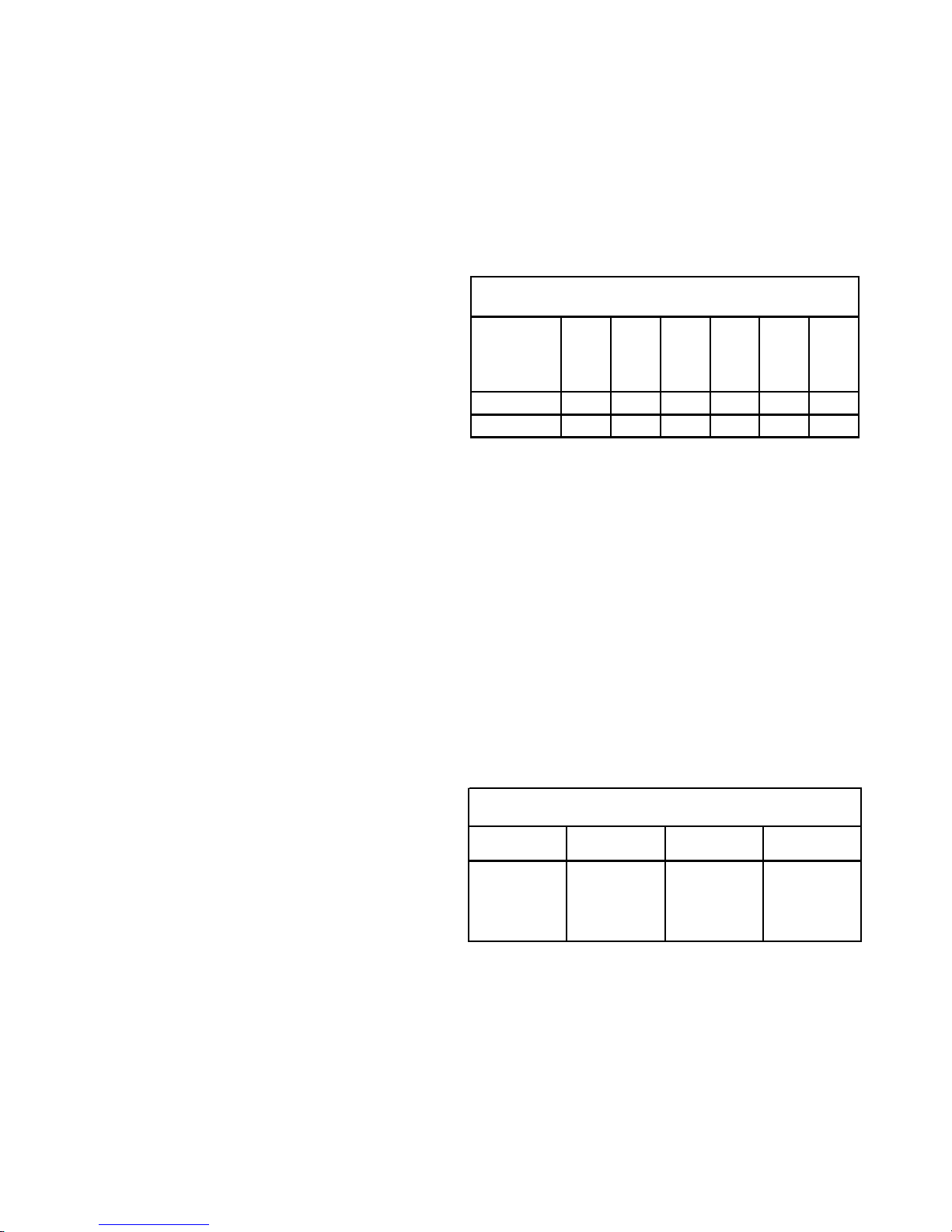
Accessibility Clearances (Minimum)
POSITION*
FRONT
SIDES
REAR
TOP
FLUE
FLOOR
Upflow30010C
Horizontal36060C
*= All positioning is determined as installed unit is viewed from the front.
C= If placed on combustible floor, floor MUST be wood only.
MINIMUM CLEARANCES TO COMBUSTIBLE MATERIALS
(INCHES)
NC= For instalaltion on non-combustible floors only. A non-combustible
subbase must be used for installations on combustible flooring.
24"at front isrequired for servicing orcleaning.
Note: Inall cases accessibility clearanceshall take prece-
denceoverclearancesfrom theenclosurewhere accessibil-
ityclearancesaregreater. Alldimensionsaregivenininches.
High Altitude Derate
Whenthis furnace is installedat high altitude, theappropri-
ate High Altitude orifice kit must be installed. This is re-
quireddue tothe natural reductionin thedensity of boththe
gas fuel and combustion air as altitude increases. The kit
will provide the proper design certified input rate within the
specifiedaltitude range.
0 to
7,000 ft. 7,001 to
9,000 ft. 9,001 to
11,000 ft. 7,001 to
11,000 ft.
LPM-05
LPM-06
2
Propane
Conversion Kit
rifi
HANG11
High Altitude
Natural Gas Kit
(#44 Orifices)
HANG12
High Altitude
Natural Gas Kit
(#45 Orifices)
HALP 10
High Altitude
LP Gas Kit
(#56 Orifices)
PROPANE AND HIGH ALTITUDE KITS
FOR *MH95*****XA* MODELS
1
LPM-05* supports White-Rodgers 2-stage valves only
2
LPM-06* supports Honeywell and White-Rodgers 2-stage valves
High altitude kits are purchased according to the installa-
tionaltitudeandusageofeithernaturalorpropanegas.Refer
tothe chartabove fora tabular listingof appropriatealtitude
rangesandcorrespondingmanufacturer’shighaltitudeNatu-
ralGas andPropane Gaskits. For atabular listingof appro-
priatealtituderangesandcorrespondingmanufacturer'sHigh
Altitude Pressure Switch kits, refer to either the Pressure
Switch Trip Points & Usage Chart in this manual or the Ac-
cessoryCharts in Service Instructions.
GeneralOperation
The*MH95furnacesare equippedwithanelectronic ignition
deviceused tolighttheburnersand aninduced draftblower
to exhaust combustion products.
Aninterlock switchpreventsfurnace operationif the blower
door is not in place. Keep the blower access door in place
exceptfor inspection andmaintenance.
This furnace is also equipped with a self-diagnosing elec-
tronic control module. In the event a furnace component is
notoperatingproperly, thecontrol moduleLED will flashon
and off in a factory-programmed sequence, depending on
theproblem encountered. Thislight can beviewed through
theobservation windowinthe bloweraccess door. Referto
theTroubleshooting Chartforfurther explanationof theLED
codesandAbnormal Operation-Integrated IgnitionControl
section in the Service Instructions for an explanation of the
possibleproblem.
Therated heatingcapacity of thefurnace shouldbe greater
thanor equal to thetotal heat loss of thearea to be heated.
The total heat loss should be calculated by an approved
methodor inaccordance with “ASHRAEGuide” or “Manual
J-LoadCalculations”published bytheAir ConditioningCon-
tractors of America.
*Obtain from: American National Standards Institute 1430
BroadwayNew York,NY 10018
LocationConsiderations
• The furnace should be as centralized as is practical
with respect to the air distribution system.
• Donot installthe furnacedirectlyon carpeting,tile, or
combustiblematerial otherthan wood flooring.
• When suspending the furnace from rafters or joists,
use 3/8" threaded rod and 2” x 2” x 3/8” angle as
shownintheInstallation andServiceInstructions.The
length of the rod will depend on the application and
clearancenecessary.
• When installed in a residential garage, the furnace
mustbepositioned sothe burnersandignition source
are located not less than 18 inches (457 mm) above
the floor and protected from physical damage by ve-
hicles.
Notes:
1. Installermustsupply oneortwoPVC pipes:onefor com-
bustionair(optional)andonefortheflueoutlet(required).
Ventpipe mustbe either2” or3” in diameter,depending
uponfurnace input,number ofelbows, lengthof runand
installation (1 or 2 pipes). The optional Combustion Air
Pipeisdependenton installation/coderequirementsand
must be 2” or 3” diameter PVC.
2. Linevoltagewiring canenterthrough therightor leftside
ofthe furnace.Low voltage wiringcan enterthrough the
rightor left side offurnace.