Amana Menumaster DEC11E2 Installation guide

Model Number List
2
DEC11E..........(P1325203M)
(P1330512M)
DEC11E2........(P1331213M)
(P1331235M)
DEC14E..........(P1325207M)
(P1330516M)
DEC14E2........(P1331217M)
(P1331239M)
DEC18E..........(P1325211M)
(P1330520M)
DEC18E2........(P1331221M)
(P1331243M)
HDC511..........(P1325201M)
(P1330510M)
HDC511A .......(P1325213M)
HDC5112........(P1331211M)
(P1331233M)
HDC514..........(P1325205M)
(P1330514M)
HDC514A .......(P1325214M)
HDC5142........(P1331215M)
(P1331237M)
HDC518..........(P1325209M)
(P1330518M)
HDC518A .......(P1325215M)
HDC5182........(P1331219M)
(P1331241M)
HDC5212........(P1331224M)
(P1331245M)
MCHDC521 ....(P1331246M)
(P1331225M)
UC11E............(P1325204M)
(P1330513M)
UC11E2..........(P1331214M)
(P1331236M)
UC14E............(P1325208M)
(P1330517M)
UC14E2..........(P1331214M)
(P1331240M)
UC18E............(P1325212M)
(P1330517M)
UC18E2..........(P1331222M)
(P1331244M)
UHDC511 .......(P1325202M)
(P1330511M)
UHDC5112 .....(P1331212M)
(P1331234M)
UHDC514 .......(P1325206M)
(P1330515M)
UHDC5142 .....(P1331216M)
(P1331238M)
UHDC518 .......(P1325210M)
(P1330519M)
UHDC5182 .....(P1331220M)
(P1331242M)
CDEC14E2.....(P1331251M)
CDEC18E2 (P1331252M)
CDEC21E2.....(P1331253M)
CHDC5142 (P1331248M)
CHDC5182 (P1331249M)
CHDC5212 (P1331250M)

3
Table of Contents
Model Number List...............................................................................................................2
Table of Contents.................................................................................................................3
Specifications.......................................................................................................................4
Quick Start Reference Guide...............................................................................................5
Inner Door/Window Removal...............................................................................................7
Technical Bulletin CR-236-B - Broken Tray........................................................................8
Air Flow.................................................................................................................................9
Improved Filter for .6 Compact Ovens..............................................................................10
Interlock Switches..............................................................................................................11
Switch Replacement / Door Adjustment...........................................................................12
Touch Panel and Control Board........................................................................................13
Disassembly ...............................................................................................................14 – 16
Component Specifications........................................................................................17 – 19
Power Testing Procedure..................................................................................................20
Isolation Test – Two Magnetron Models...........................................................................21
Wiring and Schematic Diagrams................................................................................22 - 25

4
CAUTION
!
All safety information must be followed as provided in Service Manual RS5320013.
!
WARNING
To avoid risk of electrical shock, personal injury or death; disconnect power to oven and discharge capacitor
before servicing, unless testing requires power.
Models
UHDC511*
UC11E*
HDC511*
HDC511A
DEC11E* UHDC514*
UC14E*
HDC514*
HDC514A
DEC14E*
CHDC514
CDEC14E2
UHDC518*
UC18E*
HDC518*
HDC518A
DEC18E*
CHDC518
CDEC18E2
Power Source
Voltage AC 230 VAC 230 VAC 230 VAC 230 VAC 230 VAC 230 VAC
Amperage (single unit) 13 A 13 A 13 A 13 A 13 A 13 A
Frequency 50 Hz 50 Hz 50 Hz 50 Hz 50 Hz 50 Hz
Single phase, 3 wire earthed X X X X X X
Power Output
Nominal microwave energy (IEC705) 1100 Watts 1100 Watts 1400 Watts 1400 Watts 1800 Watts 1800 Watts
Minimum temperature rise (∆T) 11º F / 5.5º C 11º F / 5.5º C 14º F / 7.5º C 14º F / 7.5º C 18º F / 10º C 18º F / 10º C
Operating frequency 2450 MHz 2450 MHz 2450 MHz 2450 MHz 2450 MHz 2450 MHz
Power Consumption
Cook condition microwave 1800 W / 8 A 1800 W / 8 A 2300 W / 10 A 2300 W / 10 A 3000 W / 13 A 3000 W / 13 A
Dimensions
Cabinet
Width 423 mm 423 mm 423 mm 423 mm 423 mm 423 mm
Height 335 mm 335 mm 335 mm 335 mm 335 mm 335 mm
Depth 548 mm 548 mm 578 mm 578 mm 578 mm 578 mm
Oven Interior
Width 331 mm 331 mm 331 mm 331 mm 331 mm 331 mm
Height 175 mm 175 mm 175 mm 175 mm 175 mm 175 mm
Depth 305 mm 305 mm 305 mm 305 mm 305 mm 305 mm
Weight
Crated 29 kg 29 kg 31 kg 31 kg 31 kg 31 kg
Models MCHDC521
DEC21E2
HDC5212
CHDC5212
CDEC21E2
Power Source
Voltage AC 230 VAC 230 VAC
Amperage (single unit) 16 A 32 A
Frequency 50 Hz 50 Hz
Single phase, 3 wire earthed X X
Power Output
Nominal microwave energy (IEC705) 2100 Watts 2100 Watts
Minimum temperature rise (∆T) 21º F / 11.5º C 21º F / 11.5º C
Operating frequency 2450 MHz 2450 MHz
Power Consumption
Cook condition microwave 3100 Watts / 13.5 A 3100 Watts / 13.5 A
Dimensions
Cabinet
Width 423 mm 423 mm
Height 335 mm 335 mm
Depth 578 mm 578 mm
Oven Interior
Width 331 mm 331 mm
Height 175 mm 175 mm
Depth 305 mm 305 mm
Weight
Crated 31 kg 31 kg

5

6

7
Inner Door/Window Removal
1. Open oven door.
2. Remove screws on hinge side.
3. Beginning at the bottom, carefully insert 1” putty knife between inner and outer door. Pry up on inner
door to release tabs, (2 tabs per side). Work in a clockwise direction to release all tabs, see illustration
below.
1
2
3
4
Tabs
Remove
screws
CAUTION
!
When glass retainer is removed, be careful glass does not fall out of frame.

8
Bulletin
Type Parts Manual Update
Policy Letter
√Service Information
Attention Service Managers
√Service and Parts Managers
Models CRC and HDC Compact Commercial Ovens
Issue Broken tray as a result of arcing at front lip of cavity.
Warranty Ceramic trays may be claimed under warranty only if damage was caused by
antenna failure (arcing).
Trays are not covered under warranty if there is evidence that damage was caused by impact,
thermal shock (frozen or refrigerated product placed on warm tray), oven operated with metal pans,
oven operated without a food load or lack of proper cleaning and maintenance.
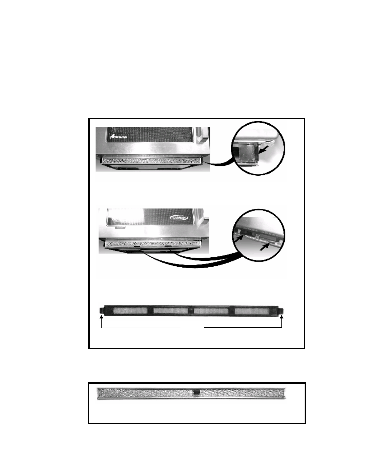
NOTE: Typical symptoms of metal pan usage or empty cavity operation include arc spots on the
front lip of cavity, 1 to 2 inches from either side.
Action If encountering arcing at front lip of cavity, proceed as follows:
1. Check antenna operation – if either antenna is stalled, hot spots will occur.
2. Remove oven tray.
3. Thoroughly remove any carbon build-up from front lip using fine grade sandpaper.
4. Thoroughly clean cavity and front lip removing all old RTV.
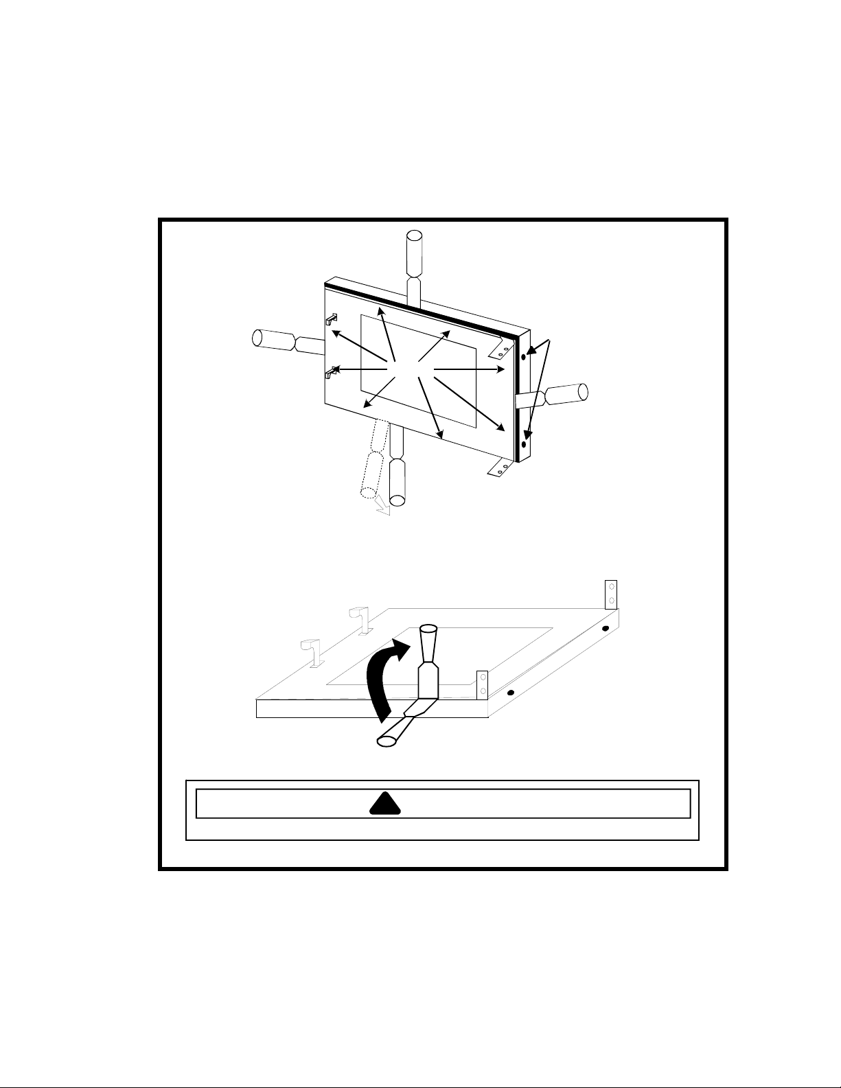
5. Before installing new tray, apply a generous bead of RTV on the front lip of cavity, (see below).
6. Install new tray and reseal using instructions supplied with the tray.
7. If arcing has damaged the oven door, replace inner oven door and inspect door ring weldment
for arcing.*
8. Replace door ring weldment if it is damaged.*
*To ensure proper operation, use the instructions in the Service Manual when reinstalling the
oven door.
Apply a generous bead
of RTV along this lip
before installing oven tray
Date July 31, 2001
No CR−236−B
EXCMW-125-B
Page 1 of 1
√Comm. Microwave Dehumidifier Dishwasher
Domm. Microwave √Export Comm. Heating Product
Laundry Product PTAC Products Range Product
Refrigerator/Fzr Room Air Cond.

9
Air Flow
A
ir filter must be in place
and cleaned regularly.
On two tube ovens:
To ensure proper
spacing and air flow,
air ducts must be
in place if oven is
installed in a closed
back installation.

10
Improved Filter for .6 Compact Ovens
New improved filter kit 12002550, is now available from Maytag Services and in production ovens beginning
December 2003.
The new filter is more durable, easier to remove, clean, and reinstall.
New filter kit part number 12002550 will replace old filter part numbers 12135801, 12135802, 12135803 and
12135804.
When servicing microwave ovens, make sure to check the air intake and exhaust for obstructions and for a clean
filter. Remember, cool components last longer!
Side retainers on older units
Bottom retainers on newer units.
Tabs
New Filter 12002550 - December 2003 and later
NOTE: When installing new style filter on older units with side retainers, it will be necessary to remove the securing
tabs located on each side of the filter. No modification is necessary when installing on units with bottom
retainers.
Old Style Filter 12135801, 12135802, 12135803, 12135804
prior to December 2003

11
Primary
Logic
Secondary
Monitor
Mounting
screws
Primary /
Logic
Monitor
Secondary
Mounting
screws
INTERLOCK SWITCHES
Monitor
Primary
Logic
Secondary
Mounting
screws
R0150154 Early Production Switch R0000277 Replacement for
Early Production Switch
12538901Q Later Production Switch
OR

12
SWITCH REPLACEMENT / DOOR ADJUSTMENT
!WARNING
To avoid risk of electrical shock, personal injury or death; disconnect electrical power before servicing.
1. Remove and retain two (2) screws securing
switch to cavity. Remove switch.
2. Position new switch assembly into cavity opening.
•First, insert bottom ramp of switch into bottom
opening.
•Tilt switch upward and insert top ramp of
switch into top opening.
•Be sure both ramps are fully protruded
through the front frame of cavity.
Primary
Logic
Secondary
Monitor
Cavity
Front
3. Loosely install screws removed in step 1.
4. Push and hold switch assembly towards front of
oven and tighten screws.
5. Transfer wires to new switch.
6. Secure wires to switch bracket using plastic wire
ties.
IMPORTANT: It is necessary to adjust the door
assembly for correct switch function.
7. Tape shims 12382602 and 12019302 to door, as
shown.
Shim
.060 in. \ 1.5 mm
Shim
.030 in. \ .75 mm
12019302
12382602
8. With door closed, loosen door hinge bolts 1/2
turn.
9. Lift upward on door, using the door handle.
10. With left hand, clamp door to cavity on hinge side
of door.
11. While holding door in place, tighten hinge bolts in
the order shown.
1
2
3
4
12. Open and close door several times to check
switch operation.
NOTE: If switches do not activate, check
condition and alignment of door and hinges.
13. Remove shims.

13
TOUCH PANEL and
CONTROL BOARD
F1
F2
F3
F4
F5
F6
Replace Board.
Replace Board.
Replace Board.
Replace Board.
Replace Touch Panel.
Replace Board.
Error
Codes

Disassembly
To avoid the risk of electrical shock, personal injury, or death, disconnect power to oven and discharge capacitors
before following any disassembly procedure.
14
Component Location
Interlock switch
assembly
Touch panel
Screws
Grease Shield
Diode location
2 magnetron
ovens
@MF SE T #13
@MF SET #13
@MF SE T #13
@MF SET #13
Oven Tray
Tray supports
Diode location
single magnetron
ovens
Capacitor
High Voltage Components

Disassembly
To avoid the risk of electrical shock, personal injury, or death, disconnect power to oven and discharge capacitors
before following any disassembly procedure.
15
Washer
NOTE: Raised rib on edge of washer
must face away from cavity.
Gear
NOTE: Ribbed side of gear
must face oven cavity.
Snap Ring
Antenna
Motor
Original
Clip
Magnetrons
Antenna
Motor
Antenna
assembly
bottom
Antenna
assembly
top
Replacement
clip
Shaft
High Voltage Components

Disassembly
To avoid the risk of electrical shock, personal injury, or death, disconnect power to oven and discharge capacitors
before following any disassembly procedure.
16
Control
board
Capacitors
Cavity
thermal
cutout
High Voltage
Transformer
Power cord
Blower
motor
Mounting bracket
Triac
Snubber
Magnetron TCO
Lamp and
receptacle
Spill
shield
Lamp
barrier
Line filter
(Located behind exhaust duct.)
Fuse
Terminal
Block
High Voltage Components

Component Specifications
!
WARNING
To avoid risk of electrical shock, personal injury or death; disconnect power to oven and discharge capacitor before
servicing, unless testing requires power.
17
Illustration Component Testing Results
Thermal Cutout Disconnect all wires from TCO.
Measure resistance across terminals.
Cavity Thermal Fuse ...................................
Magnetron TCO...........................................
Open: 104° C (219° F).
Open: 138° C (280° F.
Closed: 82° C (180° F).
1100 Watt units
1400, 1800, and 2100
Watt units
Diode Assembly Discharge Capacitors
Remove diode lead from capacitor and
connect ohmmeter.
Reverse leads for second test.
Infinite resistance should be
measured in one direction and 50KΩ
or more in the opposite direction.
NOTE: Test meter must contain a
battery of 6 volts minimum.
MT2
MT1 GATE
Triac Disconnect wires to triac.
Measure resistance from:
MT1 to MT2 .................................................
MT1 to Gate.................................................
MT2 to Gate.................................................
All terminals to ground.................................
Caution - Do not operate oven with
wire to terminal MT2 removed.
Infinite.
Approximately 40 Ωor more.
Infinite.
Infinite.
Capacitor Discharge Capacitors
Remove wires from capacitor terminals and
connect ohmmeter, set on highest
resistance scale to terminals.
Also check between each terminal and
capacitor case.
Between Terminals: Meter should
momentarily deflect towards zero
then return to over 5 MΩ. If no
deflection occurs, or if continuous
deflection occurs, replace capacitor.
Terminal to Case: Infinite resistance.
Snubber Assembly Disconnect wires to snubber.
Measure resistance across terminals .............
Infinite.
Magnetron Discharge Capacitors
Remove wires from magnetron and
connect ohmmeter to terminals. Also check
between each terminal and ground.
Between Terminals: Less than 1 Ω.
Each terminal to ground measures
Infinite resistance.
NOTE: This test is not conclusive. If
oven does not heat and all other
components test good replace the
magnetron and retest.
Blower Motor Remove all wires from motor.
Measure resistance across coil ......................
Approximately 30 Ω.
Earth
Load
Line
Line filter Measure resistance:
Line to Line ..................................................
Load to Load................................................
Line to Load.................................................
Any terminal to Earth...................................
.8 M Ω.
.8 M Ω.
Continuity.
Infinite.
Wire Harness Test resistance of wires .................................. Continuity.

Component Specifications
!
WARNING
To avoid risk of electrical shock, personal injury or death; disconnect power to oven and discharge capacitor before
servicing, unless testing requires power.
18
Illustration Component Testing Results
COM
220 230
46
5
Transformer
1100 Watt
4
3
5
6
(COM)
1
(230V)
Discharge Capacitor
Remove all wires from terminals, and
measure resistance from:
220 to Common............................................
230 to Common............................................
Terminal 5 to 6..............................................
Terminal 4 to Earth screw on transformer....
Terminal 4 to any other terminal ..................
Gray Pink
1
3
This transformer is equipped with a
155° C thermal cutout.
1.3 Ω.
1.3 Ω.
<1 Ω.
70 Ω.
Infinite resistance. If not, replace
transformer.
COM230
4
7
65
8
Transformer – 1400,
1800, and 2100
Watt
# 4
# 1
# 2
# 5
# 6
# 7
# 8
Discharge Capacitor
Remove all wires from terminals, and
measure resistance from:
230 to Common............................................
Terminal 5 to 6..............................................
Terminal 7 to 8..............................................
Terminal 4 to Earth screw on transformer....
Terminal 4 to any other terminal ..................
1 Ω.
<1 Ω.
<1 Ω.
38 - 45 Ω± 5%.
Infinite resistance. If not, replace
transformer.
Stirrer motor Remove all wires from motor.
Measure resistance across terminals ..............
Approximately 12 KΩ.
Interlock switch
assembly
Primary
Secondary
Monitor
Disconnect wires to switch.
With door open measure resistance from:
Terminal C to NO Primary .......................
Terminal C to NO Secondary ..................
Terminal C to NC Monitor........................
With door closed measure resistance from:
Terminal C to NO Primary .......................
Terminal C to NO Secondary ..................
Terminal C to NC Monitor........................
Door Closed
C
C
C
NC
NO
NO
Primary
Secondary
Monitor
Infinite.
Infinite.
Continuity.
Continuity.
Continuity.
Infinite.

Component Specifications
!
WARNING
To avoid risk of electrical shock, personal injury or death; disconnect power to oven and discharge capacitor before
servicing, unless testing requires power.
19
Illustration Component Testing Results
Pin #1
Pin #1
P1
P2
ABCJFK
Controller board
P2
110
P1
110
P1 connector
used for touch
panel ribbon
Line voltage to control board
P2 connector
Pin 1—Pin 3.....................................
Output drive voltage to triac
Triac terminals...................................
Gate—T1 .........................................
Fan relay (controls blower motor,
antenna motor(s), and oven light)
Control board.....................................
Terminals C—J................................
Cook relay
Control board.....................................
Terminals F—K................................
Line voltage (All Conditions)
0 VAC (Idle and Standby)
0.9 VAC (Cook)
Line voltage (Idle)
0 VAC (Standby and Cook)
Line voltage (Idle)
0 volts (Standby and Cook)
ERROR CODES
F1.......... Replace Control Board
F2.......... Replace Control Board
F3.......... Replace Control Board
F4.......... Replace Control Board
F5.......... Replace Touch Panel
F6.......... Replace Control Board
Touch Panel
Assembly
Continuity is indicated as 100 Ωand
below.
Pin 1: Ground.
1
2
3
4
5
6
7
8
9
Split
10
Pad
1
2
3
4
5
6
7
8
9
0
Start
Stop/Reset
Power Level
X 2
Time Entry
Trace
(measure both)
8 & 1, 10 & 1
7 & 1, 10 & 1
6 & 1, 10 & 1
5 & 1, 10 & 1
4 & 1, 10 & 1
3 & 1, 10 & 1
8 & 1, 9 & 1
7 & 1, 9 & 1
6 & 1, 9 & 1
5 & 1, 9 & 1
4 & 1, 9 & 1
4 & 1, 8 & 1
5 & 1, 8 & 1
6 & 1, 8 & 1
7 & 1, 8 & 1
Measurement
Continuity.
Continuity.
Continuity.
Continuity.
Continuity.
Continuity.
Continuity.
Continuity.
Continuity.
Continuity.
Continuity.
Continuity.
Continuity.
Continuity.
Continuity.
Touch Panel
Assembly
Continuity is indicated as 100 Ωand
below.
Pin 1: Ground.
Pad
1
2
3
4
5
6
7
8
9
0
Start
Stop/Reset
Power Level
X 2
Time Entry
Trace
(measure both)
8 & 1, 10 & 1
7 & 1, 10 & 1
6 & 1, 10 & 1
5 & 1, 10 & 1
4 & 1, 10 & 1
3 & 1, 10 & 1
8 & 1, 9 & 1
7 & 1, 9 & 1
6 & 1, 9 & 1
5 & 1, 9 & 1
4 & 1, 9 & 1
4 & 1, 8 & 1
5 & 1, 8 & 1
6 & 1, 8 & 1
7 & 1, 8 & 1
Measurement
Continuity.
Continuity.
Continuity.
Continuity.
Continuity.
Continuity.
Continuity.
Continuity.
Continuity.
Continuity.
Continuity.
Continuity.
Continuity.
Continuity.
Continuity.
Conditions
Initial Power Up Condition: Apply power to oven with door closed.
Idle Condition: Oven plugged in, display blank (no other components operating).
Standby Condition: Open oven door, light and motors operate.
Cook Condition: Food load in oven, cook cycle initiated.

Power Testing Procedure
!
WARNING
To avoid risk of electrical shock, personal injury or death; disconnect power to oven and discharge capacitor before
servicing, unless testing requires power.
20
All Amana and Menumaster microwave oven power outputs are rated using the IEC705 standards. Using the
IEC705 test method requires precision measurements and equipment that is not practical to be performed in the
field. Using the test shown below will indicate if the oven performance is satisfactory.
Test equipment required:
•1000 ml test container and thermometer (Power test kit 1000100006).
•Digital watch / watch with a second hand for use on ovens with electromechanical timers.
Important Notes:
•Low line voltage will cause low temperature rise / power output.
•Ovens must be on a dedicated circuit, properly grounded, and polarized. Other equipment on the same
circuit may cause a low temperature rise / power output.
•This test and results are not a true IEC705 test procedures and are only intended to provide servicers with
an easy means of determining if the microwave oven cooking output is correct.
Procedure
1. Fill the test container to the 1000 ml line with cool tap water.
NOTE: Water temperature should be approximately 60° F / 16° C.
2. Using the thermometer, stir water for five to ten seconds; measure, and record the temperature (T1).
3. Place test container of water in the center of oven cavity and close door.
4. Heat the water for a 33-second full power cycle.
NOTE: Use a digital watch or a watch with a second hand for ovens with electromechanical timers.
5. At end of the cycle, remove test container. Using the thermometer, stir water for five to ten seconds and record
temperature (T2).
6. Subtract the starting water temperature (T1), from the ending water temperature (T2) to obtain the temperature
rise (∆T).
7. If the temperature rise (∆T) meets or exceeds the minimum, the test is complete. If the temperature rise (∆T)
fails to meet the minimum temperature rise, test the line voltage to verify it is correct. Then repeat steps 1-6
making sure to change the water. If the temperature rise (∆T) fails to meet the minimum temperature rise again
the oven will require service.
Minimum Temperature Rise at Thirty -Three (33) Seconds Run Time
∆T Cooking ∆T Cooking ∆T Cooking ∆T Cooking
(°F) Power Output (°F) Power Output (°C) Power Output (°C) Power Output
10..................1000 20 .................2000 5 ...............1000 11 ............2000
11..................1100 21 .................2100 5.5 .............1100 11.5 .........2100
12..................1200 22 .................2200 6.5 .............1200 12 ............2200
14..................1400 24 .................2400 7.5 .............1400 13 ............2400
17..................1700 25 .................2500 9.5 .............1700 13.5 .........2500
18..................1800 27 .................2700 10 ..............1800 15 ............2700
19..................1900 30 .................3000 10.5 ...........1900 16.5 .........3000
This manual suits for next models
34
Table of contents
Other Amana Microwave Oven manuals

Amana
Amana AMC1070 User manual

Amana
Amana MVH140E User manual

Amana
Amana MVH130 User manual

Amana
Amana AMV5206AA User manual

Amana
Amana XPRESS AXP22 User manual

Amana
Amana AMV2307PFW User manual

Amana
Amana AMV6502REW User manual

Amana
Amana F1340E User manual

Amana
Amana ACO1840AB User manual

Amana
Amana AMC5143BCB/W/Q User manual

Amana
Amana AMC4080AAQ User manual

Amana
Amana AMC4322 User manual

Amana
Amana RC517 User manual

Amana
Amana AMV6502RES User manual

Amana
Amana RSBG669T User manual

Amana
Amana Menumaster DECS11MA Assembly instructions

Amana
Amana RFS9 Series User manual

Amana
Amana RFS12SW2C User manual

Amana
Amana AMC4322GS User manual

Amana
Amana RFS511MP Series User manual