Date de mise à jour : 28/01/2004 - FT 093 - Révision 04 - FR / GB / NL Page 6 sur 15
GAZ / GAS IMPORTANT/ BELANGRIJK
FR L’ INSTALLATION DOITETRE REALISEE CONFORMEMENT AUXREGLEMENTATIONS ET NORMES EN VIGUEUR .
GB THE APPLIANCE MUST BE INSTALLED IN ACCORDANCE WITH THE APPLICABLE REGULATIONS AND STANDARDS.
NL DE APPARATEN MOETEN VOLGENS DE GELDENDE DE WEITTEN EN VOORSCHRIFTEN WORDEN GEINSTALLEERD.
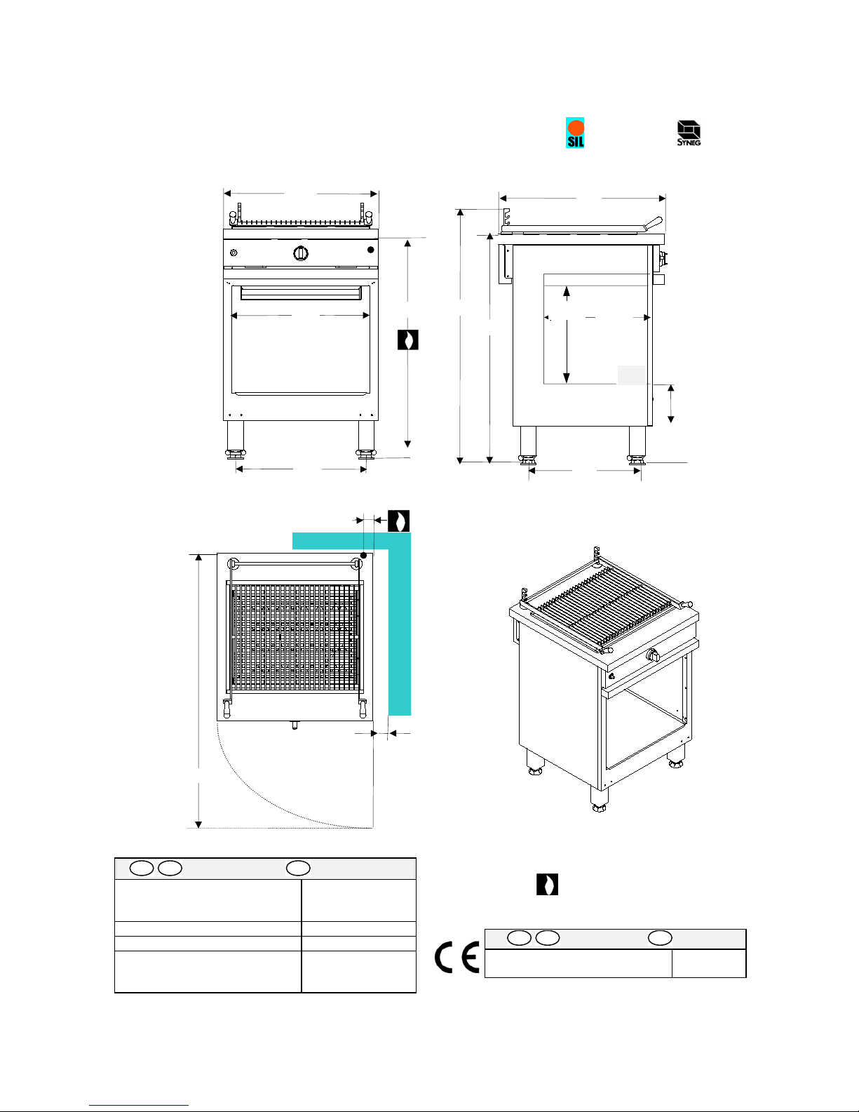
FR Nota : Cet appareil est de type Anon
raccordé à un conduit d’évacuation.
GB Note : This is a type Aappliance and is not
connected to a ventilating flue.
NL N.B.: Dit apparaat is van het type A- niet
aangesloten op een afvoerleiding.
Tableau Type Pression / Pressure / Druk m3/h/kW
Table G 20 20 mbar 1,46
Tabel G 25 20 mbar 1,60
1G 25 25 mbar 1,60
G 30 28-30 mbar 1,12
G 30 50 mbar 1,12
G 31 37 mbar 1,39
G 31 50 mbar 1,39
Avant raccordement / Before connection / Voor het aansluiten
FR Vérifier : - Le parfait état de propreté des canalisations, afin d’éviter l’obstruction des injecteurs et le
dysfonctionnement des têtes magnétiques. Le gaz pour lequel l’appareil à été réglé : plaquette signalétique (Afig. 1) et
marquage. La compatibilité de la section des canalisations d’alimentation avec la puissance de l’appareil (suivant
fiche technique). La conformité du débit d’air neuf (voir tableau 1).
GB Check : - Pipework is perfectly clean in order to prevent the injectors becoming blocked and malfunctioning of
the magnetic heads. The gas for which the appliance was set up: rating plate (A fig. 1) and markings. Cross-sectional
area of gas supply pipework is compatible with the appliance’s thermal output (as per technical data sheet). Correct
fresh air flowrate (See table 1).
NL Eerst controleren : - Of de buisleidingen volkomen schoon zijn, om verstopping van de injectors en storingen in
de werking van de magneetkoppen te voorkomen. Voor welk soort gas het apparaat is ingesteld: zie
konstruktieplaatje (Afig. 1) en markering. Of de doorsnede van de toevoerbuizen afgestemd is op het vermogen van
het apparaat (zie technische gegevens sheet van het apparaat). Juiste doorvoerhoeveelheid verse lucht (zien tabel 1).
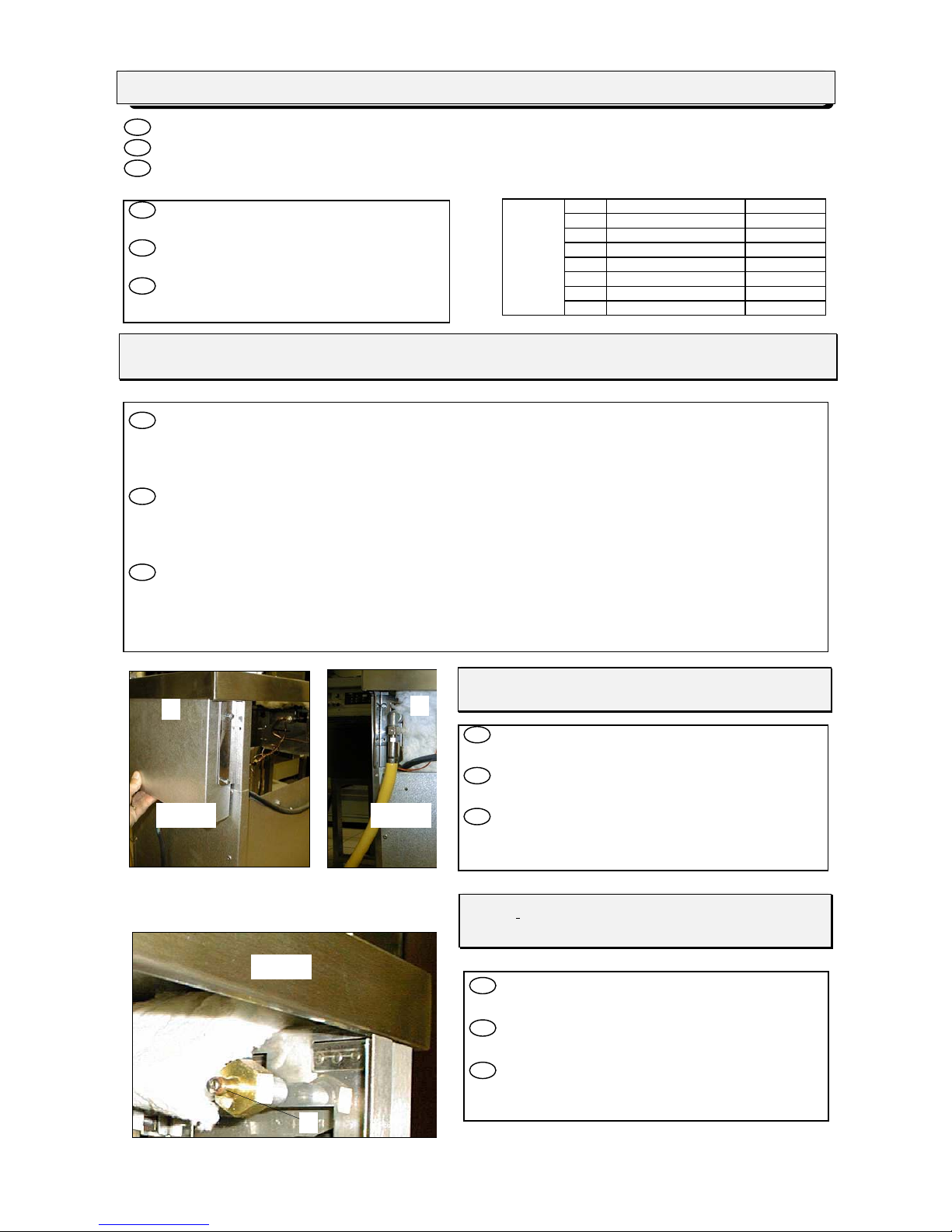
Raccordement / Connection / Aansluiten
FR Déposez le capot arrière A(fig. 2). Raccord femelle Ø
15/21, filetage 1/2” gaz sur B(fig. 3).
GB Remove rear cover A (fig. 2). Female coupling Ø
15/21, 1/2” gas thread on B(fig. 3).
NL Verwijder het achterpaneel A (fig. 2). Vrl. koppeling
Ø 15/21, schroefdraad 1/2” gas op B(fig. 3).
Après raccordement / After connection /
Na het aansluiten
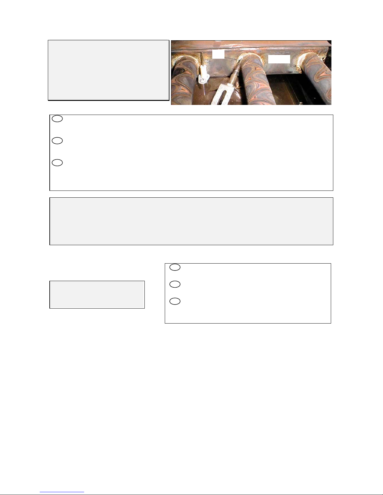
FR - Contrôler la pression d’alimentation sur prise de
pression C(fig. 4).
GB - Check the supply pressure on pressure connection
C (fig. 4).
NL - Controleer de toevoerdruk op drukmeetnippel C
(fig. 4).
AB
Fig. 2 Fig. 3
C
Fig. 4