Ambient Lockit+ User manual

Firmware Version 7.0

02Lockit+ Users manual |
Table of contents
1. Introduction . . . . . . . . . . . . . . . . . . . . . . . . . . . . . . . . . . . . . . . . . 03
2. Unit Description . . . . . . . . . . . . . . . . . . . . . . . . . . . . . . . . . . . . . . 05
3. LED Blink Code . . . . . . . . . . . . . . . . . . . . . . . . . . . . . . . . . . . . . . . 06
4. Powering . . . . . . . . . . . . . . . . . . . . . . . . . . . . . . . . . . . . . . . . . . . . 07
5. Display . . . . . . . . . . . . . . . . . . . . . . . . . . . . . . . . . . . . . . . . . . . . . . 08
6. Basic Button Operations . . . . . . . . . . . . . . . . . . . . . . . . . . . . . . . 09
7. Operation Modes . . . . . . . . . . . . . . . . . . . . . . . . . . . . . . . . . . . . . 10
8. Access the Web Interface . . . . . . . . . . . . . . . . . . . . . . . . . . . . . . 13
9. Features of the Web Interface . . . . . . . . . . . . . . . . . . . . . . . . . . 14
10. Useful Links. . . . . . . . . . . . . . . . . . . . . . . . . . . . . . . . . . . . . . . . . 21
11. Appendix . . . . . . . . . . . . . . . . . . . . . . . . . . . . . . . . . . . . . . . . . . . 22

03Lockit+ Users manual |
1. Introduction
Lockit+
The Lockit+ combines the state of the art, high-accuracy Ambient Lockit
Timecode and Sync technology with advanced metadata management options
to improve your workow between set and editing.
It’s the successor of both the MasterLockit and MasterLockitPlus. A lot of user
input has gone into further development to make the Lockit+ the true agship
of the Lockit family.
Highly Accurate Timecode and Sync Generator
For over 30 years, Ambient Timecode has been synonymous with precision
and reliability. Like the Lockit, the Lockit+ provides all timecode and sync for-
mats and full ACN compatibility.
But wait… there is more! We called it Lockit+ because of its modular design
and the many added values.
+ Modular Hardware Design
The Lockit+ is available with dierent extensions. They oer additional in-
terfaces (like USB or SuperSlot) to serve dierent situations on set or in the
studio.
+ WiFi Access & Web Interface
The built-in server spans a local WiFi, giving users browser-based access to
all the Lockit+ features via mobile device or computer.
+ Advanced Control and Monitoring
The web interface of the Lockit+ gives access to advanced generator settings
and monitoring of all Lockit devices within the ACN.
+ Metadata Hub
The Lockit+ can extract technical metadata from compatible cameras to
broadcast it via WiFi to the Ambient LockitScript App for script supervisors.
+ Lens Metadata Processing
The Lockit+ stores key Cooke /i lens metadata frame-accurately in an
open le format - at the same time it makes the data accessible live via
WiFi or ethernet.

04Lockit+ Users manual |
+ Frequency Scanning
Plug the separately available antenna into a USB port of the Lockit+ to per-
form a full frequency scan. In the web interface you get concrete suggestions
for available frequencies for your transmitters and receivers.
+ Remote Control
Use the web interface of the Lockit+ to remotely control your Sound Devices
6 or 7 series recorders.
+ More to come
The Lockit+ design is future-proof. The modular approach allows to elegantly
oer further applications and extensions in the future.
ACN stands for Ambient Communication
Network and is our own wireless network.
It utilizes an extremely reliable, proprietary 2.4GHz network with
16 selectable channels for communication to minimize lag and
interference with other radio sources. All gathered information
is buered until it is successfully received and stored.
The ACN is used to interchange timecode related information
including time, frame rate and user bits as well as device meta-
data between Lockits or third-party devices with built-in Lockit
Module.
Learn more about the beauty of ACN here:
https://ambient.de/en/acn-technology

05Lockit+ Users manual |
2. Unit Description
Front
1Blue TC & ACN Connector (LEMO-compatible)
2Yellow TC & Sync Connector (LEMO-compatible)
3 ACN Antenna, SMA RP 2.4GHz, keep attached to unit
4 WiFi Antenna, SMA RP 2.4GHz, keep attached to unit
5 RGB Status LED
6OLED Display
7Power Button
8Red Button
9 Green Button
10 Battery Compartment (2x BX1)
Standard Extension
AUSB-A connector
BUSB-C connector (also for powering)
CUSB-C connector for Midi TC (future feature)
DBlue TC & ACN Connector (LEMO-compatible)
E Hirose (for external powering)
A
C
E
B
D
17892
4
5
6
10
3

06Lockit+ Users manual |
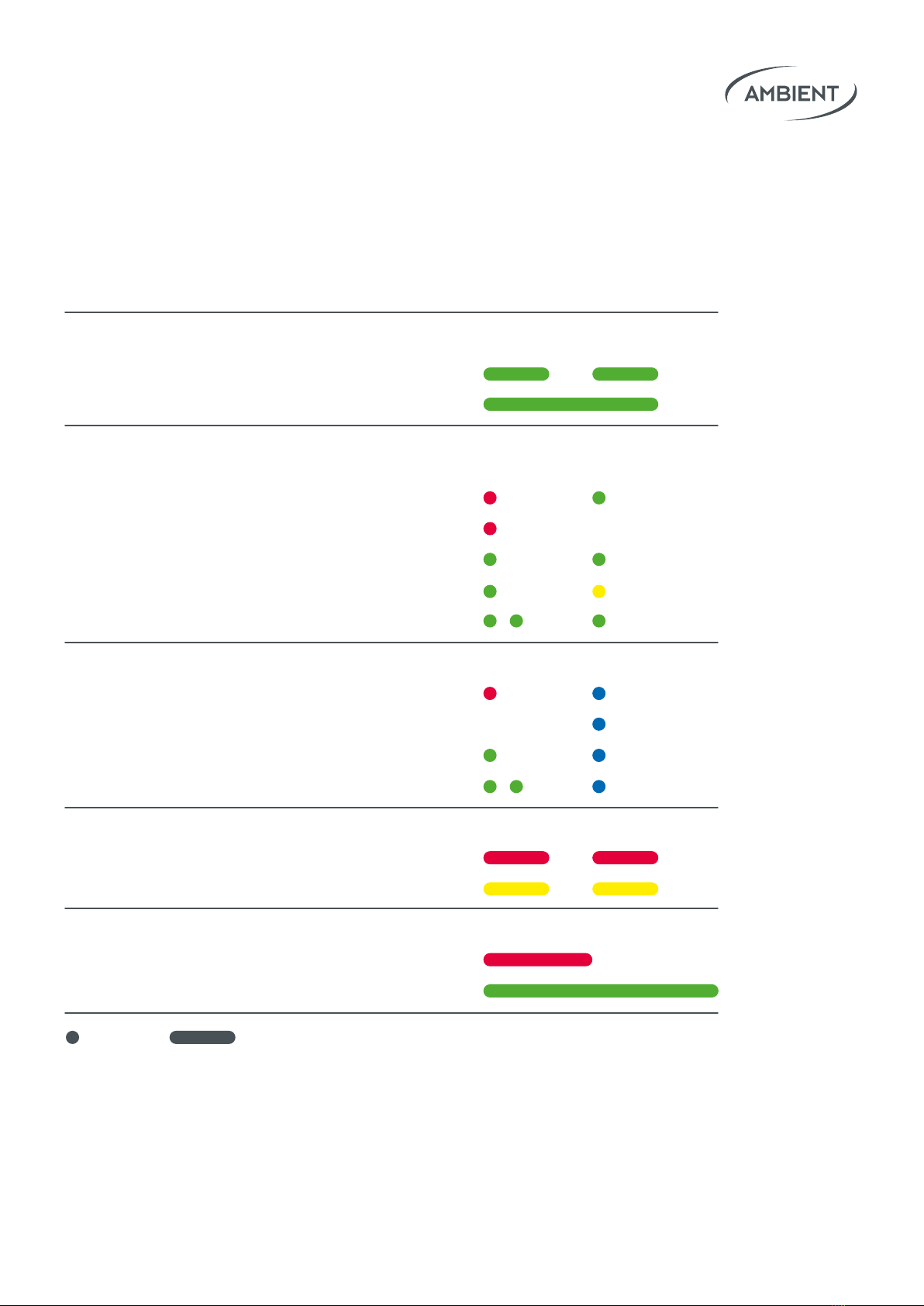
3. LED Blink Code
Mode 1sec 2sec
ACN Jam (C-Jam, TX, Single)
Jam transmitted / sent
Jam received
Lockit, NanoLockit, LockitSlate Take2,
Lockit+ (in standby) or LockitModule
TC out mute; will start with preference
TC out mute; will start from fallback zero
TC out active
TC out active; output level reduced
TC out active; low battery
Lockit+ with WiFi active
TC out mute; will start with preference
TC out mute; will start from fallback zero
TC out active
TC out active; low battery
TX Mode Warnings
TC out mute; no initial LTC source
TC out active; LTC source lost/stopped
Charging Mode, Unit o
ext. Power, charging
ext. Power, fully charged
blinkash

07Lockit+ Users manual |
4. Powering
The Lockit+ can be powered by 6 to 24 Volts DC via a Hirose 4-pin connector,
pin 1 carrying GND pin 4 positive voltage. Supply ratings and typical values in
operation:
6V DC min. rating 3.5A, 12V DC min. rating 1.7A, 24V DC min. rating 1A
Alternatively, you can also power the Lockit+ via the USB-C socket.
Supply rating: 5V min. rating 3A
It is also possible to run the Lockit+ only with the two included BX1 batteries.
Please make sure to only change the batteries one after the other. This work-
ow keeps the timecode running while the unit is switched on and also main-
tains the real-time clock when switched o. In basic operation the batteries
will last for up to 4 hours.
1.
2.
If the Lockit+ is switched o and power is applied, the LED will slowly blink red
to indicate charging of the batteries. Fully charged, the LED will be lit perma-
nently green.
If the Lockit+ is in operation the charging status and the connected external
power supply are shown in the display.
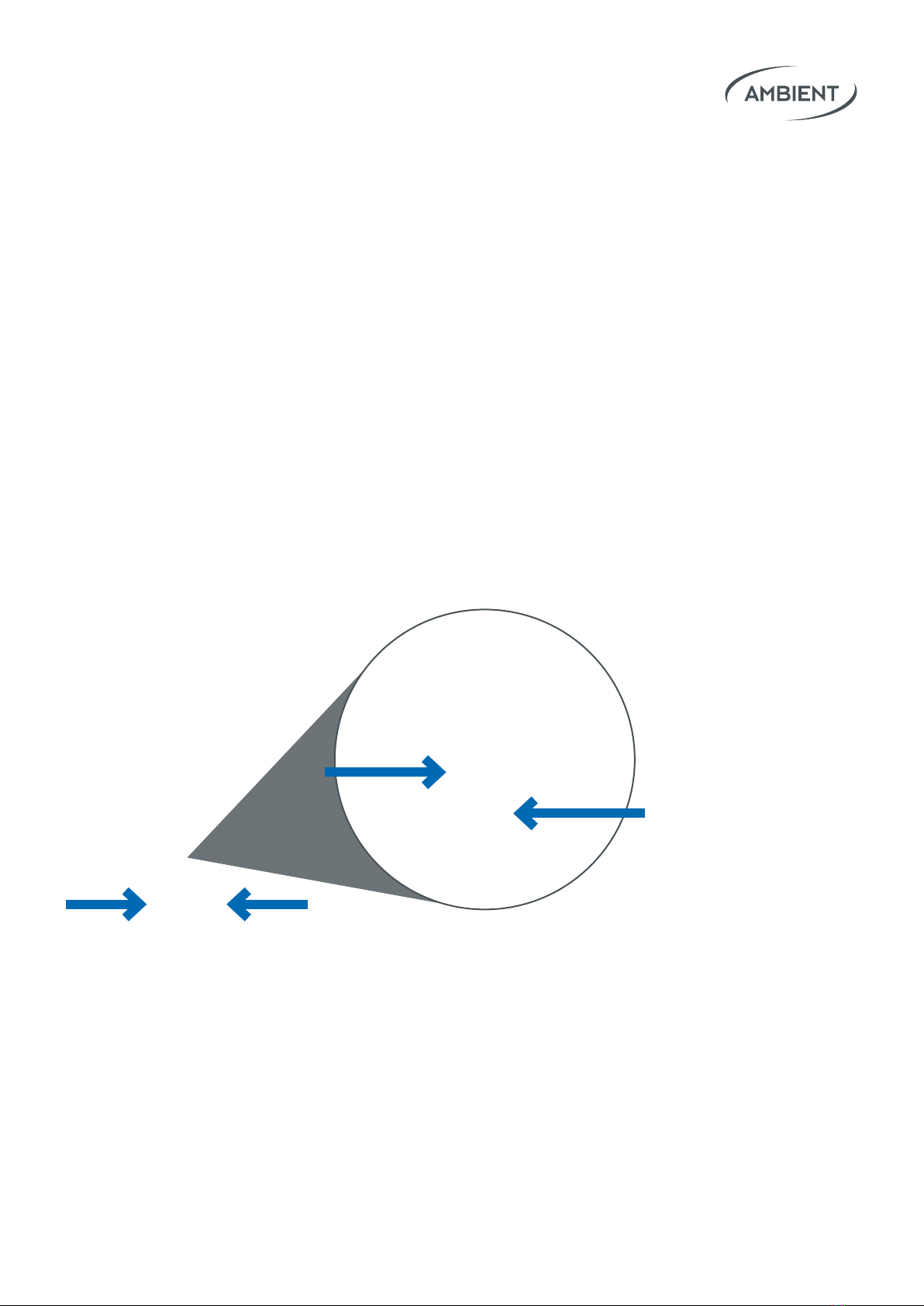
Note: To change batteries please push the
battery release levers.
Please assure to push the levers down
before inserting the batteries.

08Lockit+ Users manual |
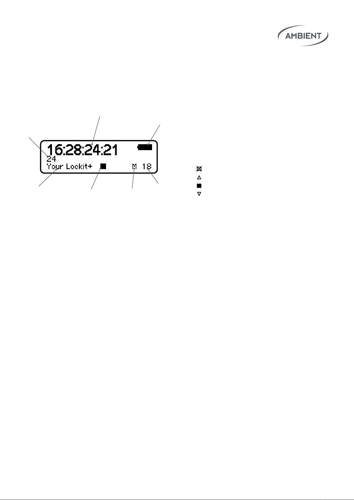
5. Display
5
467
3
1
2
1Timecode
2Project Rate (FPS)
3 Battery Status / Ext. Power
4 Unit ID / Unit Name
5 Status WiFi
O/Standby
Starting
On
Shutting down
6 ACN Mode
7 ACN Channel

09Lockit+ Users manual |
6. Basic Button Operations
Turn On: Press and hold Power until LED lights green to start unit.
Turn O: Press and hold Power for 5 seconds until power o menu
appears. Continue with additional button presses:
Power: Shutdown
Red: Standby*
Red & Green: Reset WiFi / LAN settings
Access Menu: While the unit is running you can access the menu
by pressing Red & Green simultaneously.
There you can easily set:
• Project Rate
• Sync Output
• ACN Channel
Tap Red & Green simultaneously to conrm and proceed.
Tap Red to decrease or Green to increase a parameter value.
Reset: When switched o, press and hold Red & Green
simultaneously to perform a factory reset of the Lockit Module.
All data on the web interface remains untouched.
*Lockit Module running, web interface shut down

10Lockit+ Users manual |
7. Operation Modes
Within the ACN there is always one Lockit device acting as timecode transmit-
ter, broadcasting timecode and frame rate to the Receivers. You can choose
between C-Jam, TX and Single Jam Mode.
7.1 C-Jam Mode (Continuous Jam)
In C-Jam Mode we utilize our ACN network to completely prevent any drift. In
this mode one Lockit device acts as a C-Jam Master. It sends a pulse through
the ACN every six seconds to constantly align with all other Lockit boxes.
To start the unit as C-Jam Master press and hold Green, then tap Power.
Press and hold Green to conrm the timecode and start the C-Jam.
The icon on the display will switch to M.
All other Lockits (that are on the same ACN channel) will now automatically
follow the C-Jam Master and display an ACN icon at the lower right of the
display.
The Lockit+ will remember that it has been set to C-Jam Master. It will
automatically start in C-Jam master Mode when booted via the power button
afterwards. You can also start and stop the C-Jam Mode and adjust your start-
up preferences in the Lockit+ web interface.
Since even in C-Jam Mode every unit still uses its own VCO (voltage-controlled
oscillator) to generate timecode (and sync), they don’t necessarily have to be
in range of the C-Jam master constantly to be accurate.
On the display you will see an (M)
appear, indicating that the device
is ready to go.

11Lockit+ Users manual |
Lockit devices that are powered up at a later point in time will automatically
follow the C-Jam Master and set their timecode and frame rate accordingly.
Note: Just one unit is allowed to be the C-Jam Master within an ACN channel. A
second master will be blocked and will also automatically follow the C-Jam Master
and display an ACN icon at the lower right of the display.
7.2 TX Mode (Transceiver Mode)
The TX Mode basically works like the C-Jam Mode, with the dierence that
the TX Master receives timecode and frame rate from an external source via
cable. Main use cases are playback situations (e.g. music video shootings).
To start the unit as TX Master press and hold Red, then tap Power.
On the display you will see TX appear.
As soon as the external source sends timecode, the TX Master will broadcast
it via ACN to all other Lockits. They will display an ACN icon at the lower right
of the display.
As soon as the external source stops sending timecode to the TX Master, the
timecode on all Lockits will freeze, and they will start ashing yellow. As soon
as the timecode starts running again, they’ll ash green again.
Note: to make the TX Mode work, all Lockit Devices must run on the latest rm-
ware. (7.xx)

12Lockit+ Users manual |
7.3 ACN Receiving Mode
All Lockit devices that are jammed via a C-Jam or TX Master automatically
switch to ACN Receiver Mode, indicated by the ACN logo in the lower right of
the display.
Lockit devices in ACN Receiving Mode constantly follow the current C-Jam or
TX Master.
To power up just long-press Power.
Lockit devices that are powered up at a later point of time will automatically
switch to ACN Receiver Mode after having received a jam via ACN. Their time-
code and frame rate will be set accordingly.
7.4 Single Jam Mode
In Single-Jam Mode you can send a one-time pulse through the ACN to sync
all Lockit devices. From then on, each Lockit continues to run autonomously.
This is perfectly ne for most occasions, as our Lockit devices are highly
accurate and drift less than a frame within 24 hours.
To power up just long-press Power.
All Lockit devices in this mode can send and receive a Single Jam. Choose
one of your Lockits and press Green for 3 seconds until the green LED
lights up twice.
This way timecode and frame rate gets broadcasted to the other Lockit box-
es in the same ACN channel.
Note: Once a Lockit device is turned o the timecode generator stops. After turning
on again you must perform the Single Jam again.
That’s why we recommend C-Jam Mode over Single Jam Mode, as it
completely eliminates drift and is more convenient to use.

13Lockit+ Users manual |
Good to Know: Plug and Play Timecode
Instead of using the graphical menu of the Lockit+ (pressing
Red & Green at once) or the web interface - feed in time-
code and frame rate externally.
Just plug the Lockit+ to the TC Out port of another device (e.g.
your Sound Recorder) and it will automatically take over time-
code and frame rate.
This only works if no Single Jam has been sent - or a C-Jam / TX
Master is active in the ACN channel. Indicated by the LED ashing
red and green alternately.
If the device is already jammed and you attach an external time-
code source, you can enter the “Compare Screen”. This displays
a potential timecode drift between external source and your
Lockit.
The built-in server spans a local WiFi, giving users browser-based
access to all the Lockit+ features via mobile device or computer.
Per default the WiFi name and password are both the serial number
of your Lockit+.
Once connected to the WiFi of your Lockit+, you can access the web
interface by entering ”10.0.0.1” or “serialnumber.local” in the address eld
of your browser (z.B. Chrome, Firefox, Safari, Edge …)
If you forgot your WiFi password, you could reset the WiFi and LAN settings
in the shutdown menu. Long-press Power, then press Red & Green
simultaneously.
8. Access the Web Interface

14Lockit+ Users manual |
9. Features of the Web Interface
9.1 Generator Tab
Comprehensive conguration of the internal generator of the Lockit+
•Set the real-time clock (RTC) and the date format
•Start the timecode and set a startup preference
• RTC
• RTC-12
• Manual
• Set your project rate
• FPS: 23.98/24/25/29.97/29.97 DF/30/
47.95/48/50/59.94/59.94 DF/60/60 DF
•Change Userbits
• date with format ED/AD
• date
• date without year
• manual
• Congure Yellow Sync Connector
• Wordclock (o, 48kHz, 96kHz, 192 kHz)
• Video Sync (o, PsF, p, i : depending on selected project rate)
• PPF Sync (o, Multiplier 1x, 2x, 4x)
• Congure Blue ACN Connector
• Metadata In/Out
-Metadata device (RED DSMC2 or Sound Devices 6 or 7 series)
-Lens data (Cooke/I³)
-RED DSMC2 (Lockit+ is not running in C-Jam Mode)
Note: RTC-12 automatically sets Start TC to
RTC in the mornings or RTC-12 after 1pm.
Note: ED/AD stands for european/american
date format

15Lockit+ Users manual |
9.2 ACN Settings
Monitor and manage all Lockits within the selected ACN channel.
• “Your Lockit+”
• Start C-Jam master
• Select ACN channel
• Rename unit
•ACN Radar
• Check status of connected devices (online/oine)
• Grid view and list view of ACN devices
- Online / oine
-Rename units
-Battery status
-Timecode aberration
• Project tune devices
Note: If you want to re-calibrate your Lockit Setup after some years of operation,
you can perform a Project Tune (former feature of the discontinued ACC controller).
All Lockits within the selected ACN Channel will be tuned simultaneously.
The process will take approx. 2 minutes during which the devices will rapidly blink
red and green.
Tune value will be overwritten by the factory value on a factory reset.
Attention: NEVER initiate a Project Tune during a shoot. There will be a hard reset
of the sync pulse when the process is nished. This will potentially bring cameras
in operation out of clock and compromise active recordings.

16Lockit+ Users manual |
9.3 Radio Wizard
Plug the separately available antenna ACN-RF (A80958) into the USB port
and open the Radio Wizard tab in the Web Interface to perform a full
frequency scan. The frequency range may be set from 100 MHz to 1500 MHz.
You will get concrete suggestions for available frequencies for your trans-
mitters and receivers. Intermodulations caused by your wireless audios will
also be displayed.
Open the Radio Wizard tab and create your rst setup. Setup denes all the
transmitters / reciecers you currently use in your sound bag or sound cart.
You can use the same setup for the whole production or create separate
setups for dierent locations. The latter makes sense if you want so safe
radio network scans for a later point.

17Lockit+ Users manual |
After creating your setup, you need to add systems. System means the
product type of a transmitter set (e.g.: Lectrosonics Block 32 or Wisycom
MCR54) Please insert the following parameters of your wireless system:
• min frequency (MHz)
• max frequency (MHz)
• step size (kHz)
• Window size (MHz, optional)
• Count of items
Within those systems you create dierent items. Each item will represent a
concrete wireless Transmitter / Receiver.
Afterwards click on Scan & Coordinate to run a scan in the range of your setup.
The range is automatically calculated from the lowest min frequency and the
highest max frequency of all your created items / systems.
If you encounter any problems with a suggested frequency, there are dierent
options for new coordination or a recoordination of a single item.

18Lockit+ Users manual |
9.4 Sound Recorder
Use the web interface of the Lockit+ to remotely control your Sound Devices
6 or 7 series recorders. When congured correctly you can prepare and edit
scene, take, notes, arm and rename tracks, remote roll your recorder, circle
takes and, in the end, create comprehensive sound reports.
Note: the available options and behavior strictly depend on the protocol made
available by Sound Devices. For example, reading meter status is only available
for 788T.
For series 7 connect the cable MLC-CL (A80339) from the Blue ACN connector
to the C.Link-in port. For series 6 connect the cable MLC-HID from the Blue
ACN connector to the USB-A port.
Now you can enable the data connection to your Sound Devices Recorder by
choosing "metadata device" in the Blue ACN Connector panel within the Gen-
erator menu.
Note: a separate timecode cable is needed to jam timecode to your Sound Devices
recorder. Please set the timecode to "external" in the menu of your Sound Devices
recorder.

19Lockit+ Users manual |
9.5 Lens Metadata
The Lockit+ stores key Cooke/i lens metadata frame-accurately in an open
le format (supported protocol: Cooke/i3 - “i cubed”). Record lens data on
the internal web server or connect an USB stick for recording.
To do so connect the metadata interface of the lens with the blue ACN
connector of the Lockit+ with the ACN-CP (A80962).
Live lens data is also available via WiFi or Ethernet. The API is available on
request. Please contact: [email protected]
9.6 System
In the System Panel you see the serial number and rmware version of both
of your Lockit+ and the built-in Lockit Module.
Please check https://ambient.de/en/downloads to get the latest rmware
updates. To perform an update the Lockit+ needs to be externally powered.
You can also congure the WiFi settings (host or client) and the LAN settings
if a LAN-adapter is connected to the Lockit+.
If you forgot your WiFi password, you could reset the WiFi and LAN settings
in the shutdown menu. Long-Press Power, then press Red & Green
simultaneously.
There is also an auto power option available. If enabled and the Lockit+ is
externally powered, it will automatically start up.

20Lockit+ Users manual |
9.7 Metadata Workow with LockitScript App
To make camera metadata (e.g. clip name, lens, ISO etc.) show up in the
LockitScript App, the iPad must be connected to the Lockit+ in C-Jam
Mode via WiFi.
Compatible cameras:
•ARRI CAP2 cameras
•RED DSMC2 cameras
The basic principle is that Lockit boxes on the cameras send the metadata
via ACN to the Lockit+ in C-Jam Mode. From there, all collected metadata is
sent via WiFi to the iPad with the LockitScript App.
ACN
ACN
WiFi
Workow for ARRI CAP2 cameras:
• Connect a Lockit+ to the ethernet port of the camera.
• Required cable: MLC-L1B10P
• In the camera menu activate CAP2 and leave the CAP2 password
at its default "arri".
• Make sure both the connected Lockit+ and the camera operate in
LAN Mode “Static”.
• The default IP of the camera is "192.168.0.100".
• Congure your Lockit+ LAN adapter to use a static IP in the same
network (e.g. 192.168.0.101).
Table of contents
Other Ambient Portable Generator manuals
Popular Portable Generator manuals by other brands

Ryobi
Ryobi RYI2000T Operator's manual

Generac Power Systems
Generac Power Systems 005723-0 GP Series owner's manual

EINHELL
EINHELL TC-PG 25/E5 Original operating instructions

Heavy Duty Power Systems
Heavy Duty Power Systems HDD7000E owner's manual

WhisperPower
WhisperPower Piccolo Genverter installation manual

Wacker Neuson
Wacker Neuson G 100 Operator's manual