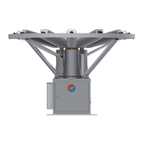
Global 1120 User manual

1120 THERMOELECTRIC GENERATOR
CLASS I, DIVISION 2, GROUP D, T3
Operating Manual
#16, 7875 - 57th Street SE
Calgary, Alberta
Canada T2C 5K7
Main: +1 403 236 5556
Fax: +1 403 236 5575
www.globalte.com
22786 REV 9


TABLE OF CONTENTS
1 GENERAL ............................................................1
1.1 General Information ..................................................1
1.2 DenitionofTerms...................................................1
1.3 TheoryofOperation..................................................3
1.4 PhysicalDescription .................................................4
1.5 ElectricalOutputCharacteristics ........................................6
1.6 AmbientTemperatureEects ..........................................6
1.7 Rated Power .......................................................6
1.8 FuelConsumption ...................................................9
1.9 BoilingTemperatureofFuel ...........................................9
1.10 Installation .........................................................9
1.11 MechanicalInspection ................................................10
1.12 ElectricalConnection .................................................12
1.13 FuelSupplyConnection. . . . . . . . . . . . . . . . . . . . . . . . . . . . . . . . . . . . . . . . . . . . . . .12 .
1.14 StartupPreparation ............................................13
2 OPERATION ............................................................15
2.1 Data Plate .........................................................15
2.2 Start-UpDataSheets. . . . . . . . . . . . . . . . . . . . . . . . . . . . . . . . . . . . . . . . . . . . . . . . .17
2.3 StartingGenerator ...................................................17
2.4 HeatUpToRatedPower .............................................18
2.5 VsetVersusTime ...................................................18
2.6 VsetVersusPower ..................................................18
2.7 DeterminingRequiredVset ...........................................19
2.8 FuelandAiradjustment ..............................................20
2.9 AirShutterAdjustment................................................21
2.10 FuelPressureAdjustment .............................................22
2.11 ApplyingcustomerLoad ..............................................24
3 SERVICE ............................................................25
3.1 1120TEG .........................................................25
3.2 PowerUnit .........................................................27
3.3 BurnerAssembly ....................................................27
3.4 FuelAssembly ......................................................28
3.5 IgniterHousingAssembly .............................................28
3.6 ConduitAssembly ...................................................29
3.7 ElectronicsAssembly.................................................29
3.8 Service............................................................34
3.9 FieldTroubleshooting ................................................35
3.10 1120TEGPartsLists ................................................39
3.11 IgnitorDetails.......................................................41
3.12 BurnerPartsList ....................................................42
3.13 FuelSystemPartsList................................................44
3.14 ConduitAssemblyPartsList ...........................................45
3.15 IgnitorHousingAssemblyPartsList .....................................46
3.16 ElectronicsBoxL/CPartsList .........................................47
3.17 ElectronicsBoxLidL/CPartsList .......................................48
I

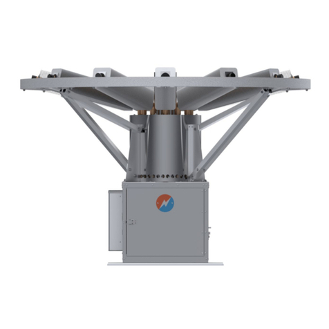
TABLE OF CONTENTS
4 Appendix ............................................................49
4.1 GasSpecications ...................................................49
4.2 TEGStartUpDataSheet .............................................50
4.3 SystemPerformanceLog .............................................52
II

List of Figures
Figure1 TEGDesign ........................................................3
Figure2 PhysicalDescription,1120TEG ........................................5
Figure3 ElectricalOutputCharacteristics ........................................7
Figure4 PowerVs.AmbientTemperature ........................................8
Figure5 TEGMounting .....................................................10
Figure6 MechanicalInspection ...............................................11
Figure7 RecommendedConnections ..........................................12
Figure8 ApplyingThreadSealant .............................................13
Figure9 ChangeinFuelPressureVs.Elevation ..................................16
Figure10 TEGStartUp ......................................................17
Figure11 VsetVs.Time.......................................................18
Figure12 VsetVs.SetUpPower. . . . . . . . . . . . . . . . . . . . . . . . . . . . . . . . . . . . . . . . . . . . . . . .20
Figure13 ChangeinVsetVs.AirShuttingSetting ..................................21
Figure14 FuelPressureVs.Vset ...............................................23
Figure15 TEGSubsystems ...................................................25
Figure16 PowerUnit ........................................................26
Figure17 AutoShutO......................................................27
Figure18 SchematicDiagram,1120TEG(sheet1of2).............................30
Figure19 SchematicDiagram,1120TEG(sheet2of2).............................31
Figure20 ElectronicsDiagram,1120TEG........................................32
Figure21 RemovingFuelSystem ..............................................35
Figure22 FuelRegulator .....................................................35
Figure23 1120TEGPartsIllustration ...........................................39
Figure24 IgnitorDetail .......................................................41
Figure25 BurnerParts .......................................................42
Figure26 FuelSystemParts ..................................................44
Figure27 ConduitAssemblyParts ..............................................45
Figure28 IgnitorHousingParts................................................46
Figure29 ElectronicsBox.....................................................47
Figure30 ElectronicsBoxLid..................................................48
III

IV

MODEL1120
HAZARDOUSAREAGENERATINGSYSTEM
DESIGNEDFOR
CLASSI,DIVISION2,GROUPD
T3OPERATION
SPECIFICATIONS
Output Voltage
Nominal 12-18VDC
24-30VDC
Power Output 100WattsMinimum
Special Features DigitalPanelMeter,LED,VoltageandCurrent
IntegralBlockingDiode
VoltageSensingAlarmwithdrycontacts
AutoShuto
SparkIgnition
AutoRe-ignition
Fuel Consumption NaturalGas:8.8m3perday,(311Sft3 perday)
Propane:11.4Lperday,(30USgalperday)
Inlet Fuel Supply Pressure Max172kPa(25psi)
Min69kPa(10psi)NaturalGas
Min103kPa(15psi)Propane
Dimensions
Width 61cm(24.0in.)withelectronicsboxclosed
92cm(36.0in.)withelectronicsboxopen
Depth 80cm(31.6in.)
Height 115cm(45.3in.)withdripcap
126cm(49.4in.)withrainshroud
Weight 123kg.(270lbs.)
Operating Temperature -20ºC(-4ºF)to+40ºC(105ºF)
Storage Temperature -65ºC(-85ºF)to+65ºC(149ºF)
V


Global Power Technologies
1120 - Class I, Division 2, Group D, T3
1 GENERAL
1.1 General Information
Thismanualprovidesinstallation,operationandmaintenanceinstructionsfortheGlobalPower
Technologies(GPT)Model1120ThermoelectricGeneratorSystem.
Special Customer Option: If the Generator System was ordered with specially engineered
options,theyarecompletelydescribedintheredSpecialCustomerOptionsectionoftheman-
ual.
1.2 DenitionofTerms
Tocorrectlyusethismanualthereadermustinterpretthemeaningofthefollowingwordsas
hereindened:
Thermoelectric Generator:Adevicethatproduceselectricalpowerthroughthedirectconver-
sionofheatenergytoelectricalenergy.
Power Unit:Thehermeticallysealedportionofthegeneratorthatcontainsthethermoelectric
materialsandthecoolingns.
TEG:Athermoelectricgenerator.
Matched Load:Aconditionofloadwhere:
a) theloadvoltageofthegeneratorisone-halfoftheopencircuitvoltage.
b) theloadresistanceisequaltotheinternalresistanceofthegenerator.
Optimum Load:Aconditionofloadwherethepoweroutputofthegeneratorismaximized.
Precision Load:Theprecisionresistorcontainedonthegeneratorthatprovidestheoptimum
loadcondition.ThevoltageacrosstheresistorisdenedasVsetandisusedtoanalyzegener-
atorelectricalperformance.
Power Conditioner:Abroadtermusedtodescribeanelectronicdeviceattachedtothegen-
eratoroutputthatconverts,adjusts,limitsorotherwiseconditionspower.
AutoShuto:The1120generatorisequippedwithathermocouplecontrolledsolenoidvalve
thatcanbemanuallyreset.Intheeventofextendedamefailurethethermocoupleoutputwill
bereducedsucientlytoreleasethesolenoidandstopfuelgasowtotheburner.
Converter:Aspecicelectronicdeviceattachedbetweenthegeneratorandloadthatconverts
onelevelofDCvoltagetoanother.
Limiter:Aspecicelectronicdeviceattachedacrossthegeneratoroutputthatlimitsthevolt-
agelevel.
1

Global Power Technologies
1120 - Class I, Division 2, Group D, T3
Generator System:Thesystemconsistingofthegeneratorincludingitsfactoryoptions,the
powerconditionerincludingitsfactoryoptions,andthespecialcustomeroptions.
Safe Operation, Operate Safely, Operating Safely:Thesearetermsusedtodescribethe
operationofthe1120GeneratingSystem,whenitsoperatingareaorzone,shouldsuddenlyor
graduallygohazardoustowardsorbeyondthelowerexplosivelimit(LEL).Thegeneratorwill
eitheroperateatreducedpowerorextinguishcompletelyduetolackofoxygen.Thegenerator
systemwillnot,eitherwhilerunningorattemptingtobeignited,ignitethesurroundinghazard-
ousatmosphere.Iftheoperatingareashouldclearwithinashortperiodoftimethegenerator
willattempttoreigniteitself.Seeshorttermautoignition.
Short Term Auto Ignition: The generators high voltage ignition system will automatically
comeontoreigniteitselfintheeventofaamefailureduetoeitherablowoutorshortdura-
tiongasfailure.Fuelgasmustbepresentandtheshutovalvemustnothaveoperatedfor
theautoreignitiontooccur.
Hazardous Area:(denitionperCanadianElectricalCode,Part1,Section18)
18-002Classication:Hazardouslocationsshallbeclassiedaccordingtothenatureofthe
hazard,asfollows:
a) ClassIlocationsarethoseinwhichammablegasesorvapoursareormaybesucient
toproduceexplosiveorignitiblemixtures;
b) ClassIIlocationsarethosewhicharehazardousbecauseofthepresenceofcombusti-
bleorelectricallyconductivedusts;
c) Class III locations are those which are hazardous because of the presence of easily
ignitiblebersoryings,butinwhichsuchbersoryingsarenotlikelytobeinsuspen-
sioninairinquantitiessucienttoproduceignitiblemixtures.
18-004DivisionofClassIlocations:ClassIlocationsshallbefurtherdividedintotwodivisions
asfollows:
a) Division1,comprisingClassIlocationsinwhich:
(i) Hazardous concentrations of ammable gases or vapours exist continuously,
intermittently,orperiodicallyundernormaloperatingconditions;or
(ii) Hazardousconcentrationsofammablegasesorvapoursmayexistfrequently
becauseofrepairormaintenanceoperationorbecauseofleakage;or
(iii) Equipmentisoperatedorprocessescarriedonofsuchnaturethatbreakdownor
faultyoperationthereofcouldresultinthereleaseofhazardousconcentrationsof
ammablegasesorvapoursandsimultaneousfailureofelectricalequipment;
b) Division2,comprisingClassIlocationsinwhich:
2

Global Power Technologies
1120 - Class I, Division 2, Group D, T3
(i) Flammablevolatileliquids,ammablegasesorvapoursarehandled,processed,
orused,butinwhichtheliquids,gases,orvapoursarenormallyconnedwithin
closedcontainersorclosedsystemsfromwhichtheycanescapeonlyasaresult
ofaccidentalruptureorbreakdownofthecontainersorsystemsortheabnormal
operationoftheequipmentbywhichtheliquidsorgasesarehandled,processed,
orusedor;
(ii) Hazardousconcentrationofgasesorvapoursarenormallypreventedbypositive
mechanicalventilation,butwhichmaybecomehazardousastheresultoffailure
orabnormaloperationoftheventilationequipmentor;
(iii) ThelocationisadjacenttoaClassI,Division1location,fromwhichahazardous
concentrationofgasesorvapourscouldbecommunicated,unlesssuchcommu-
nicationispreventedbyadequatepositivepressureventilationfromasourceof
cleanair,andeectivesafeguardsagainstventilationfailureareprovided.
c) GroupDincludespropane,methane,butane.
NOTE: Throughoutthis manualthe wordsGenerator,Thermoelectric Generator,TEGand
GeneratorSystemwillbeusedinterchangeably.
1.3 Theory of Operation
A TEG produces electrical power through
the direct conversion of heat energy into
electricalenergy.Itoperatesonthesame
principle as the thermocouples that are
used for measuring temperatures and in
safetyshutocontrolsforgaswater heat-
ers, home furnaces, etc.. However, the
TEG utilizes semiconducting thermoelec-
tricmaterialsthat are much more ecient
and thus permit practical thermoelectric
power sources. A thermocouple consists
oftwodissimilar materials (usually in wire
form) which are joined together at one
end. If this junction is heatedto a higher
temperaturethantheotherendofthewire,
a voltage will exist across the cooler end.
Further,electricalpowerwillbedeliveredto
aloadplacedinthecircuit.Thisprocesswillcontinueprovidedthatthetemperaturedierence
ismaintained.ATEGisasystemwhichprovidesthemeanstomaintaintheserequiredcon-
ditions.
Figure1illustrateshowthisisaccomplishedinthemodel1120TEG.Athermocoupleisformed
byaPtypeandanNtypethermoelectricelementjoinedtogetherelectricallybyahotjunction
electrode.Adjacentthermocouplesarejoinedtogetherelectricallybycoldjunctionelectrodes.
Eightythermocouples,eachproducing84mVareconnectedinseriessothepowerunitproduc-
es120Wattsat6.7Voltsand18Amperes.
Figure1TEGDesign
3

Global Power Technologies
1120 - Class I, Division 2, Group D, T3
Thehotjunctionofthethermocouplesismaintainedatahightemperature(538ºCor1000ºF)by
aburnerwhichoperatesongaseousfuelssuchaspropaneornaturalgas.Thecoldjunctionof
thethermocouplesismaintainedatalowertemperature(163ºCor325ºF)byanarrayofcooling
nswhichtransfertheheattoambientairbynaturalconvection.Thethermocouplesarecon-
tainedinahermeticallysealedenclosurebecausetheyareadverselyaectedwhenexposedto
airatoperatingtemperatures.Theyaresurroundedbythermalinsulationtominimizeheatloss.
Maximumpowerisdeliveredtotheloadwhen:(a)theloadvoltageisone-halfoftheopencircuit
voltageand(b)theloadresistanceisequaltotheinternalresistance.Thisconditioniscalled
thematched-loadpower(alsomaximumeciency)whentheloadvoltageisslightlyhigherthan
one-half(approx.55%)oftheopencircuitvoltage.
TheTEGissuppliedwithaprecisionloadresistorthatprovidesaknownload.Thisresistor
isusedbothinadjustingtheTEGforproperoperationandinevaluatingitsperformance.The
fuelowtotheburnerisadjustedsothatthepropervoltageexistsacrossthisprecisionresistor.
Atthis condition the TEG isoperatingattheintended junction temperature and isdelivering
maximumpower.
The TEG is supplied with a protective device which prevents its output voltage from rising
beyond11.4Volts.Thisisrequiredbecauseunderextendedopencircuit(orslightlyloaded)
conditionsthehotjunctiontemperaturecouldincreasebeyondthesafeoperatingrange.
The burner operates at moderate pressures from 28 to 70 kPa (4 to 10 psi). The gas is
expandedthroughanoriceandthenowsthroughaventuriwhereitdrawsinairneededfor
combustion.Thefuelowiscontrolledbyapressureregulatorandisadjustedbytheoperator
toobtainthedesiredpoweroutput.
Insummary,theTEGproduceselectricalpowerwhenatemperaturedierenceismaintained
betweenthehotandcoldjunctionsofthethermoelectricmaterials.Thetemperaturedierence,
andthereforetheamountofpowerproduced,dependsontherateatwhichfuelissuppliedto
theburner.TheoperationoftheTEGissimplythecontrolofthefuelpressuretotheburner
whichresultsinthedesiredpoweroutput.
1.4 Physical Description
Figure2showsthegeneratorinitsnormaloperatingposition.
4

Global Power Technologies
1120 - Class I, Division 2, Group D, T3
1120 TEG w/ Drip Cap
1120 TEG w/ Rain Shroud
Figure 2 PhysicalDescription
5

Global Power Technologies
1120 - Class I, Division 2, Group D, T3
1.5 Electrical Output Characteristics
Figure3showstheelectricaloutputcharacteristicsoftheModel1120powerunit,whichgives
thepower,currentandvoltageasafunctionoftheloadresistance.TheTEGwilloperateat
anyloadconditionfromshortcircuittoopencircuit.Observethatthepowergoesthrougha
broadmaximumbetween0.3and0.5ohms.Ratedpower(120Watts)canbeobtainedonly
iftheloadresistanceiswithinthisrange.Thegraphisusefulindeterminingpower,current
andvoltageatvariouscustomerloadconditions.Refertothegraphandconsiderthefollowing
example:
1) You are installing a Model 1120 TEG at a gas wellhead to cathodically protect the
well-casingfromcorrosion.
2) Youhavemeasuredanddeterminedyourtotalgroundbedresistancetobe1.0ohm.
3) Find1.0ohmonthehorizontalaxis.
4) Readverticallyuntilintersectingthepower,current,andvoltagecurves.
5) Readhorizontallytotheverticalaxistodeterminethevaluesofpower,currentandvolt-
age.
6) Whichare106Watts,10.2Ampsand10.3Volts.
1.6 AmbientTemperatureEects
TheelectricaloutputoftheTEGisdependentonambienttemperatureasshowninFigure4.
Observethatthepowerdecreasesasambienttemperatureincreases.
Statement of Rated Power
1) ThePowerUnitproduces120Wattswhenoperatedatanambienttemperatureof20ºC.
2) Withthefuelowheldconstant,thepowerchangesatarateof0.288%perºC(0.16%per
ºF)oftemperaturechange.
3) TheTEGcanbeoperatedatratedpowertoamaximumambienttemperatureof40ºC
(105ºF).ConsultGPTifambienttemperaturesexceed40ºC.
1.7 Rated Power
TheTEGcanbeadjustedforratedpoweratanambienttemperaturebyusingtheratedpower
curveasshowninFigure4.Considerthefollowingexample:
1) Thepresentsitetemperatureis40ºC.
2) Find40ºConthehorizontalaxis.
3) Readverticallyuntilintersectingtheratedpowercurve.
4) Readhorizontallytotheverticalaxistondtheset-uppower.
5) Whichis114watts.
6

Global Power Technologies
1120 - Class I, Division 2, Group D, T3
Figure 3 PowerUnitElectricalOutputCharacteristics@20°
7

Global Power Technologies
1120 - Class I, Division 2, Group D, T3
Figure 4 GrossPowerfrom1120PowerUnitVsAmbientTemperature
8

Global Power Technologies
1120 - Class I, Division 2, Group D, T3
1.8 Fuel Consumption
ThefuelconsumptionoftheTEGoperatedatratedpowerisshownbelow.TheTEGcanbe
operatedatlessthanratedpower,downto75%or90Watts.
1.9 Boiling Temperature of Fuel
Boilingpointofliqueedfuelsatatmosphericpressureare:
methane -166.5ºC(-258.7ºF)
propane -42.1ºC(-43.7ºF)
butane -0.5ºC(+31.1ºF)
1.10 Installation
Thisgeneratormustbeinstalledbyqualiedpersonnelinaccordancewithinternationaland/or
localelectricalcodes.
CarefullyunpacktheTEGfromshippingcontainer.RetaintheshippingcontaineruntiltheTEG
isoperational.
Identifyandlocatethefollowingitemsfromtheshippingcontainer:
A. GeneratorSystemComplete.
B. CustomerAssyKit.
MounttheTEGonageneratorstand,ifastandhasnotbeenprepared,aeldprovenmount-
ingarrangement is showninFigure 5. Ensurethat the TEGismounted in accordancewith
followingnotes:
A. TheTEGmustbemountedwiththenductinaverticalposition.
B. Theairowthroughthecoolingnsmustnotbeobstructed.
C. TheTEG should bemountedata height sucienttoprevent direct ooding orheavy
snowfallfrominterferingwiththeowofcoolingorintakeair.
D. Whenthegeneratorisinstallednearabuilding,eldexperiencehasshownthatthebest
locationsareontherooforonthewindwardside,withaminimumdistanceof3.0meters
(10feet)fromthebuilding.BesurethattheTEGlocationrelativetobuildingsandfuel
containersareinaccordancewithlocalregulations.
FUELCONSUMPTION
ATRATEDPOWER
PROPANE
C3H8
BUTANE
C4H10
NATURALGAS
METHANECH4
LB/HR 0.54 0.54 -
GAL/HR 0.13 0.13 -
KG/HR 0.25 0.25 -
L/HR 0.48 0.42 -
CUFT/HR 4.70 3.52 13.0
CUM/HR 0.133 0.099 0.368
9

Global Power Technologies
1120 - Class I, Division 2, Group D, T3
Removetherainshroud(iftheTEGc/warainshroud),thenductfrontcover,thedripcap(if
theTEGc/wadripcap).WithasuitableliftingdeviceandtheLiftingLug(showninFigure6),
gentlyliftandmovetheTEGtoplace.WhentheTEGhasbeenmountedonthestand,proceed
withacompletemechanicalinspection.
1.11 Mechanical Inspection (see Figure 6)
Ensure the exhaust ame arrestor assembly is screwed tight to the exhaust stack, and all
screwsontheamearrestorassemblyaretight.Visuallyinspecttheamearrestorelementby
lookingdowntheexhaustpipetoensurethatthereisnovisualdamageorfractures.Replace
thedripcap(iftheTEGc/wadripcap),thenductfrontcover,therainshroud(iftheTEGc/w
arainshroud).
Openthefrontdoorsofthecabinetandlocatetheburnermountingbolts,tightenthecapnuts,
andlocatetheairintakeamearrestorassemblies.Ensurethattheyaretightlysecured.
LocatetheIgniterhousingassembly,removethecapandvisuallyinspecttheignitorconnec-
tions, re-installing the cap securely. Check that all conduit connections are secure and the
mountingsaretight.
Locatethefuelsystemassemblyandensurethatalltheconnectionsaretight.
Check that all hardware and mountings are secure and tighten as necessary. When the
mechanicalinspectioniscomplete,proceedtoelectricalconnection.
Figure 5 TEGMounting
10

Global Power Technologies
1120 - Class I, Division 2, Group D, T3
Figure 6MechanicalInspection,
•
•
•
•
• •
•
©
'v•
©
_ ,_
1120 TEG w/ Drip Cap
1120 TEG w/ Rain Shroud
11

Global Power Technologies
1120 - Class I, Division 2, Group D, T3
1.12 Electrical Connection
NOTE: ThisTEGincorporatesahighvoltageignitionsystemthatoperatesfromaninternal
2Voltbattery.ThisbatteryischargedbytheTEG.Disconnectoneendofthe2Volt
ignitor battery and proceed with connection of the customer wiring (see Figure 7).
Proceedtofuelconnection.
Ensurethatcircuitbreakersordisconnectsareusedattheloadendofthewiringandthatthe
circuitisopenpriortoconnectiontotheTEG(seeFigure7).Ifthe2Voltbatteryandthedis-
connectsarenotopenthentheignitionsystemisstillliveandcouldcauseanexplosion.
Provision has been made in the electronics housing for two 3/4” NPT rigid conduit entries.
Sealingofthesettingsmustbeusedtomaintainthesystemintegrity.Foraccesstotheelec-
tronicsassembly,removethe twenty 3/8-16 bolts installed in the lid and swing the lid open.
Terminal blocks have been factory installed for customer connection. TB2-2 is +24 Volts,
TB2-3is-24Volts.ThevoltagesensingrelayterminalsarelocatedontheLimiterConverter
boardmountedonthelid.
1.13 Fuel Supply Connection
AlthoughtheTEGfuelregulatorincorporatesaliquidtrapand40-50micronstainlesssteellter,
thegeneratorsystemhasbeendesignedtooperateonsalesorinstrumentqualityfuel.Dueto
sitespecicfuelcharacteristics,ensurethatnecessarypre-ltrationhasbeeninstalledpriorto
connectiontoTEGfuellines.
Figure 7RecommendedConnections
12
Table of contents
Other Global Portable Generator manuals

Global
Global 5120 User manual

Global
Global Sentinel User manual

Global
Global MX PrimeGen User manual

Global
Global 5030 User manual

Global
Global P-5100 User manual

Global
Global S-8500 User manual

Global
Global MX PrimeGen Installation and user guide

Global
Global 8550-RU User manual

Global
Global 716174 User manual

Global
Global 8550-SD User manual
Popular Portable Generator manuals by other brands

Team Orion
Team Orion dDrive instruction manual

Peak Gas Generation
Peak Gas Generation i-Flow 6000 Series user manual

Clas Ohlson
Clas Ohlson Cocraft 40-9411 Original instructions

Stanley
Stanley HP Twin 8 user manual

Generac Power Systems
Generac Power Systems GP8000E owner's manual

Makita
Makita EG301A Instructions for use