Ambient WS-3000 User manual

Version 1.1 ©Copyright 2016, Ambient LLC. All Rights Reserved. Page 1
Ambient Weather WS-3000 Thermo-Hygrometer, Dew
Point, Heat Index Wireless Monitor with Graphing,
Alarming, and Radio Controlled Clock User Manual
Table of Contents
1Introduction.....................................................................................................................................3
2Getting Started ................................................................................................................................3
2.1 Parts List.................................................................................................................................3
2.2 Recommend Tools..................................................................................................................3
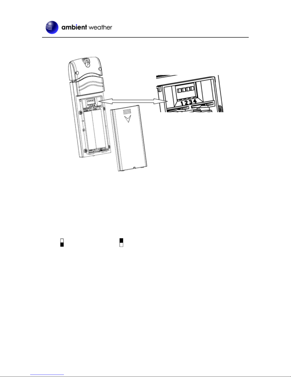
2.3 Thermo-Hygrometer Sensor Set Up.......................................................................................3
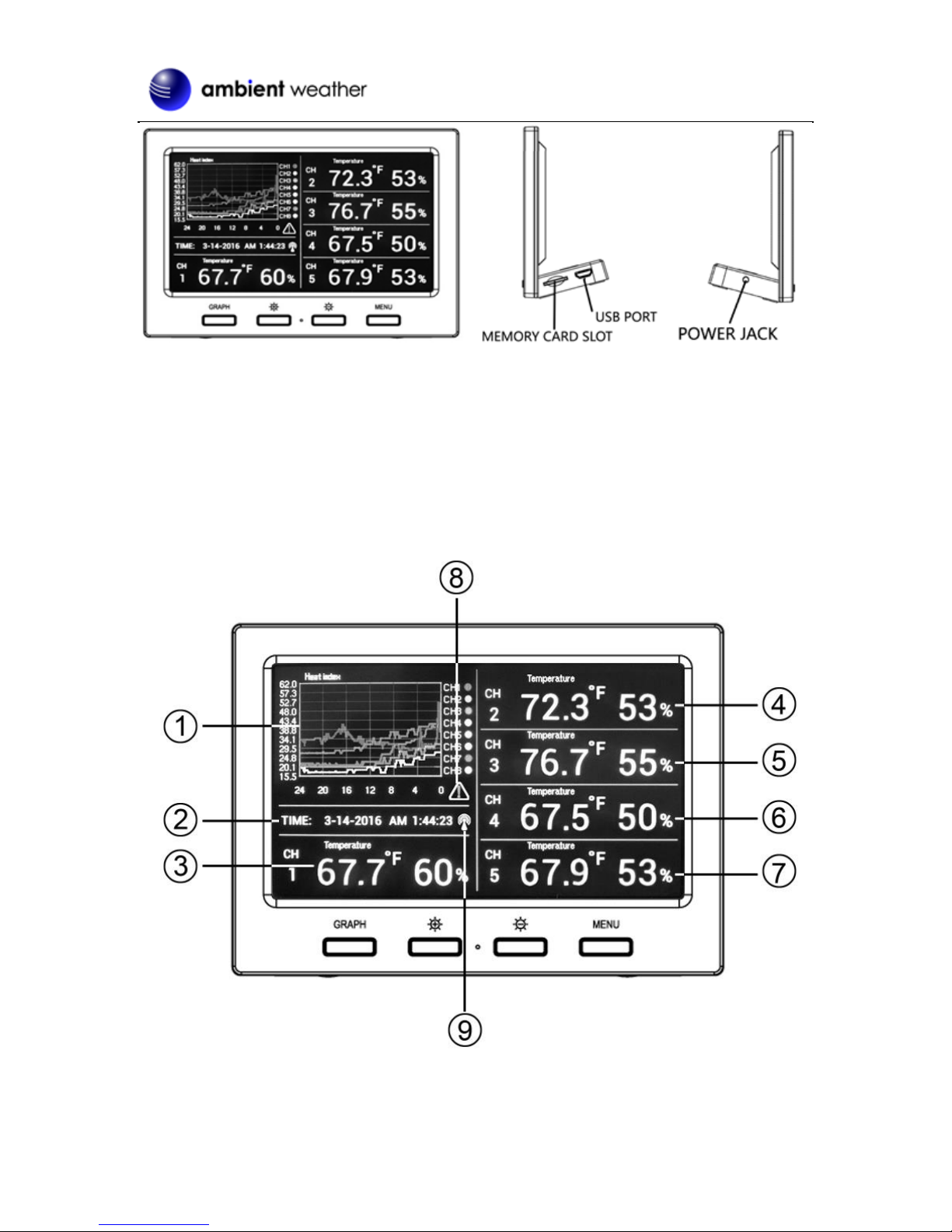
2.4 Display Console Set Up .........................................................................................................5
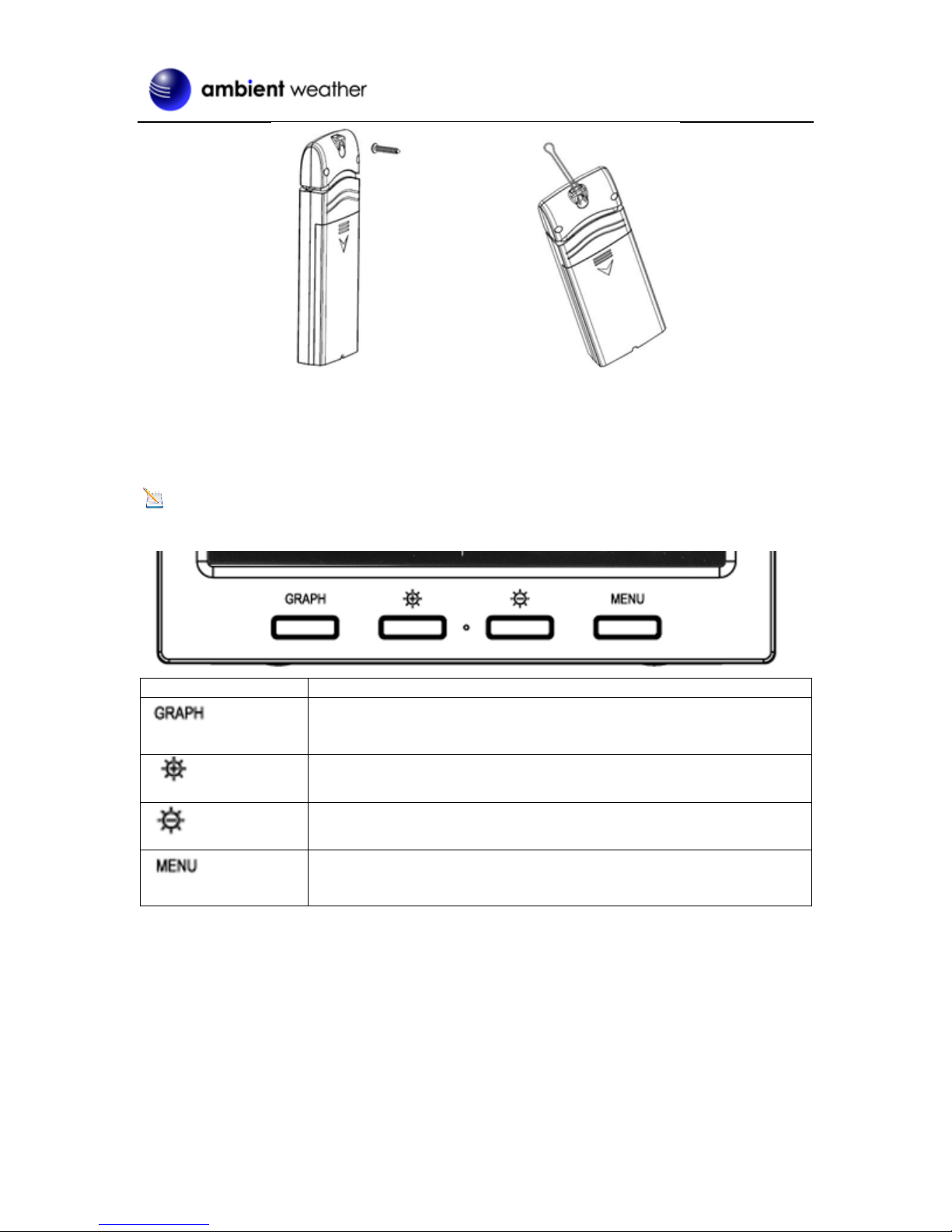
2.4.1 Display Console Layout.........................................................................................................6
2.4.2 Sensor Operation Verification............................................................................................7
3Remote Sensor Installation .............................................................................................................7
4Console Operation...........................................................................................................................8
4.1 Setup Mode ............................................................................................................................8
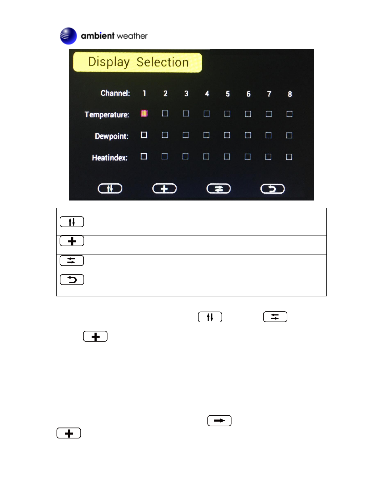
4.1.1 Display Selection ...............................................................................................................9
4.1.2 Graph Time ......................................................................................................................10
4.1.3 Time Format.....................................................................................................................11
4.1.4 Date Format...................................................................................................................... 11
4.1.5 Date and Time Format...................................................................................................... 11
4.1.6 Temperature Units of Measure.........................................................................................12
4.2 Calibration............................................................................................................................12
4.2.1 Notes about Calibration....................................................................................................14
4.2.2 Humidity Calibration Methods.........................................................................................14
4.2.3 Temperature Calibration Methods........................................................................................15
4.3 Min / Max andAlarm Mode.................................................................................................15
4.3.1 Min / Max.........................................................................................................................15
4.3.2 Alarms..............................................................................................................................16
4.4 Factory Settings....................................................................................................................19
4.4.1 Factory Reset....................................................................................................................19
4.4.2 Clear Max/Min Values .....................................................................................................20
4.4.3 Re-register Sensors...........................................................................................................20
4.4.4 About................................................................................................................................20
4.4.5 Language..........................................................................................................................21
4.4.6 Back Light........................................................................................................................21
5Other Features...............................................................................................................................22
5.1 Radio Controlled Clock (RCC)............................................................................................22
5.2 SD Card Export and Firmware Updates...............................................................................22
5.2.1 SD Data Export................................................................................................................23
5.2.2 Back Up Graph Data........................................................................................................23
5.2.3 Firmware Updates............................................................................................................23
5.3 PC Software..........................................................................................................................24
5.3.1 Getting Started .................................................................................................................24
5.3.2 Time, Date and Display Setup..........................................................................................25

Version 1.1 ©Copyright 2016, Ambient LLC. All Rights Reserved. Page 2
5.3.3 Alarm Settings..................................................................................................................26
5.3.4 Calibration........................................................................................................................27
5.3.5 SDCard File......................................................................................................................27
6Best Practices for Wireless Communication.................................................................................29
7Glossary of Terms.........................................................................................................................30
8Accessories ...................................................................................................................................30
9Specifications................................................................................................................................30
9.1 Wireless Specifications ........................................................................................................30
9.2 Measurement Specifications.................................................................................................30
9.3 Power Consumption.............................................................................................................30
10 Troubleshooting Guide.............................................................................................................31
11 Liability Disclaimer..................................................................................................................32
12 FCC Statement..........................................................................................................................32
13 Warranty Information ...............................................................................................................33

Version 1.1 ©Copyright 2016, Ambient LLC. All Rights Reserved. Page 3
1Introduction
Thank you for your purchase of the Ambient Weather WS-3000 Thermo-Hygrometer, Dew Point, Heat
Index Wireless Monitor with Graphing, Alarming, and Radio Controlled Clock. The following user
guide provides step by step instructions for installation, operation and troubleshooting. To download
the latest manual and additional troubleshooting tips, please visit:
http://ambientweather.wikispaces.com/ws3000
2Getting Started
Note: The power up sequence must be performed in the order shown in this section (insert
batteries in the remote transmitter(s) first, Display Console second).
The WS-3000 weather station consists of a display console (receiver), and up to 5 thermo-hygrometers
(remote transmitters), based on your order configuration.
2.1Parts List
QTY
Item
1
Display Console
Frame Dimensions (LxHxW): 4.5 x 3.75 x 1.5 in
LCD Dimensions (LxW): 3.75 x 2.25”
*
Thermo-hygrometer transmitter (WH31)
Dimensions (LxHxW): 4.75” x 1.5” x 0.6”
1
USB Cable for PC Connection
* 1,2,3,4, or 5, based on your order configuration.
2.2Recommend Tools
Hammer and nail for hanging remote thermo-hygrometer transmitter(s).
2.3Thermo-Hygrometer Sensor Set Up
Note: Do not use rechargeable batteries. We recommend fresh alkaline batteries for outdoor
temperature ranges between -4 °F and 140 °F and fresh lithium batteries for outdoor temperature
ranges between -40 °F and 140 °F.

Version 1.1 ©Copyright 2016, Ambient LLC. All Rights Reserved. Page 4
1. Remove the battery door on the back of the transmitter(s) by sliding down the battery door, as
shown in Figure 1 .
Figure 1
2. BEFORE inserting the batteries, locate the dip switches on the inside cover of the lid of the
transmitter.
3. Channel Number: The WS-3000 supports up to eight transmitters, and includes three
transmitters. To set each channel number (the default is Channel 1), change Dip Switches 1, 2
and 3, as referenced in Figure 2.
4. Temperature Units of Measure: To change the transmitter display units of measure (°F
vs. °C), change Dip Switch 4, as referenced in Figure 2.
Switch in down position. Switch in up position.

Version 1.1 ©Copyright 2016, Ambient LLC. All Rights Reserved. Page 5
Figure 2
5. Insert two AA batteries.
6. Verify the correct channel number (CH) and temperature units of measure (°F vs. °C) are on
the display, as shown in Figure 3.
Figure 3
(1) temperature
(2) temperature units (°F vs. °C)
(3) channel number
(4) relative humidity
7. Close the battery door.
8. Repeat for the additional remote transmitters, verifying each remote is on a different channel.
2.4Display Console Set Up
1. Move the transmitters(s) about 5 to 10’ away from the display console (if the transmitters are
too close, they may not be received by the display console). With multiple transmitters, make
sure all transmitters are powered up and displaying different channels on the display.
2. Connect the console to AC power with the includedAC adapter (Figure 4).

Version 1.1 ©Copyright 2016, Ambient LLC. All Rights Reserved. Page 6
Figure 4
If the remotes do not update, please reference the troubleshooting guide in Section 10.
2.4.1 Display Console Layout
Figure 5

Version 1.1 ©Copyright 2016, Ambient LLC. All Rights Reserved. Page 7
No
Description
No
Description
1
Graph for Temperature/Dew point/heat
index/humidity of Indoor/outdoor
sensors.
6
Outdoor Temperature/Dew point/heat
index/humidity for channel 4 and other
channels defined to be displayed in
CH4 area.
2
Date and time.
7
Outdoor Temperature/Dew point/heat
index/humidity for channel 5 and other
channels defined to be displayed in
CH5 area.
3
Outdoor Temperature/Dew point/heat
index/humidity for channel 1 and other
channels defined to be displayed in CH1
area.
8
Alarm Icon.
4
Outdoor Temperature/Dew point/heat
index/humidity for channel 2 and other
channels defined to be displayed in CH2
area.
9
Radio Controlled Clock reception icon.
5
Outdoor Temperature/Dew point/heat
index/humidity for channel 3 and other
channels defined to be displayed in CH3
area.
2.4.2 Sensor Operation Verification
Verify the humidity sensors match closely with all of the sensors in the same location (about 5 to 10’
apart). The sensors should agree within 10% (the accuracy is ± 5%). Allow about 30 minutes for all
sensors to stabilize. The humidity can be adjusted or calibrated later to match each other a known
source.
Verify the temperature sensors match closely with all of the sensors in the same location (about 5 to
10’ apart). The sensors should be within 4°F (the accuracy is ± 2°F). Allow about 30 minutes for all
sensors to stabilize. The temperature can be adjusted or calibrated later to match each other or a
known source.
3Remote Sensor Installation
If you mount one or more of the sensors outside, it is recommended you mount the sensor in a shaded
area. Direct sunlight and radiant heat sources will result in inaccurate temperature readings. Although
the sensors are water resistant, it is best to mount in a well-protected area, such as under an eve. Use a
screw to affix the remote sensor to the wall, as shown in Figure 6.
Alternately, you can hang the sensor with fishing wire or a string. This insures the sensor does not
come into contact with any radiant heat source.

Version 1.1 ©Copyright 2016, Ambient LLC. All Rights Reserved. Page 8
Figure 6
4Console Operation
Note: The console has four buttons for easy operation: Graph, Brightness +, Brightness –and
Menu.
Icon
Description
Graph key
Switch to display graph of Temperature/Dew point/heat index/humidity
for all sensors
Brightness control key
Press this key to increase the brightness
Brightness control key
Press this key to decrease the brightness
Menu Key
Press this key to enter menu and scroll to different modes
Figure 7
4.1 Setup Mode
In the Normal mode, press the MENU key once to enter Setup Mode.

Version 1.1 ©Copyright 2016, Ambient LLC. All Rights Reserved. Page 9
Icon
Description
Scroll right key
Press this key to scroll down/right. .
Selection key
Press this key to select and enter the option.
Scroll left key
Press this key to scroll up/left.
Mode key
Press this key to enter to next mode
Figure 8
4.1.1 Display Selection
You can customize or even scroll between various parameters within each one of the Channel areas.
Scroll to selected channel area (1-5), and press the plus key to modify the home
display screen area:

Version 1.1 ©Copyright 2016, Ambient LLC. All Rights Reserved. Page 10
Icon
Description
Scroll up/down key
Press this key to scroll down/up. .
Selection key
Press this key to select and enter the option.
Scroll right/left key
Press this key to scroll right/left.
Return key
Press this key to back to Setup main menu.
Figure 9
To modify the display parameter, press the up/down and left/right keys to move
the blue cursor to a sensor channel number (1-8) and parameter (temperature, dew point, heat index).
Press the key to display this channel and parameter in the selected area on the main screen.
For example, if you wish to display Channel 1 Dew Point in the CH Area 1, highlight the Channel 1
Dewpoint field.
If you wish to toggle both channel 1 temperature and channel 1 dew point, highlight both the Channel
1 Temperature and Channel 1 Dew Point (reference Figure 9),, and the screen will toggle between the
channel 1 temperature and dew point on the main screen once every 3 seconds.
4.1.2 Graph Time
To change the Graph Time on the main display, scroll to the Graph Time, and select the
key to change between 12, 24, 48 and 72 hours.

Version 1.1 ©Copyright 2016, Ambient LLC. All Rights Reserved. Page 11
4.1.3 Time Format
To change the Time Format on the main display, scroll to the Time Format, and select the
key to change between AM h:mm:ss, hh:mm:ss AM (12 hour time format) and h:mm:ss (24
hour time format)
4.1.4 Date Format
To change the Date Format on the main display, scroll to the Date Format, and select the
key to change between MM-DD-YYYY, DD-MM-YYYY and YYYY-MM-DD.
4.1.5 Date and Time Format
Figure 10
The console receives the radio controlled time signal from any one of the wireless sensors. The time
and date will set automatically, and adjust for Daylight Savings Time (DST). To work properly, you
must enter the time zone and DST. You can also manually enter the time.
To manually change the time and data settings, scroll to the field you wish to change, and
press the or key to adjust up or down.
Turn ON the DST setting, unless you reside in Arizona or Hawaii, which do not observe Daylight
Savings Time.
Adjust your time zone according to the table below:
Hours from
GMT
Time Zone
Cities
-12
IDLW: International Date Line West
---
-11
NT: Nome
Nome, AK

Version 1.1 ©Copyright 2016, Ambient LLC. All Rights Reserved. Page 12
Hours from
GMT
Time Zone
Cities
-10
AHST: Alaska-Hawaii Standard
CAT: Central Alaska
HST: Hawaii Standard
Honolulu, HI
-9
YST: Yukon Standard
Yukon Territory
-8
PST: Pacific Standard
Los Angeles, CA, USA
-7
MST: Mountain Standard
Denver, CO, USA
-6
CST: Central Standard
Chicago, IL, USA
-5
EST: Eastern Standard
New York, NY, USA
-4
AST: Atlantic Standard
Caracas
-3
---
São Paulo, Brazil
-2
AT: Azores
Azores, Cape Verde Islands
-1
WAT: West Africa
---
0
GMT: Greenwich Mean
WET: Western European
London, England
1
CET: Central European
Paris, France
2
EET: Eastern European
Athens, Greece
3
BT: Baghdad
Moscow, Russia
4
---
Abu Dhabi, UAE
5
---
Tashkent
6
---
Astana
7
---
Bangkok
8
CCT: China Coast
Bejing
9
JST: Japan Standard
Tokyo
10
GST: Guam Standard
Sydney
11
---
Magadan
12
IDLE: International Date Line East
NZST: New Zealand Standard
Wellington, New Zealand
Figure 11
4.1.6 Temperature Units of Measure
To change the temperature units of measure, scroll to the Temperature Units field, and
press the key to toggle between °F and °C.
4.2 Calibration
To enter the calibration mode, press the MENU key twice.

Version 1.1 ©Copyright 2016, Ambient LLC. All Rights Reserved. Page 13
Figure 12
Icon
Description
Scroll down/right key
Press this key to scroll down/right. .
Selection/value increase key
Press this key to select parameter and enter the calibration
interface. Increase the value during calibration.
Value Decrease key
Decrease the value during calibration.
Scroll up/left key
Press this key to scroll up/left.
Mode key
Press this key to enter to next mode
Return Key
Back to main menu of calibration mode.
Resume Key
Cancel the calibration and resume.
Figure 13
Scroll to the temperature or humidity field you wish to calibrate, press the key
to perform the calibration, and press the or key to match your calibration source.

Version 1.1 ©Copyright 2016, Ambient LLC. All Rights Reserved. Page 14
Figure 14
4.2.1 Notes about Calibration
Note: The calibrated value can only be adjusted on the console. The remote sensor(s) always
displays the un-calibrated or measured value.
Note: The measured humidity range is between 10 and 99%. Humidity cannot be accurately
measured outside of this range. Thus, the humidity cannot be calibrated below 10% or above 99%.
The purpose of calibration is to fine tune or correct for any sensor error associated with the devices
margin of error. The measurement can be adjusted from the console to calibrate to a known source.
Calibration is only useful if you have a known calibrated source you can compare it against, and is
optional. This section discusses practices, procedures and sources for sensor calibration to reduce
manufacturing and degradation errors. Do not compare your readings obtained from sources such as
the internet, radio, television or newspapers. They are in a different location and typically update once
per hour.
The purpose of your weather station is to measure conditions of your surroundings, which vary
significantly from location to location.
4.2.2 Humidity Calibration Methods
Official stations recalibrate or replace humidity sensors on a yearly basis. Due to manufacturing
tolerances, the humidity is accurate to ± 5%. To improve this accuracy, the indoor and outdoor
humidity can be calibrated using an accurate source, such as a sling psychrometer or one step
humidpak calibration kits available at AmbientWeather.com.

Version 1.1 ©Copyright 2016, Ambient LLC. All Rights Reserved. Page 15
4.2.3 Temperature Calibration Methods
Temperature errors can occur when a sensor is placed too close to a heat source (such as a building
structure, the ground or trees).
To calibrate temperature, we recommend a mercury or red spirit (fluid) thermometer. Bi-metal (dial)
and other digital thermometers are not a good source and have their own margin of error. Using a local
weather station in your area is also a poor source due to changes in location, timing (airport weather
stations are only updated once per hour) and possible calibration errors (many official weather stations
are not properly installed and calibrated).
Place the sensor in a shaded, controlled environment next to the fluid thermometer, and allow the
sensor to stabilize for 48 hours. Compare this temperature to the fluid thermometer and adjust the
console to match the fluid thermometer.
4.3 Min / Max and Alarm Mode
In the Normal mode, press the MENU key three times to enter Min / Max and Alarm Mode.
4.3.1 Min / Max
Icon
Description
Scroll down/right key
Press this key to scroll down/right. .
Selection/value increase key
Press this key to select parameter to check according max/min
records. Switch on/off alarms and increase the value during alarm
setup.

Version 1.1 ©Copyright 2016, Ambient LLC. All Rights Reserved. Page 16
Value Decrease key
Decrease the value during alarm setup.
Scroll up/left key
Press this key to scroll up/left.
Mode key
Press this key to enter to next mode
Return Key
Back to main menu of calibration mode.
Resume Key
Cancel the calibration and resume.
Figure 15
Scroll to the temperature, humidity, dew point or heat index min/max field you wish to
view, and press the key. Note that dashes (--.-) will be displayed for sensors that are not
programmed for your system.
Figure 16
To clear all of the min and max values, refer to Section 4.4.2 for details.
4.3.2 Alarms
You can set a high and low temperature and humidity alarm on Channels 1-8.
If the measured value is greater than the high alarm, an audible alert will sound and the alarm icon
will flash on the alarm panel, and the alarm icon will appear on the main panel.

Version 1.1 ©Copyright 2016, Ambient LLC. All Rights Reserved. Page 17
If the measured value is less than the high alarm, an audible alert will sound and the alarm icon
will flash on the alarm panel, and the alarm icon will appear on the main panel.
When an alarm has been triggered, the alarm will sound for 120 second and the corresponding alarm
icon will flash until the alarm condition is no longer met. Press any key to silence the alarm.
The alarm icon is color coded, and will flash as shown in Figure 17 if one or more alarms are
triggered.
Alarm Type
Color
HighAlarm
Red –grey - red
Low alarm
Blue –grey - blue
High alarm & Low alarm both activated
Red –grey –blue –grey –red
Beep alarm stop
grey
Figure 17
Scroll to the Humidity or Temperature Alarm On/Off switch, and press the key
to toggle the Humidity or TemperatureAlarm On or Off.
Scroll to the Humidity Alarm or Temperature Alarm field, and press the key to
display the alarm programming panel, as shown in Figure 18.
Note: The alarm must be turned On to program the alarm settings.
Referring to Figure 18, scroll to the channel and alarm limit, and press the or
key to adjust the alarm limit up or down. Scroll to the alarm field and press the
key to turn the alarm bell on our off to activate the alarm.

Version 1.1 ©Copyright 2016, Ambient LLC. All Rights Reserved. Page 18

Version 1.1 ©Copyright 2016, Ambient LLC. All Rights Reserved. Page 19
Icon
Description
Scroll down/right key
Press this key to scroll down/right. .
Selection/value increase key
Press this key to select parameter to set alarm thresholds and turn
on the alarm icon. Red alarm icon is high alarm. Blue one is low
alarm.
Value Decrease key
Decrease the value during alarm setup.
Scroll up/left key
Press this key to scroll up/left.
Mode key
Press this key to back to main menu or enter to next mode
Return Key
Back to main menu of alarm menu.
Figure 18
4.4 Factory Settings
To enter the Factory mode, press the MENU key four times.
Figure 19
4.4.1 Factory Reset
To restore to factory default, scroll to the Factory Reset field and press to clear
all settings and restore to factory default.

Version 1.1 ©Copyright 2016, Ambient LLC. All Rights Reserved. Page 20
4.4.2 Clear Max/Min Values
To clear all of the max and min values, scroll to the Clear Max/Min field and press
to clear all of the stored max and min values.
Figure 20
4.4.3 Re-register Sensors
If sensor communication is lost with a specific sensor, you can re-acquire.
Scroll to the re-register sensors field, and press to view the re-register panel.
Scroll the sensor you wish to register, and press to re-acquire this sensor. Press the
button to highlight Yes and press to confirm.
4.4.4 About
Scroll to the About field, and press to view to view the hardware and firmware
version.
Table of contents
Other Ambient Weather Station manuals
Popular Weather Station manuals by other brands

Hyundai
Hyundai WS 2244 instruction manual

Oregon Scientific
Oregon Scientific WMR300 user manual

Ambient Weather
Ambient Weather WS-GL026 user manual

Golze Engineering
Golze Engineering ADL120 Firmware update manual

Ventus
Ventus W157 owner's manual

Explore Scientific
Explore Scientific WSH4003 instruction manual