AMBISONICLANDSCAPESATELLITESPEAKER
4 5
3B. LSR60
LSR6 / LSR6-70V Specifications
10.375
1/2-NPT (Steel)
8.75
6.64
AVERAGE RESPONSE: Within the listening window
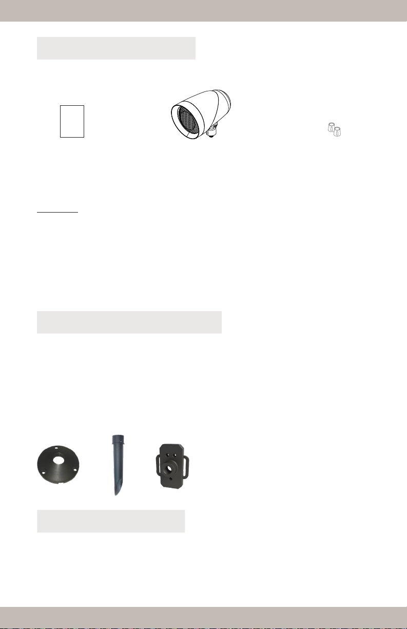
Ribbon equipped outdoor/landscape satellite loudspeaker
All-weather 5.25” glass fiber cone woofer, 2.8” planar magnetic ribbon driver
95hz - 20khz (-10db) 125hz - 20khz (+/- 3db)
110 degree horizontal / 75 degree vertical
Rated Impedance / Transformer
Model LSR6-8Ω / Model LSR6-70V-75W
24” x 14awg pigtail with water proof wire-nuts
Dimensions, (H x W x L) inches (mm)
8.75” (222.0mm) x 6.64” (168.5mm) x 10.375” (263.3mm)
LSR6 / LSR6-70V Specifications
10.375
1/2-NPT (Steel)
8.75
6.64
AVERAGE RESPONSE: Within the listening window
Ribbon equipped outdoor/landscape satellite loudspeaker
All-weather 5.25” glass fiber cone woofer, 2.8” planar magnetic ribbon driver
95hz - 20khz (-10db) 125hz - 20khz (+/- 3db)
110 degree horizontal / 75 degree vertical
Rated Impedance / Transformer
Model LSR6-8Ω / Model LSR6-70V-75W
24” x 14awg pigtail with water proof wire-nuts
Dimensions, (H x W x L) inches (mm)
8.75” (222.0mm) x 6.64” (168.5mm) x 10.375” (263.3mm)
3C. LSR40
Ribbon equipped outdoor/landscape satellite loudspeaker
All-weather 3.5” glass fiber cone woofer, 1” round planar magnetic ribbon driver
110hz - 20khz (-10db) 160hz - 20khz (+/- 3db)
24” x 14awg pigtail with water proof wire-nuts
Dimensions, (H x W x L) inches (mm)
LSR4 Specifications
6.625
1/2-NPT (Steel)
6.53
4.125
AVERAGE RESPONSE: Within the listening window
6.53” (165.7mm) x 4.125 (104.6mm) x 6.625” (168.2mm)
Ribbon equipped outdoor/landscape satellite loudspeaker
All-weather 3.5” glass fiber cone woofer, 1” round planar magnetic ribbon driver
110hz - 20khz (-10db) 160hz - 20khz (+/- 3db)
24” x 14awg pigtail with water proof wire-nuts
Dimensions, (H x W x L) inches (mm)
LSR4 Specifications
6.625
1/2-NPT (Steel)
6.53
4.125
AVERAGE RESPONSE: Within the listening window
6.53” (165.7mm) x 4.125 (104.6mm) x 6.625” (168.2mm)