American Audio Lab GO-210 TUTTI User manual

Before operating this unit, please read this user’s
manual completely and keep this manual carefully.
USER’S MANUAL
GO-210 TUTTI
American Audio Lab Audio System
Put in Take off
Push
American Audio Lab Audio System
DMOS AMP
DIRECT SEARCH SYSTEM
MIC 1 VOL MIC 2 VOL ECHO
SD Cared re ader
GO-210 TUTTI
MASTER VOL
KARAOKE
ON/OFF
L
R
#
VOCAL
CANCEL
234678
590
1
MIC 1
MIC 2

TABLE O F CONTENTS
Warnings, C autions and Safety ---------------------------------------------
Controls and F unctions----------------------------------------------------------
3
Input Select Modes---------------------------------------------------
Functions and O perations-----------------------------------------------------
Setup --------------------------------------------------------------------------------
Specifications --------------------------------------------------------------------
Trouble shooting -----------------------------------------------------------------
19
20
26
29
30
7
Introduction------------------------------------------------------------17
USB Port and Operation--------------------------------------------- 18
AUX S peaker Connection------------------------------------------- 18
2

RISK OF ELECTRIC SHOCK
DO NOT OPEN
CAUTION
WARNINGS, CAUTIONS A ND OTHERS
Mises e n garde,precautions et indications diverses
3
CAUTION:TO REDUCE THE RISK OF ELECTRIC SHOCK.
DO NOT REMOVE COVER (OR BACK).
NO USER SERVICEABLE PARTS INSIDE.
REFER SERVICING TO QUALIFIED SERVICE PERSONNEL.
The lightning flash with a rrow head symbol,within an
equilateral triangle is intended to alert the user to the
presence of uninsulated dangerous voltage within the
product's enclosure that may be of sufficient magnitude
to constitute a risk of electrics hock to persons.
The e xclamation point within an equilateral triangle is
intended to alert the user to the presence of important
operating and maintenance (servicing) instructions in
the literature accompanying the appliance.
WARNING
To reduce the risk of fire or electrical shock,do not
expose this appliance to rain or moisture.
1.This equipment has b een tested and found to
comply with the limits for a Class B digital device,
pursuant to part 15 of the FCC Rules.These
limits are designed to provide reasonable
protection against harmful interference in a
residential installation.
This equipment generates,uses and canradiate
radio frequency energy and,if not installed and
used in accordance with the instructions,may
cause harmful interference to radio
communications. However, there is no guarantee
that interference will not occur in aparticular
installation.If this equipment does cause harmful
interference to radio or television reception,
which can be determined by turning the
equipment off and on,the user is encouraged to
try to correct the interference by one or more of
the following measures:
*Reorient or relocate the receiving antenna.
*Increase the separation between the equipment
and receiver.
*Connect the equipment into an outlet on a circuit
different from that to which the receiver is
connected. Consult the dealer or an experienced
radio/TV technician for help.
2. When connecting this product to
accessories and/or another product use only
high quality shielded cables. Cable(s) supplied
with this product MUST be used. Follow all
installation instructions. Failure to follow
instructions could void your FCC authorization to
use product in the U.S.A.
IMPORTANT:
FCC I NFORMATION (U.S.A.)
For C anada/Pour le Canada
CAUTION:
MATCH WIDE BLADE OF PLUG TO WIDE
SLOT, AND FULLY INSERT.
ATTENTION:POUR EVITERLES CHOCS
ELECTRIQUES,INTRODUIRE LALAME LA PLUS
LARGE DE LA FICHE DANS LA BORNE
CORRESPONDANTE DE LA PRISE ET POUSSER
JUSQUAU FOND.
TO PREVENT ELECTRIC SHOCK,
For C anada/Pour le Canada
THIS DIGITAL APPARATUS DOES NOT EXCEED
THE CLASS B LIMITS FOR RADIO NOISE
EMISSIONS FORM DIGITAL APPARATUS AS SET
OUT IN THE INTERFERENCE-CAUSING
EQUIPMENT STANDARD ENTITLED DIGITAL
APPARATUS, ICES-003 OF THE DEPARTMENT
OF COMMUNICATIONS. CET APPAREIL
NUMERIQUE RESPECTE LES LIMITES DE
BRUITS RADIO ELECTRIQUES APPLICABLES
AUX APPAREILS NUMERIQUES DE CLASSE B
PRESCRITES DANS LA NORMESUR LE
MATERIEL BROUILLEUR: APPAREILS
NUMERIQUES, NMB-003 EDICTEE PAR LE
MINISTRE DES COMMUNICATIONS.
Caution
Disconnect the mains plug to shut the power off
completely. The POWER is not disconnected from
the mains line when the POWER button on the front
panel is pressed in.
IMPORTANT FOR LASER PODUCTS
CLASS1 LASER PRODUCT
2. Visible laser radiation when open and
interlock failed or defeated. Avoid direct exposure
to beam.
3.CAUTION: Do not open the top cover. There are no
user service able parts inside the unit. Leave all
servicing to qualified service personnel.
4.REPRODUCTION OF LABEL:CAUTION LABEL,
PLACED INSIDE THE UNIT.
1.
DANGER:
CERTIFICATION:
THIS PRODUCT COMPLIES WITH FDARADIATION
PERF ORMANCE STANDARD, 21 CFR SUB. CHAPTER J.
PRODUCT COMPLIES W ITH DHHS RULE 21
CFR SUB. CHAPTER JIN EFFECT AT DATE OF
MANUFACTURE.
COMPLIES WITH DHHS RADIATION
PERF ORMANCE STANDARDS, 21 CFR SUB.
CHAPTER J.

15.
This product is equipped with a polarized alternating-
current line plug ( a plug having one blade wider than the
other). This plug will fit into the power outlet only one
way. This is a safety feature. If you are unable to insert
the plug fully into the outlet, try reversing the plug. If the
plug should still fail to fit, contact your electrician to
replace your obsolete outlet. Do not defeat the safety
purpose of the polarized plug.
Grounding and Polarization
16.
An outside antenna system should not be located in the
vicinity of overhead power lines or other electric light or
power circuits, or where it can fall into such powerlines
or circuits. When installing an outside antenna system,
extreme care should be taken to keep from touching
such power lines or circuits as contact with them might
be fatal.
Power Lines
17.
Do not overload wall outlets,extension cords, or integral
convenience receptacles as this can result in a risk of
fire or electric shock.
Overloading
18.
Never push objects of any kind into this product through
openings as they may touch dangerous voltage points or
short-out parts that could result in a fire or electric
shock. Never spill liquid of any kind on the product.
Object and Liquid Entry
19.
When replacement parts are required,be sure the
service technician has used replacement parts specified
by the manufacturer or have the same characteristics as
the original part. Unauthorized substitutions may result
in fire, electric shock, or other hazards.
Replacement Parts
20.
Upon completion of any service or repairs to this
product, ask the service technician to perform safety
checks to determine that the product is in proper
operating condition.
Safety Check
21.
If an outside antenna or cable system is connected to the
product, be sure the antenna or cable system is
grounded so as to provide some protection against
voltage surges and built-up static charges. Article 810 of
the National Electrical Code, ANSI / NFPA70, provides
information with regard to proper grounding of the mast
and supporting structure, grounding of the lead-in wire to
an antenna discharge unit, size of grounding conductors,
location of antenna discharge unit, connection to
grounding electrodes, and requirements for the
grounding electrode. See figure below.
Outdoor Antenna Grounding
14.PowerSources
Product should be operated only from the type of power
source indicated on the marking label. If you are not
sure of the type of power supply to your home, consult
your product dealer or local power company.
1.
All the safety and operating instructions should be read
before the product is operated.
Read Instructions
2.
The safety and operating instructions should be retained
for future reference.
Retain Instructions
3.
All warnings on the product and in the operating
instructions should be adhered to.
Heed Warnings
4.
All operating and use instructions should be followed.
Follow Instructions
5.
Do not use attachments not recommended by the
product manufacturer as they may cause hazards.
Attachments
6.
Unplug this product from the walloutlet before cleaning.
Do not use liquid cleaners or aerosol cleaners.Use a dry
cloth for cleaning.
Cleaning
7.
The appliance should be situated so its location does not
interfere with its proper ventilation.For example, the
appliance should not be situated on a bed,sofa,rug,or
similar surface that may block the ventilation slots.
Ventilation
8.
The appliance should be situated away from heat
sources such as radiators, heat register, stoves, or other
apparatus (including amplifiers) that produce heat.
Heat
9.
Do not use this unit near water. For example, neara
bathtub or in a wet basement and the like.
Water and Moisture
10.
Power-supply cords should be routed so that they are
not likely to be walked on or pinched by items placed
upon or against them,paying particular attention to
cords at plugs, convenience receptacles, and point
where they exit from the appliance.
Power-cord Protection
11.
To protect your product from a lightning storm, or when it
is left unattended and unused for long periods of time,
unplug it from the wall outlet and disconnect the antenna
or cable system. This will prevent damage to the product
due to lightning and power-line surges.
Lightning
12.
The product should be used only with a cart
or stand that is recommended by the
manufacturer.
Carts and Stands
13. An applicance and cart combination should be moved
with care.Quick stops,excessive force and uneven
surfaces may cause the appliance and cart combination
to overturn.
A.
4
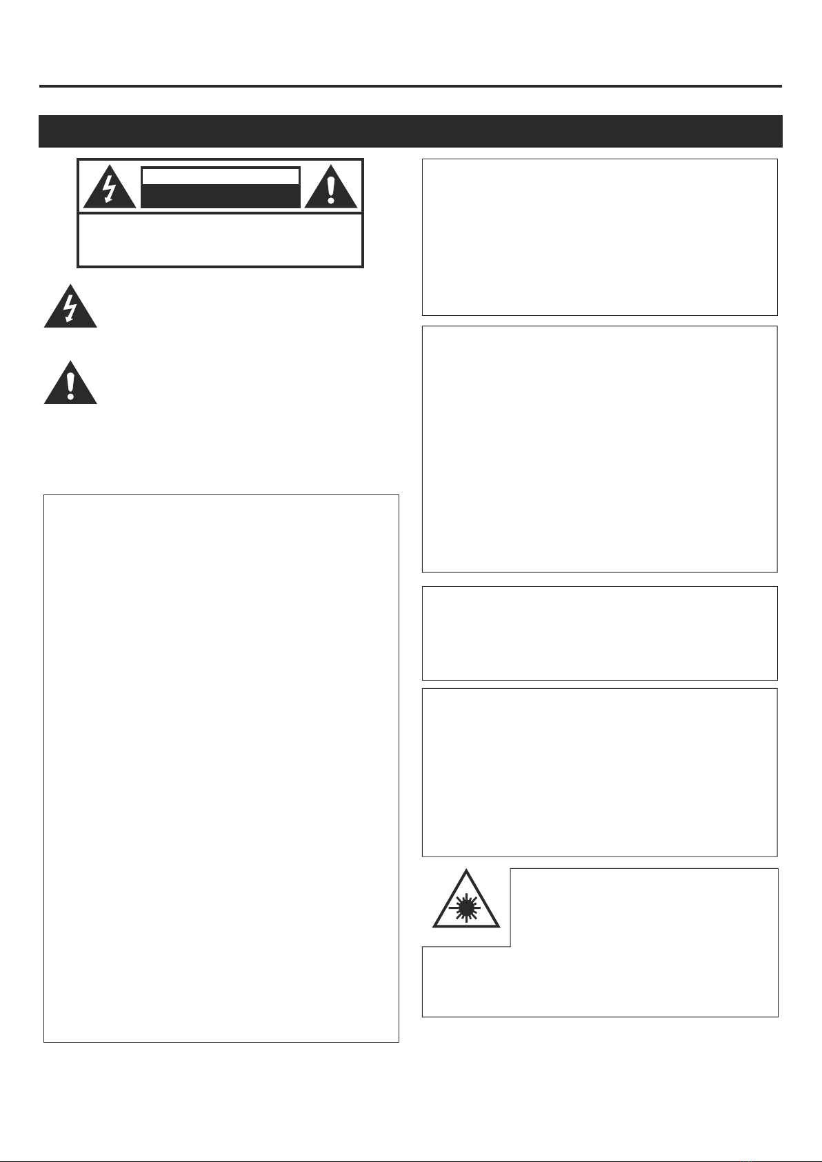
SAFETY I N STRUCTIONS
Before using the unit, b e s ure t o r ead all operating instructions carefully . P lease note t hat
these are general precautions and may not pertain to your unit.

22.
Unplug this product from the wall outlet and refer
servicing to qualified service personnel under the
following conditions:
A.When the power supply cord or plug is damaged.
B.If liquid has been spilled, or objects have fallen into
the product.
C.If the product has been exposed to rain or water.
D.If the product does not operate normally by following
the operating instructions. Adjust only those controls
that are covered by the operating instructions as an
improper adjustment of other controls may result in
damage and will often require extensive work by a
qualified technician to restore the product to its normal
operation.
E.If the product has been dropped or damaged in any
way.
F.When the product exhibits a distinct change in
performance-this indicates a need for service.
Damage Requiring Service 23.
Do not attempt to service it yourse lf as operating
instructions, do not attempt to service it yourself as
opening or removing covers may expose you to
dangerous voltage or other hazards. Refer all servicing
to qualified service personal.
Servicing
Note to CATV system installer
This reminder is provided to call the CATV system installers attention to Article 820-40
of the NEC that provides guidelines for proper grounding and, inparticular, specifies
that the cable ground shall be connected to the grounding system of the building, as
close to the point of cable entry as practical.
5

6
Thank you for purchasing products from American Audio Lab!
Contact us:
Interested in becoming a retailer or distributor of American Audio Lab
products ? Contact our sales department at 1-626-5828098.
For general information about American Audio Lab products, contact
us at 1-626-5828099.
For Technical Assistance, contact us at 1-626-5828099.
Monday to Friday, 8:30 am to 5:30 pm PST.

Mute
Slow
USB
Video
SD
N P/Audio L R/
OSD
Repeat
A B-
Return
ClearProgram
AngleSearch
PBC Subtitle
Title Setup
Menu Zoom
Enter
Step
Vocal
Cancel
Vol+
Vol-
#
DVD
Menu
Enter
iPod
Control
Eject
1
3
4
7
8
11
14
17
19
21
23
25
27
28
31
32
35
37
2
5
6
9
10
12
13
15
16
18
20
22
24
26
29
30
33
34
36
38
7
CONTROLS & F UNCTIONS
Remote Control Functions
1. Mute
2. Eject
3. USB (DVD/USB mode)
4. DVD (DVD/USB mode)
5. SD (DVD/USB mode)
6. Slow play
7. NTSC/PAL selector
8. Video
9. Audio
10. L/R selector
11. Numeric key pad
12. OSD (on screen display)
13. A-B (section repeat)
14. Program
15. Return
16. Clear
17. Search
18. Angle
19. PBC (playback control)
20. Subtitle
21. Title
22. Setup
23. Directional selector
24. Enter (confirm)
25. Menu
26. Zoom
27. Pause
28. Play
29. Stop
30. Step
31. Fast forward
32. Fast backward
33. Previous
34. Next
35. Vocal cancel
36. iPod control
37. Key control
38.
(Track、Time、Disc Time)
Volume

DVD
VCD
Mp3 PBC D
1 42 3 5 6 7 8 9
8
Front Panel Functions
LED Display Window
2.Eject button
10.L/R button
11.Numeric keys 0-9
27/28.Play/Pause button
29.Stop button
33.Previous button
34.Next button
35.Vocal cancel
37.Key changer
43.LED display window
44.MIC 1/2 volume
45.Echo button
46.Master volume
39.Karaoke on / off
40.Microphone jacks
41.Traydoor
42.SD Card reader
1.Disc t ype
2.In PLAY status
3.PBC on
4.In Pause status
5.Playback
6.Tray information
7.Time information
8.Dolby on
9.In Repeat status
Put i n Take off
Push
American Audio Lab Audio System
DMOS AMP
DIRECT SEARCH SYSTEM
MIC 1 VOL MIC 2 VOL ECHO
SD Cared reader
GO-210 TUTTI
MASTER VOL
KARAOKE
ON/OFF
L
R
#
VOCAL
CANCEL
234678
590
1
3735
103327/28
34292
41
40 43
11
46454442
39
MIC 1
MIC 2

Rear Panel Functions
9
47.Mic Tre
48.Mic Bas
49.Music Volume
50.Music Tre
51.Music Bas
52.BBE sound
53.Input select
54.Composite video output jack
55.Y.Pb.Pr.Video output jacks
56.USB jack
57.VGA output jack
58.S-video output jack
59.Coaxial output jack
60.Optical output jack
61.Aux input / output jacks
62.Video input jack
63.Audio return R/L jacks
64.Audio effect in / out jacks
65.Headphone
66.Mic/Line in (Bal)
67.DC 12V in
68.Power cord connection
69.Power on/off
70.R/L AUX speaker connector
America n Audio L ab Audi o System
MODEL NO:G O-210 TUTTI
INPUT:AC110V,60Hz
POW ER CONSUMPTION:200W MAX
P.M.P.O:2×200W / 4 ohms
RATE D IMPEDANCE: 4 ohms
FRE QUENC Y RESPONSE:45Hz~20kHz
SENSITIVITY: 87±2dB
RISK OF EL EC TRIC SHOCK
DO N OT O PEN
WARNING
AUDIO OUT PUT
SPEAKER IMPEDANCE: 4~16 ohms
MAX POWER:2×200W Left
Rig ht
70 6869 67
47 48 49 50 51 52
54 55
56 57
58
59 60
61
62
63
64
65
66
MIC TRE MIC BAS
MUSIC V OL UME
MUSIC TRE MUSIC BAS BBE SOUND INPUT SELECT
DVD
AUX
iPod
VIDEO Pr
Pb
Y
S-Video
COAX
OPTI
VIDEO OUTPUTD-OU T VGA OU T
USB
R
L
R
L
OUTIN
HEADPHONE
AC INPOWER
ON OFF
XLR-1
3
2
1
+
-
3
2
1
+
-
GROUND GROUND
XLR-2
AU DIO: EFFE CT
MIC/LINE IN(BAL)
IN OUT
R
L
VIDEO IN
AUX:AUDIO/VIDEO
MUSIC CONTROLMIC CONTROL
DC 12V IN
53

Power Cord Connection
There are two ways for the power which are AC110V / 60Hz and DC 12V.
1.Connect the power cable to the rear panel first.
2.Connect the power plug to the outlet (or accumulator).
3.Regular 12V auto battery could be applied for power source connected with DC 12V IN.
NOTE: Please check whether the voltage of your local power lines match this machine voltage range
(AC 110V or DC 12V) before getting connected.
WARNING: Please be sure that the power button is positioned at OFF after use.
Please unplug the power cord if nonuse for a long time.
AC/DC can not be used simultaneously.
10
AC110V
60Hz 2
1
Battery
DC 12V
OR
2
Connection
Microphone Connection
There a re two microphone jacks in the front panel of the machine.Plug the microphone cable into jacks.
1
GO-210 TUTTI
DC 12V IN
Put in Take off
Push
American Audio Lab Audio System
DMOS AMP
DIRECT SEARCH SYSTEM
MIC 1 VOL MIC 2 VOL ECHO
SD Cared reader
GO-210 TUTTI
MASTER VOL
KARAOKE
ON/OFF
L
R
#
VOCAL
CANCEL
234678
590
1
MIC 1
MIC 2

MUSIC VOLUME
MUSIC CONTROL
MIC CONTROL
OUTIN
AUDIO:EFFECT
AUX:AUDIO/VIDEO
TO TV S-VIDEO I N
GO-210 TUTTI
MUSIC VOLUME
MUSIC CONTROL
MIC CONTROL
OUTIN
AUDIO:EFFECT
AUX:AUDIO/VIDEO
Apply V ideo Cord ( the one with y ellow head) to connect V IDEO OUT jack o n G O-210 TUTTI with VIDEO IN
jack on TV.
Apply Audio Cord (white and red head) to connect AUX OUT jacks (L,R) on GO-210 TUTTI with AUDIO IN
jack on TV.
NOTE:This is only applied to a standard TV with AV function while playing disc.
11
Composite V ideo Output Connection
S-VIDEO C onnection
Apply S-VIDEO C ord t o c onnect S -VIDEO OUTPUT jack o n G O-210 TUTTI with S -VIDEO IN jack o n T V.
The TV should be set in S-VIDEO mode.Player setting is shown on PAGE 20.
TO-TV V IDEO I N
TO-TV A UDIO I N
GO-210 TUTTI

MUSIC VOLUME
MUSIC CONTROL
MIC CONTROL
OUTIN
AUDIO:EFFECT
AUX:AUDIO/VIDEO
MUSIC VOLUME
MUSIC CONTROL
MIC CONTROL
OUTIN
AUDIO:EFFECT
AUX:AUDIO/VIDEO
Y.Pb.Pr C onnection
Apply Y. Pb.Pr c ords to connect Y. Pb. Pr jacks on GO-210 TUTTI with Y. Pb. Pr IN jacks on the T V.
TV should be set in Y.Pb.Pr mode. For player setting, please see PAGE 20.
VGA Connection
Apply VGA cord to connect VGA jack on GO-210 TUTTI with TV/MONITOR.You will get a better picture from this
progressive scan function.Player setting is shown on PAGE 20.
GO-210 TUTTI
VIDEO
TO-PC VGA I N
TV /
MONITOR
12
TO-TV Y. Pb.Pr I N
GO-210 TUTTI

MUSIC VOLUME
MUSIC CONTROL
MIC CONTROL
OUTIN
AUDIO:EFFECT
AUX:AUDIO/VIDEO
MUSIC VOLUME
MUSIC CONTROL
MIC CONTROL
OUTIN
AUDIO:EFFECT
AUX:AUDIO/VIDEO
AUDIO CONNECTION
There a re 6 w ays t o c onnect t he GO-210 TUTTI with dif ferent machines.I n a ddition, GO-210 TUTTI is an all-in one
machine with amplifier and speaker.
Coaxial output
Optical output
Apply a C oaxial cord to connect t he digital amplifier/d ecoder with GO-210 TUTTI on COAXIAL jacks.
Apply an Optical c ord t o c onnect digital amplifier/d ecoder with GO-210 TUTTI on OPTICAL jacks.
13
5.1 c hannel digital amplifier
CENFL SL
FR SR SW
DVDCD
SW CEN SL SR FL FR
CD DVD
L
R
L
R
~100V-240V(50-60Hz)
COAXIAL OPTICAL
GO-210 TUTTI
5.1 c hannel digital amplifier
CENFL SL
FR SR SW
DVDCD
SW CEN SL SR FL FR
CD DVD
L
R
L
R
~100V-240V(50-60Hz)
COAXIAL OPTICAL
GO-210 TUTTI
Coax input
Optical input

MUSIC VOLUME
MUSIC CONTROL
MIC CONTROL
OUTIN
AUDIO:EFFECT
AUX:AUDIO/VIDEO
GO-210 TUTTI
AUX a udio input
GO-210 TUTTI could connect w ith e xternal audio source through AUX i nput jacks on the back p anel when the
Input Select below is switched to AUX status.
External audio source
( etc)MP3
14
MUSIC VOLUME
MUSIC CONTROL
MIC CONTROL
OUTIN
AUDIO:EFFECT
AUX:AUDIO/VIDEO
GO-210 TUTTI
Stereo HIFI amplifier
CENFL SL
FR SR SW
DVDCD
SW CEN S L SR FL FR
CD DVD
L
R
L
R
~100V-240V(50-60Hz)
COAXIAL OPTICAL
Apply Audio Cord( white and red head) to connect AUX O UT (L, R) jacks o n the back of GO-210 TUTTI with
D VD jacks on HiFi amplifier. Mixed music with vocal will be output when opened the micophone.
2 Channel Stereo output
Aux in
Aux out

MIC TRE MUSIC TRE MUSIC BAS BBE SOUND INPUT SELECT
VIDEO Pr
Pb
Y
S-Video
COAX
OPTI
VIDEO OUTPUTD-OUT VGA OUT
USB
R
L
R
L
HEADPHONE
AC INPOWER
ON OFF
XLR-1
3
2
1
+
-
3
2
1
+
-
GRO UND GR OUND
XLR-2
MIC/LINE IN(BAL)
IN OUT
R
L
VIDEO IN
GO-210 TUTTI
MUSIC CONTROLMIC CONTROL
OUTIN
AUDIO:EFFECT
AUX:AUDIO/VIDEO
MUSIC VOLUME
DVD
AUX
iPod
Canon input
15
Audio source
or
microphone
Apply Canon Cord to connect XLR-1/XLR-2 jacks on GO-210 TUTTI rear panel with external audio source
or microphone especially for long distance and better effect.
Canon Cord
DC 12V IN

Audio effect
16
GO-210 TUTTI could connect such as EQ、 TYPE jacks etc to the Audio Effect jacks according to their tastes.
MIC TRE MUSIC TRE MUSIC BAS BBE SOUND INPUT SELECT
VIDEO Pr
Pb
Y
S-Video
COAX
OPTI
VIDEO OUTPUTD-OUT VGA OUT
USB
R
L
R
L
HEADPHONE
AC INPOWER
ON OFF
XLR-1
3
2
1
+
-
3
2
1
+
-
GRO UND GROU ND
XLR-2
MIC/LINE IN(BAL)
IN OUT
R
L
VIDEO IN
GO-210 TUTTI
MUSIC CONTROLMIC CONTROL
OUTIN
AUDIO:EFFECT
AUX:AUDIO/VIDEO
MUSIC VOLUME
DVD
AUX
iPod
Effect
AUX INOUT
DC 12V IN

INTRODUCTION
Tray eject Reading disc
Your GO-210 TUTTI is a m ulti-format diisc p layer with a b uilt-in s tereo a mplifier and s peakers.
Simply connect your unit to a power source and you are ready to begin listening to CDs、MP3s
or singing karaoke. Connecting your GO-210 TUTTI to a television allows you to see the karaoke
lyrics and access menu options, or to watch a DVD movie.
1. Connect t he power cord on your an electrical outlet as previously described.GO-210 TUTTI to
2. Connect t he video output on your your television as previously described.GO-210 TUTTI to
3. Press t he POWER button o n t he .GO-210 TUTTI
4.Use numeric keypad to access directly tracks or chapters.
5. Adjust t he volume by the v olume c ontrol o n t he front of the GO-210 TUTTI or using
the V ol + a nd Vol– buttons(#39,pg.7) on your remote control.
17
Put in Take off
Push
American Audio Lab Audio System
DMOS AMP
DIRECT SEARCH SYSTEM
MIC 1 VOL MIC 2 VOL ECHO
SD Cared reader
GO-210 TUTTI
MASTER VOL
KARAOKE
ON/OFF
L
R
#
VOCAL
CANCEL
234678
590
1
MIC 1
MIC 2

MIC TRE MIC BAS
MUS IC VOLU ME
MUSIC TRE MUSIC BAS BBE SOUND INPUT SELECT
DVD
AUX
iPod
VIDEO Pr
Pb
Y
S-Video
COAX
OPTI
VIDEO OUTPUTD-OUT VGA O UT
USB
R
L
R
L
OU TIN
HEADPHONE
AC I NPO WE R
ON OFF
XLR-1
3
2
1
+
-
3
2
1
+
-
GROUND GROUND
XLR-2
AUDIO:EFFECT
MIC/LINE IN(BAL)
IN OUT
R
L
VIDEO IN
AUX:AUDIO/VIDEO
MUSIC CONTROLMIC CONTROL
Am erica n Aud io L ab Au dio Sys tem
MODEL NO:G O-210 TUTTI
INPUT:AC110V,60Hz
POWER CONSUMPTION:200W MAX
P.M.P.O:2×200W / 4 ohms
RAT ED IMPEDANCE: 4 ohms
FREQUENCY RESPONSE:45Hz~20kHz
SENSITIVITY: 87±2dB
RISK OF ELECTRIC SHOCK
DO NOT OP EN
WARNING
AUDIO OUT PU T
SPEAKER IMPEDANCE: 4~16 ohms
MAX POWER:2×200W Left
Ri ght
GO-210 TUTTI
USB POR T A ND OPERA TION
AUX S PEAKER CONNECTION
Right speaker Left s peaker
18
The U SB port on the back o f y our GO-210 TUTI provides the option to play files recorded on a U SB
flash drive in MP3,WMA,JPEG,AVI and VCD formats when the Input Select was set in DVD mode.
If no disc in the disc tray,the GO-210 TUTTI automatically loads data from the USB device.
If the player is playing a disc,press the STOP(#29,pg.7) to stop playing before connecting
a USB flash drive or hard drive.Once the USB flash drive or hard drive is connected,press the
DVD/USB button.The root directory of the connected USB device will display on the connected
television after a few seconds.Use the remote control's directional buttons(#23,pg.7) to select
the file you want to play.Press the ENTER(#24,pg.7) button to start playing from USB device.
GO-210 TUTTI provides you t he option to connect a p air of external speakers through the Auxiliary
speaker connectors(#70,pg.9) located on the back of the unit.
DC 12V IN
NOTE:
Video (MPEG 4,DIVX 5.0 UP) , Audio ( MP3 ) , Picture ( JPEG ).That is applied to both USB
disk and SD card.
The max size of hard drive can be up to 2G . And the format can be compatible with

INPUT SELECT MODES
DVD/USB/SD MODE
AUX MODE
With the player stopped, turn Input Select knob(#53,pg.9) to DVD on the back of the unit to enter this
mode.There will be audio avaible at the COAX、OPTI、and AUX OUT jacks. Video can also be
output at the S-Video、Video、Y.Pb.Pr and VGA OUT jacks. At this mode, audio and video
could be input through the DVD、USB or SD jack by pressing DVD ( #4,pg.7)、USB ( #3,pg.7) or
SD ( #5,pg.7) on the remote control.
NOTE:Please check the cord type and make sure for matching the jacks.
There are three modes to have to different audio/video source by the INPUT SELECT knob(#53,pg9).
iPod MODE
Press Aux b utton ( #5,pg.7) on the remote control or turn Input Select knob(#53,pg.9) to AUX on the back of
the unit to enter this mode.Audio can only be input and output through AUX IN and AUX OUT jacks. And video
could only be input and output by the VIDEO IN and VIDEO jacks when connected to such as portable DVD.
With the player stopped, turn Input Select knob (#53,pg.9) to iPod on the back of the unit to enter
this mode. Music with microphone will be avaible at the AUX OUT jacks at the back of the unit.
Besides, video can be output though the Video jack.
NOTE:Mixed music and microphone will be avaible at the AUX OUT jacks in any mode !
When the machine is playing under one mode, the other mode still working .
19

FUNCTIONS A ND OPERA TIONS
20
Press t o m ute t he audio.Press a gain to cancel.
Mute
1
Slow Play
5
The S low button( #6,pg.7) allows the user to slow the playback speed of DVDs and VCDs. While
playing a DVD,pressing this button to slow down the playback to ½ or normal speed in either
the forward or backward direction.When playing VCD discs the Slow button will slow the playback
to ½ or speed but only in the forward direction.Press the Slow button once for ½ speed and a
second time for speed. Pressing the Slow button again will result in normal play. When the
GO-210 TUTTI is playing in the slow mode,the audio output is disabled.
⅛
⅛
⅛
Video T ype Select
7
The N /P button( ) is used to switch between NTSC and PAL video format discs. #7,pg.7
5. Depress t h e Stop button( ). #29,pg.7
6. Depress t h e N/P button .
7. Within 2 s econds depress t he Enter b utton ( ). #24,pg.7
8. Repeat t h is process a s m any times a s n ecessary to get the v ideo type necessary for p roper
display on the a ttached video monitor.
This process a llows the u ser t o c hoose between MULTI, SYSTEM,NTSC and P AL. Settings f or
480P, 5 76P, a nd 720P( HDTV on ly) s hould be selected i n t he SETUP menu described later.
NOTE: O c casionally when adjusting the GO-210TUTTI’s s ettings, t he user may c reate ituation
where t he system needs to be reset t o factory defaults b ecause t he user may n o longer be able
to view system information on the video monitor. To reset all functions to the factory default:
1. Turn the power of f u sing the P ower button o n t he GO-210 TUTTI.
2. back on.Turn the power
3. Press t h e eject b utton o n t he GO-210 TUTTI.
4. Using t h e GO-210 TUTTI’s fr ont panel numeric keys,enter 2 22888
5. Press t h e Stop button
6. T using the Power button on the GO-210 TUTTI.urn the power off
7. .Turn the power back on
Video Output Select
8
Once your video monitor is connected t o t he GO-210TUTTI, select t he correct video for y our
displayas follows:
A.S-VIDEO: for S-VIDEO connection
B.Y.Pb.Pr: for Y.Pb.Pr connection
C.VGA: for VGA connection,can connect to a PC monitor
1.S-video will be avaible at any time.
2.Only one of the S-video,Y.Pb.Pr,VGA jacks can be output at one time according to the Video output
format in Setup
Table of contents