Meyer LD-3 User manual

OPERATING INSTRUCTIONS
LD-3 Air Attenuation Compensating Line Driver
Keep these important operating instructions.
Check www.meyersound.com for updates.

ii
DECLARATION OF CONFORMITY ACCORDING TO ISO/IEC GUIDE 22 AND EN 45014
Manufacturer's Name:
Meyer Sound Laboratories Inc.
Manufacturer's Address:
2832 San Pablo Avenue
Berkeley, CA 94702-2204, USA
declares that the products
Product Name: LD-3 Line Driver
Product Options: All
conforms to the following Product Specications
Safety: EN 60065:1998
EMC: EN55103-1: 1997 emmission1
EN55103-2: 1997 immunity2
This device complies with the requirements of the
Low Voltage Directive 73 / 23 / EEC and the
EMC Directive 89 / 336 / EEC.
This device also complies with EN 55103-1 & -2.
Operation is subject to the following two conditions:
(1) this device may not cause harmful interference, and
(2) this device must accept any interference received, including
interference that may cause undesired operation.
Supplementary Information
The product herewith complies with the requirements of the Low
Voltage Directive 73/23/EEC and the EMC Directive 89/336/EEC.
Ofce of Quality Manager
Berkeley, California USA
July 3, 2003
European Contact: Your local Meyer Sound dealer or Meyer Sound
Germany, GmbH. Carl Zeiss Strasse 13, 56751 Polch, Germany.
Telephone: 49.2654.9600.58 Fax: 49.2654.9600.59
Environmental specications for Meyer Sound Electronics products
Operating temperature 0°C to +45°C
Non-operating temperature -40°C to +75°C
Humidity to 95% at 35°C
Operating altitude to 4600 m (15,000ft)
Non-operating altitude to 6300 m (25,000ft)
Shock 30 g 11 msec half-sine on each of
6 sides
Vibration 10 Hz to 55 Hz (0.010 peak-to-peak
excursion)
© 2003 Meyer Sound. All rights reserved.
LD-3 Operating Instructions
The contents of this manual are furnished for informational purposes only, are subject to change without notice, and should not be construed as a
commitment by Meyer Sound Laboratories Inc. Meyer Sound assumes no responsibility or liability for any errors or inaccuracies that may appear
in this manual. Except as permitted by applicable copyright law, no part of this publication may be reproduced, stored in a retrieval system, or
transmitted, in any form or by any means, electronic, mechanical, recording or otherwise, without prior written permission from Meyer Sound.
Meyer Sound, Meyer Sound MAPP Online, SIM and QuickFly are registered trademarks of Meyer Sound Laboratories Inc. (Reg. U.S. Pat. & Tm.
Off.). All third-party trademarks mentioned herein are the property of their respective trademark holders.
Printed in the U.S.A.
Part Number: 05.118.040.01 B
European Office:
Meyer Sound Lab. GmbH
Carl Zeiss Strasse 13
56751 Polch, Germany
Made by Meyer Sound Laboratories
Berkeley, California USA

iii
SYMBOLS USED
These symbols indicate important safety or operating features in this booklet and on the chassis:
1. Read these instructions.
2. Keep these instructions.
3. Heed all warnings.
4. Follow all instructions.
5. Do not use this apparatus near water.
6. Clean only with dry cloth.
7. Do not block any ventilation openings. Install
in accordance with Meyer Sound's installation
instructions.
8. Do not install near any heat sources such as radiators,
heat registers, stoves, or other apparatus that produce
heat.
9. Do not defeat the safety purpose of the grounding-
type plug. A grounding-type plug has two blades and
a third grounding prong. The third prong is provided
for your safety. If the provided plug does not t into
your outlet, consult an electrician for replacement of
the obsolete outlet.
10. Protect the power cord from being walked on
or pinched particularly at plugs, convenience
receptacles, and the point where they exit from the
apparatus. The AC mains plug or appliance coupler
shall remain readily accessible for operation.
11. Only use attachments/accessories specied by Meyer
Sound.
12. Use only with the caster rails or rigging specied by
Meyer Sound, or sold with the apparatus. Handles are
for carrying only.
13. Unplug this apparatus during lightning storms or when
unused for long periods of time.
14. Refer all servicing to qualied service personnel.
Servicing is required when the apparatus has been
damaged in any way, such as the power-supply cord
or plug is damaged, liquid has been spilled or objects
have fallen into the apparatus, the apparatus has
been exposed to rain or moisture, does not operate
normally, or has been dropped.
!
Dangerous voltages: risk of
electric shock
Important operating
instructions
Frame or chassis Protective earth ground
Pour indiquer les risques
résultant de tensions
dangereuses
Pour indequer important
instructions
Masse, châssis Terre de protection
Zu die gefahren von
gefährliche spanning zeigen
Zu wichtige betriebs-
anweisung und unter-
haltsanweisung zeigen
Rahmen oder chassis Die schutzerde
Para indicar voltajes
peligrosos.
Instrucciones importantes
de funcionamiento y/o
manteniento
Armadura o chassis Tierra proteccionista
IMPORTANT SAFETY INSTRUCTIONS

iv

v
CONTENTS
INTRODUCTION 1
How to use this manual 1
Introducing The LD-3 Air Attenuation Compensating Line driver 1
CHAPTER 1: AC Power Requirements 3
CHAPTER 2: Audio and System Controls 5
Audio Input 5
Atmospheric Correction 5
Temperature 6
Altitude 6
Relative Humidity 6
Array Correction 6
Array Type 7
Array Size 7
The Enter Button 7
Master Input Channels A and B 8
Channels 1-3 (A and B) Outputs 8
Distance Control 9
Insert Switch 10
Insert Inputs 10
Send Outputs 10
Subs A and B 10
Insert Switch 11
Insert Inputs 11
CHAPTER 3: System Design, Integration, and Optimization 13
Example Design Congurations 13
Meyer Sound MAPP Online® 13
Loudspeaker/Subwoofer Integration 14
SIM® Measurement System 15
Source Independent Measurement Technique 15
Applications 15
Appendix A: Specications 17
Appendix B: Example Congurations 19
Appendix C: Signal Flow Diagram 22

vi

1
INTRODUCTION
HOW TO USE THIS MANUAL
As you read this manual, you’ll nd gures and diagrams
to help you understand and visualize what you’re reading.
You’ll also nd numerous icons that serve as cues to ag
important information or warn you against improper or
potentially harmful activities. These icons include:
A NOTE identies an important or useful
piece of information relating to the topic
under discussion.
A TIP offers a helpful tip relevant to the topic
at hand.
!
A CAUTION gives notice that an action can
have serious consequences and could cause
harm to equipment or personnel, delays, or other
problems.
INTRODUCING THE LD-3 AIR ATTENUATION
COMPENSATING LINE DRIVER
Once a challenge to line array system design, environmental
conditions are just another part of the mix with the eight-
channel LD-3 (Figure i.1), a powerful tool from Meyer Sound
for optimizing large-scale sound reinforcement systems by
correcting frequency response for the attenuation of sound
in air.
Figure i.1. LD-3 line driver, front and rear panels
Feed the day’s weather report into the LD-3 through its
Atmospheric Correction and Relative Humidity knobs,
dial-in the type of loudspeakers and distance of the throw
for each section of the array, and the LD-3 goes to work.
A RISC microcontroller retrieves response correction
coefcients and corrects the output to compensate for the
air absorption for those weather conditions.
By utilizing multiple-variable atmospheric loss equations
and pre-calculated Meyer Sound MAPP Online® (for more
information, see Chapter 3) stored values, the LD-3 delivers
results quickly and efciently. Its high-quality, digitally-
controlled analog lters provide the best of both worlds:
the low latency and wide dynamic range of analog and
the nimble, precise, repeatable results of digital. The LD-3
corrects frequency response up to 16 kHz at a resolution
down to 1 dB.
Figures i.2, i.3, and i.4 are example frequency attenuation
curves for three different temperatures with a xed distance
of 100 meters, at seven values for relative humidity.
Depending on the atmospheric conditions and the distance
the array is throwing, the number of possible correction
combinations is staggering – and achievable with the LD-3.
Figure i.2. Air absorption for 10 degrees C at 100 meters
Figure i.3. Air absorption for 20 degrees C at 100 meters
INTRODUCTION

2
INTRODUCTION
Figure i.4. Air absorption for 30 degrees C at 100 meters
In addition to weather correction, the LD-3’s unique ability
to compensate for low to mid-low frequency build-up allows
the user to ne-tune each channel driving an M Series array.
Set the type of loudspeaker being used and the number of
cabinets in the array, and the LD-3’s stored presets do the
rest.
Figure i.5 is an example of a correction made to a MILO
array with eight loudspeakers. By applying this correction
the result is an incredibly at system response across a
wide range of frequencies.
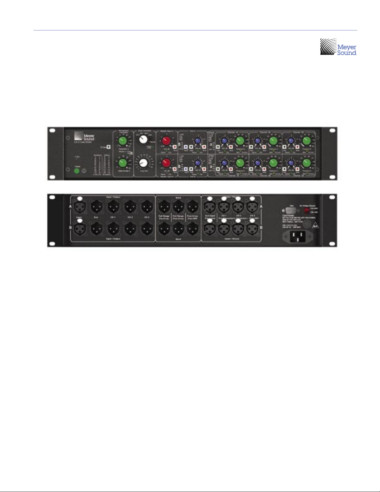
Each of the LD-3’s two master channels consists of a
Master Input section, a dedicated subwoofer output,
and three outputs to required control. Three Sends and
four Insert/Returns provide the control to route the signal
and incorporate additional signal processing, such as
parametric equalization.
The Master Input section provides individual channel Gain
adjustment from –12 to +6 dB, an illuminated Mute switch,
Signal/Clip indicator, and a switchable High-Pass Filter
(0, 80, or 160 Hz) for boundary correction or optimizing
crossover to subwoofers. Master environmental controls
include Temperature (0° to 45° C), Altitude (switchable in
three ranges: 0-800, 800-2200, and 2200+ m) and Relative
Humidity (10 to 100%).
Individual outputs provide Gain trim from –6 to +6 dB,
Signal/Clip indicator, an illuminated Mute switch, illuminated
Send/Return Insert switches, and Distance controls to
dene the throw from each sound system branch to its
audience coverage area up to 150 meters (492 feet).
The LD-3’s dedicated subwoofer control sections feature
Polarity switches, Gain trim from –6 to +6 dB, mute, Signal/
Clip/Mute indicator, and Send/Return Insert switches.
In addition, a high-quality Low-Pass Filter is supplied,
switchable to 0, 55, or 80 Hz.
NOTE: While each of the LD-3’s output fully
independent channels can be used to divide
a main system into subsystems, they can also be
used to control downll, front ll, and delay systems,
allowing independent signal levels.
In addition to its sophisticated environmental and array
control functions, the LD-3 can integrate different types of
Meyer Sound self-powered loudspeakers into a cohesive
system, while maintaining signal integrity for long cable
paths.
The LD-3 occupies two standard 19-inch relay rack spaces.
Flash memory for future expansion is built in, and all input
and outputs are electronically balanced and utilize XLR
(A-3) type connectors. The AC inlet is an IEC standard male
connector, protected with
a 250 mA 250 V fuse, and
switchable in the ranges of
105-125 and 210-250 VAC.
Information and specications
are applicable as of the date
of this printing. Updates and
supplementary information
are posted on the Meyer
Sound web site at:
www.meyersound.com
You may contact Meyer
Sound Technical Support at:
Tel: +1 510 486.1166
Fax: +1 510 486.8356
Email: techsupport@
meyersound.com
Figure i.5. Correction needed shown with eight MILO loudspeakers at 35 meters

3
CHAPTER 1
The LD-3 uses an international standard IEC 320 mains
AC inlet. This convenient rear panel receptacle accepts
many power cord types for mains outlets used throughout
the world. The LD-3 must have the correct power cord for
the AC power in the area in which it will be used.
The LD-3 operates in two AC voltage ranges: 105 – 125 V
and 210 – 250 V, at 50 or 60 Hz (Figure 1.1). The voltage
select switch on the rear panel must be set to the proper
voltage before applying AC power. Connecting the LD-3
to a 225 V AC source with the voltage select switch in the
105 – 125 V position could blow the fuse.
Figure 1.1. Voltage switch and power inlet locations on the LD-3
!
CAUTION: Always unplug the power cord
before changing the voltage select switch.
When the LD-3 is powering on, it takes about two seconds
to read stored atmospheric and array correction values,
and illuminated Enter button (covered in Chapter 3, “Audio
and System Controls”) changes from red to green.
Audio outputs are muted internally during normal power
on and off, and in case of sudden loss of AC power or
unstable line voltage. This precaution prevents noise
transmission — and possible damage — to interconnected
devices.
!
CAUTION: Don’t use a ground-lifting
adapter or cut the AC ground pin. To avoid
electrical shock and damage to the unit, use
the power cord specied by Meyer Sound or an
equivalent that satises the requirements of the
local safety testing agency.
!
CAUTION: Do not operate the unit if the
power cables are frayed or broken.
Always disconnect the power cord before changing the
fuse. To replace the fuse, insert a at-blade screwdriver in
the fuse cap and gently turn counterclockwise; the fuse
springs from its socket. Replace only with a 5 x 20 mm,
T 250 mA, 250 V, time-lag fuse that conforms to identical
safety agency standards. If the fuse blows again, contact
Meyer Sound for repair information.
CHAPTER 1: AC POWER REQUIREMENTS
Voltage Select
Switch
IEC 320 Male
Power Outlet

4
CHAPTER 1

5
CHAPTER 2
Much more than a system integration tool, the LD-3 line
driver uses its sophisticated circuitry to bring consistent
and predictable results to any M Series line or curvilinear
array design. This chapter will help you understand
and harness the power of the LD-3's audio and system
controls.
AUDIO INPUT
The LD-3 presents a 10 kOhm balanced input impedance
to a three-pin XLR connector wired with the following
convention:
Pin 1 — Connected to Earth (AC) ground and chassis
through ESD (Electrostatic Discharge) absorption
and EMI/RFI (Electromagnetic/Radio Frequency
Interference) lters
Pin 2 — Signal (+)
Pin 3 — Signal (-)
Case — Earth (AC) ground and chassis
The LD-3 is balanced in and out, and consequently does
not change the polarity unless the “Sub Polarity” switch is
engaged on the Sub output section. Pins 2 and 3 carry the
input as a differential signal. Use standard audio cables
with XLR connectors for balanced signal sources.
The audio input signal should always be applied between
pins 2 and 3.
NOTE: All inputs employ ESD absorbers
and RF lters.
Pin 1 is connected to the unit's chassis and acts as a
safety and current bleed to earth for the ESD and EMI/RFI
interference coupled onto the shield of the input cable. Pin
1 is only for bleeding noise to ground, and connecting an
audio signal between pins 1 and 2, or pins 1 and 3, results
in a noisy audio signal. Most modern balanced audio
sources (electronically balanced or transformer output)
conform to the wiring convention described above and
interface correctly with the LD-3.
ATMOSPHERIC CORRECTION
The LD-3’s Atmospheric Correction section (Figure
2.1) uses special atmospheric loss equations and pre-
calculated Meyer Sound MAPP Online® stored values
from a 2 MB lookup table to correct for key environmental
conditions.
Figure 2.1. The Atmospheric Control section is at the heart of the
LD-3.
Controls are included for:
Temperature
Altitude (atmospheric pressure)
Relative humidity
Distance
NOTE: The Distance controls – featuring
large green knobs to match the color of the
green temperature and relative humidity knobs
– are located in sections for individual Channels 1-
3 (A and B) outputs, discussed later in this chapter.
NOTE: Atmospheric correction may be
disabled per channel on each of the three A
and B Output Channels by setting the distance to
zero.
Settings are read with 8-bit resolution and a range of
coefcient indices are fed to the output channels. The
result is corrected frequency response for the attenuation
of sound in air up to 16 kHz, with a resolution of
approximately 1 dB.
CHAPTER 2: AUDIO AND SYSTEM CONTROLS

6
CHAPTER 2
7
CHAPTER 2
Temperature
The green Temperature control allows you to set
temperature in 1° increments from 0° to 45° C. A
convenient Fahrenheit (F) to Celsius (c) conversion table is
located to the bottom left of the Atmospheric Correction
section (Figure 2.2).
Figure 2.2. The LD-3 includes a temperature conversion reference
table stenciled on its front panel.
Setting temperature is the rst step in the atmospheric
correction chain; the LD-3 takes the temperature setting
and uses it with the other environmental coefcients to nd
the correction needed across the LD-3’s frequency range.
Altitude
The altitude switch supports three ranges:
0 to 800 m (0 to 2,624 ft) above sea level
800 to 2200 m (2,624 to 7,217 ft) above sea level
2200+ m (7,217 ft) above sea level
Setting the altitude noties the LD-3 of the atmospheric
pressure; this setting corresponds to an index into a
function which has been pre-solved; the LD-3 then
changes how much output correction is needed due to
different atmospheric pressure levels.
Relative Humidity
The green Relative Humidity control allows the user to
dial-in relative humidity from 10 to 100% in increments
from 1 to 5% (the incremental range increases as humidity
increases).
The effect of humidity on the attenuation of sound
is perhaps the most critical aspect of the LD-3’s
environmental functionality, and is a fascinatingly complex
topic all to itself (and well beyond the scope of this
guide). Although it’s generally true that the LD-3 will boost
frequencies (particularly high frequencies) at an increasing
rate as temperature and altitude go up, the effects of
humidity are more complex, with few observable ranges
that show a consistent, incremental increase.
For instance, at 16 kHz and temperatures above 25° C,
a critical range is roughly 10-30% humidity. As shown in
Figure 2.3, the higher the humidity in this range, the less
air attenuation at that frequency – drier air needs less
boost (not a completely intuitive notion in any case).
However, at other humidities (not to mention other
temperatures, altitudes and distances) outside of this
example range, the rate and pattern of attenuation
behaves in other, less intuitive ways.
Because the LD-3’s atmospheric
control functions are logarithmic
rather than exponential (unlike
simple lters, for example), they
will not always behave in ways
you expect “normal” circuitry to
behave. For instance, turning
the Relative Humidity knob to
right doesn’t mean that the LD-
3 is necessarily adding more
correction (it could be adding
less).
ARRAY CORRECTION
The LD-3’s unique ability to
correct the overall frequency
response of the line or curvilinear
array itself enables you to further
ne-tune your system design to
correct natural array behavoir,
such as low frequency build-up.
Figure 2.3. Air Absorption per meter at 16 kHz

6
CHAPTER 2
7
CHAPTER 2
The Array Correction section (Figure 2.4), lets you set the
type of M Series loudspeaker using the Array Type selector
switch and the number of cabinets in the array with the
Array Size control.
Figure 2.4. The LD-3’s Array Correction section
Array Type
The gray Array Type selector (the top knob in the Array
Correction section) is a switch that controls the assignment
of the LD-3’s Array Correction function to any of the
following M Series loudspeakers:
M1D ultra-compact curvilinear array loudspeaker
M2D compact curvilinear array loudspeaker
MILO high-power curvilinear array loudspeaker
M3D line array loudspeaker
The Remote setting of the Array Type selector (bottom right
side) is for establishing a data link with MAPP Online and
downloading a pre-calculated array correction into the
LD-3.
TIP: Setting the selector to Remote disables
the Array Size selector (covered in the next
section).
After loading data via the LD-3’s serial Data Port, the
Program Loaded LED light, located just below the Remote
setting, illuminates.
!
CAUTION: An unlabeled notch – reserved
for future use – exists between the M3D and
Remote settings on the Array Type selector. Setting
the selector to this notch disables Array Correction
functionality.
NOTE: The rmware and ROM (Read Only
Memory) which support the LD-3’s array
correction functions are upgradeable in the eld.
Contact Meyer Sound or visit the Meyer Sound Web
site at www.meyersound.com for more information
on when this feature and upgrades will be available.
Array Size
You can set the number of cabinets in your array – up to
24 loudspeakers per channel – using the gray Array Size
control. For example, if you have two MILO arrays (typically
a left and right array) of 12 cabinets each, you would set the
Array Size selector to 12.
NOTE: Setting the Array Size selector to 1
disables Array Correction functionality.
Array correction is also applied to the Sub outputs, and,
when active, attenuates the Sub outputs. The Sub section’s
Gain trim, from –6 to +6 dB, should be used if additional
Gain on the Sub outputs is needed.
THE ENTER BUTTON
When the controls in the Atmospheric and Array Correction
sections are adjusted, press the illuminated Enter button
(Figure 2.5) to enable the changes.
Figure 2.5. The Enter button
Use the Enter button each time a change is made for the
following LD-3 functions:
Temperature
Altitude
Relative humidity
Distance (in any channel)
Array Type
Array Size
The Enter button changes from green to red once a change
is made on any of the above controls, indicating that it
needs to be pressed to update your changes; when the
Enter button is pressed, the LD-3 registers the change(s)
and the Enter button changes back to green.

8
CHAPTER 2
9
CHAPTER 2
For example, if the Temperature is set to 25° and the
Relative Humidity to 40%, press Enter, then change the
Temperature to 30°; press Enter again for the LD-3 to
register the new temperature.
MASTER INPUT CHANNELS A AND B
Master input channels A and B (Figure 2.6) are equipped to
control a full-range main system.
Front Panel Rear Panel
Figure 2.6. Master input channels A and B
Each Master Input channel has an illuminated mute switch,
signal/clip LED indicator, a switchable high pass lter, and
gain. For each channel, the controls perform these functions:
The gain control sets the overall level from –12 to +6 dB.
The illuminated Mute switch mutes all channel outputs,
which ash red when muted.
NOTE: When muting a master channel, you
are effectively muting the individual output
circuits located for each sub-channel. Hence each
output channel Mute switch will ash red, but its
Signal/Clip LED will still be active.
The bi-colored Signal/Clip LED indicates input signal
presence and level with a variable intensity green color,
and clipping with ashing red.
The High Pass Filter switch lters the input signal at
0, 80, or 160 Hz for boundary correction or optimizing
crossover to subwoofers. The lter affects Channels 1-3
for each Master Input channel A and B.
NOTE: The High-Pass Filter set to 160 is
identical to setting the “Lo-cut” lter on the
LD-1A and LD-2 line drivers; it is a 2nd Order (12 dB/
octave) at 162 Hz with a Q of 1.82. The 80 Hz lter is
an elliptical lter with fast initial attenuation – without
the phase shift associated with lters of higher order.
These lters are used to optimize integration with
subwoofers; in several cases they can augment an array’s
headroom by ltering low frequencies out.
NOTE: When driving loudspeakers with high-
pass lters and/or subwoofers with low-pass
lters engaged, phase shift caused by the lters in
the region where frequencies overlap may require
that you change subwoofer polarity — even if they
are co-planar or near each other.
CHANNELS 1-3 (A AND B) OUTPUTS
Six individual output channels – three for each Master Input
channel –provide Gain trim, illuminated Mute switches,
Signal/Clip indicators, and Insert switches (Figure 2.7). In
addition, individual distance controls dene the throw from
each sound system branch to its audience coverage area
up to 150 meters.
Front Panel
Rear Panel
Figure 2.7. The LD-3’s output channel section
For each channel, the controls perform these functions:
The Gain control sets the output level from –6 to +6 dB.
The illuminated Mute switch mutes the channel, ashing
red when muted.
The bi-colored Signal/Clip LED indicates signal
presence and level with a variable intensity green color,
and clipping with ashing red.

8
CHAPTER 2
9
CHAPTER 2
NOTE: Although the LD-3 offers a large gain
range (-6 to +6 dB) for each output, gain
tapering is not recommended for arrays. Adjusting
zones with an overall amplitude control for each
zone results in the following:
1. Directionality decreases.
2. Low-frequency headroom decreases.
3. The length of the line or curvilinear array
column is effectively shortened.
Distance Control
The green Distance control allows you dial-in the throw from
the array on each output channel, from 0 to 150 meters.
NOTE: Setting distance to 0 meters bypasses
the atmospheric correction functions.
A convenient feet (ft) to meters (m) conversion table is
located to the bottom left of the Atmospheric Correction
section (Figure 2.8).
Figure 2.8. The LD-3 includes an easy distance conversion reference
table stenciled on its front panel.
Setting the Distance enables the LD-3 to adjust the
correction curve according to the throw of the loudspeakers
on each channel. This setting corresponds to coefcients
(in increments from 2 to 10, increasing as distance
increases) which provide just the right amount and shape
of correction as a function of the other atmospheric
variables (Temperature, Altitude, and Relative Humidity). As
suggested by Figure 2.9, there are a multitude of correction
scenarios for even a handful of distances.
NOTE: After dialing in a new distance for any
channel, press the Enter button.
Figure 2.9. Sample atmospheric correction curves for the attenuation of sound in air at 10, 20, 40 and 80 meters.

10
CHAPTER 2
11
CHAPTER 2
Once the correction changes are enabled, press the Enter
button and the LD-3 changes how much correction is
needed due to the throw of your M Series line or curvilinear
array on the channel.
Insert Switch
Each output channel utilizes an Insert switch which allows
you to add outboard signal processing such as parametric
equalization. Figure 2.10 shows the Insert/Return Inputs, as
well as the auxiliary output section (Sends), with a Meyer
Sound CP-10 complementary phase parametric equalizer.
Figure 2.10. The LD-3’s back panel showing Sends and Returns for
1-3, A & B; a CP-10 can be added to the signal processing chain
!
CAUTION: The LD-3’s insert inputs are not
normalized; if the Insert switch is depressed
with nothing connected, the channel will be
effectively muted.
Insert Inputs
The Insert/Returns — one for each Channel 1-3 (A and B
— inputs are not affected by the setting of the High-Pass
Filter (pre-HPF) but are affected by the settings of the
Atmospheric Correction (post-atmospheric correction).
Send Outputs
The LD-3 features three Sends that are straightforward
and are derived from three different places before the
atmospheric correction (pre-atmospheric) in the signal path:
Full Range Pre-Array –The output signal is sent to your
outboard equipment without any array correction and
no ltering.
Full Range Post-Array – The output signal is sent to
your outboard equipment with full array correction and
no ltering.
Post-Array Post-HPF – The output signal is sent to
your outboard equipment with full array correction with
the high pass lter for the master channel (A or B) on.
SUBS A AND B
Two subwoofer control sections (Figure 2.11) feature
Polarity switches, Gain trim, illuminated Mute switches,
Signal/Clip indicators, and Insert switches to accommodate
outboard signal processing such as parametric equalization
and/or delay.
Front Panel Rear Panel
Figure 2.11. The LD-3’s sub section
For each of the two Sub channels, these controls perform
the following functions:
The Gain control sets the output level from –6 to +6 dB.
The illuminated Mute switch mutes the channel, ashing
red when muted.
The bi-colored Signal/Clip LED indicates signal
presence and level with a variable intensity green color,
and clipping with ashing red.
The blue illuminated Polarity switch allows you to
change polarity where as needed, according to the
subwoofer you’re using and its interaction with the
primary line or curvilinear array(s) in your design.
The Low Pass Filter switch employs a smooth, high-
quality elliptical lter at 55 or 80 Hz; the lter can be
disabled by ipping the switch to “Off.”

10
CHAPTER 2
11
CHAPTER 2
Insert Switch
Each Sub channel utilizes an Insert switch (Figure 2.12)
which, when engaged, is useful for driving a sub with a
different send or output from a console, or other outboard
equipment, if desired.
Figure 2.12. The LD-3’s Sub inserts
!
CAUTION: The Sub section’s Insert inputs
are not normalized; if the Insert switch is
depressed with nothing connected, the channel will
be effectively muted.
Insert Inputs
The Insert/Returns are not affected by the array correction,
but are affected by the Low-Pass Filter. The Sub section’s
inserts have a summing stage. If not engaged, the LD-3 will
sum the signal from the main input with the signal from the
Insert input. This can be useful for making a mono sum left
and right channels to drive the subs mono from the main
inputs.

12
CHAPTER 2

13
CHAPTER 3
The LD-3 opens up a number of design and integration
scenarios. Its versatility, in conjunction with different M
Series loudspeakers and/or subwoofers, gives you the
freedom to not only plan for the atmospheric conditions
and optimized the array, but to hone the design through
quantitative Meyer Sound tools and software. This chapter
will take you through some example congurations and
introduce you to some real-world options for achieving your
design quickly and efciently.
EXAMPLE DESIGN CONFIGURATIONS
The multiple input, output, insert/returns, and sends on the
LD-3 makes the unit very versatile; it can accommodate
a number of congurations to satisfy a wide number
of applications. See Appendix B for three example
congurations that demonstrate the exibility and utility of
the LD-3.
MEYER SOUND MAPP ONLINE
To quantitatively plan your system design, Meyer Sound
provides MAPP Online (Figure 3.1), a powerful, cross-
platform, Java-based application for accurately predicting
the coverage pattern, frequency response, impulse
response, and maximum SPL output of single or arrayed
Meyer Sound loudspeakers.
Figure 3.1. MAPP Online is an intuitive, powerful system design tool.
Residing on your computer, MAPP Online facilitates
conguring arrays of a wide variety of Meyer Sound
products and, optionally, denes the environment in which
they will operate, including air temperature, pressure, and
humidity, as well as the location and composition of walls.
You can nd MAPP Online at:
www.meyersound.com/products/software/mapponline
NOTE: In order to use MAPP Online, you
will need to register by clicking “Apply for
MAPP Online” on the Web page listed above. After
registration and upon approval, an e-mail will be
sent to you with a username and password along
with the address for the Web page where you can
download MAPP Online. Online instructions will
guide you through the download and setup process.
As its name indicates, MAPP Online is an online application:
when a prediction is requested, data is sent over the
Internet to a high-powered server at Meyer Sound that
runs a sophisticated acoustical prediction algorithm using
high-resolution, complex (magnitude and phase) polar data.
Predicted responses are returned over the Internet and
displayed on your computer in color.
With MAPP Online, you can:
Plan an entire portable or xed loudspeaker system and
determine delay settings for ll loudspeakers.
Clearly see interactions among loudspeakers and
minimize destructive interference.
Place microphones anywhere in the sound eld and
predict the frequency response, impulse response, and
sound pressure level at the microphone position using
MAPP Online’s Virtual SIM feature.
Rene your system design to provide the best coverage
of the intended audience area.
Use a virtual VX-1 program equalizer to predetermine
the correct control settings for best system response.
Gain valuable load information about the array to
determine rigging capacities.
MAPP Online enables you to come to an installation
prepared with a wealth of information that ensures the
system will satisfy your requirements “out of the box”
– including basic system delay and equalization settings. Its
accurate, high-resolution predictions eliminate unexpected
onsite adjustments and coverage problems. With MAPP
Online, every sound system installation has a maximum
chance of success.
MAPP Online is compatible with Windows, Linux, Unix,
and Apple Macintosh computers running Mac OS X version
10.1.2 or higher. The MAPP Online Web page above lists
additional system requirements and recommendations.
CHAPTER 3: SYSTEM DESIGN, INTEGRATION, AND OPTIMIZATION

14
CHAPTER 3
15
CHAPTER 3
LOUDSPEAKER/SUBWOOFER INTEGRATION
Using the LD-3’s lters helps to easily integrate and
optimize your M Series arrays with subwoofers. High-pass
lters augment array headroom by removing frequencies
near the low end of the loudspeaker's operating range,
while low-pass lters can remove unwanted mid-low
frequencies reproduced by the subwoofers.
NOTE: Full-range signals may be applied to
Meyer Sound’s self-powered loudspeakers
and subwoofers because they have built-in active
crossovers. However, the use of external lters – like
the ones in the LD-3 – is optional, and should be
used very carefully to avoid phase shifts that can
cause cancellations or dips in the response.
The use of these lters reduces areas of overlap and
minimizes the interaction and possible cancellations
between subsystems, usually resulting in highly desirable
behavior, such as very at frequency response. As shown
in Tables 3.1 through 3.8, some of the loudspeaker and
subwoofer combinations you can implement using the
LD-3’s ltering capabilities can go a long way toward ne-
tuning your system.
All data in Tables 3.1 through 3.8 are based on designs
in a close-proximity, coplanar orientation, at a 2:1 ratio
of loudspeakers to subwoofers. Out of all possible
combinations, these yield the atest frequency response.
Table 3.1: MILO and M3D-Sub
HPF LPF ø Reverse Switch Result
80 80 Engaged Flat response
80 Off Engaged Flat response
160 Off Engaged Very at response
Off Off Off Boost in the 80 Hz
region
Table 3.2: MILO and 650-P (650-P set to pin 2 positive)
HPF LPF ø Reverse Switch Result
Off Off Engaged Boost in the 100 Hz
region
160 Off Engaged Very at response
80 80 Off Very at response
160 80 Off Flat response
Table 3.3: M3D and M3D-Sub
HPF LPF ø Reverse Switch Result
Off Off Off Flat response
80 Off Off Very at response,
+3 dB sub gain
recommended
Table 3.4: M3D and 650-P
HPF LPF ø Reverse Switch Result
Off Off Engaged Flat response
Off 55 Engaged Flat response
80 55 Off Very at response,
+6 dB sub gain
recommended
160 80 Off Very at response,
+6 dB sub gain
recommended
Table 3.5: M2D and M2D-Sub
HPF LPF ø Reverse Switch Result
Off Off Off Very at response
80 Off Off Very at response,
+3 dB sub gain
recommended
80 80 Engaged Very at response,
+3 dB sub gain
recommended
Table 3.6: M2D and 650-P (650-P set to pin 2 positive)
HPF LPF ø Reverse Switch Result
Off 55 Off Flat response, -
6 dB sub gain
recommended*
80 80 Engaged Very at response,
-6 dB sub gain
recommended*
* Unlike the matched sensitivity of the M2D and M2D-Sub, the 650-P is +6 dB more sensitive
than the M2D/M2D-Sub.
Table 3.7: M1D and M1D-Sub
HPF LPF ø Reverse Switch Result
Off Off Off Very at response
80 80 Engaged Flat response,
+3 dB sub gain
recommended
Table 3.8: M1D and USW-1P
HPF LPF ø Reverse Switch Result
Off 55 Off Flat response, -
6 dB sub gain
recommended*
80 80 Engaged Very at response,
-6 dB sub gain
recommended*
Table of contents