manuals.online logo
Brands
  1. Home
  2. •
  3. Brands
  4. •
  5. American DJ
  6. •
  7. Dj Equipment
  8. •
  9. American DJ X-CALIBUR User manual

American DJ X-CALIBUR User manual

American DJ®
DMX Intelligent Scanner
American DJ
4295 Charter Street
Los Angeles Ca. 90058
www.americandj.com
User Instructions
X-CALIBUR
Introduction: Thank you for purchasing the American DJ X-CALI-
BUR.
™To optimize the performance of this product, please read these
operating instructions carefully to familiarize yourself with the basic
operations of this unit. The American DJ®X-CALIBUR™is a unique
four channel intelligent scanner. The X-CALIBUR™ is DMX-512 com-
patible and may be used with any universal DMX controller. This does
not contain built-in programs and is not sound active and must be
used with some type of DMX controller. American DJ®offers the DMX
Solo and Auto-Mate that have several built-in programs customized for
the X-CALIBUR™. Please contact your dealer or customer support for
more information on these controller as well as the full line of American
DJ®controllers.
Unpacking: Every X-CALIBUR™ has been thoroughly tested and has
been shipped in perfect operating condition. Carefully check the ship-
ping carton for damage that may have occurred during shipping. If the
carton appears to be damaged, carefully inspect your fixture for any
damage and be sure all accessories necessary to operate the unit have
arrived intact. In the event damage has been found or parts are missing,
please contact our toll free customer support number for further instruc-
tions. Please, do not return this unit to your dealer without first contact-
ing customer support.
Customer Support: American DJ®provides a toll free customer sup-
port line, to provide set up help and to answer any question should you
encounter problems during your set up or initial operation. You may
also visit us on the web at www.americandj.com for any comments or
suggestions. Service Hours are Monday through Friday 9:00 a.m. to
5:00 p.m. Pacific Standard Time.
Voice: (800) 322-6337
Fax: (323) 582-2610
E-mail: [email protected]
Warning! To prevent or reduce the risk of electrical shock or fire, do
not expose this unit to rain or moisture.
Caution! There are no user serviceable parts inside this unit. Do not
attempt any repairs yourself, doing so will void your manufactures war-
ranty. In the unlikely event your unit may require service please contact
American DJ®customer support.
©American DJ Supply® www.americandj.com X-Calibur™ Instruction Manual Page 2
X-Calibur™ Set Up
Revised 8/01
©American DJ Supply® www.americandj.com X-Calibur™ Instruction Manual Page 4
©American DJ Supply® www.americandj.com X-Calibur™ Instruction Manual Page 3
• This unit may blow a fuse if the maximum allotted load of 7 amps
(220v = 5 amps) is reached. If the fuse needs replacement, always
replace the fuse with same exact type that was remove. Use of a
different type fuse from that which is recommended may cause fire or
electric shock and will void the manufactures warranty
• To reduce the risk of electrical shock or fire, do not expose this unit
rain or moisture
• Do not spill water or other liquids into or on to your unit
• Be sure that the local power outlet match that of the required voltage
for your unit
• Do not attempt to operate this unit if the power cord has been frayed
or broken
• Do not attempt to remove or break off the ground prong from the
electrical cord. This prong is used to reduce the risk of electrical
shock and fire in case of an internal short
• Disconnect from main power before making any type of connection
• Do not remove the cover under any conditions. There are no user
serviceable parts inside
• Never operate this unit when it’s cover is removed
• Never plug this unit in to a dimmer pack
• Always be sure to mount this unit in an area that will allow proper
ventilation. Allow about 6” (15cm) between this device and a wall
• Do not attempt to operate this unit, if it becomes damaged
• This unit is intended for indoor use only, use of this product outdoors
voids all warranties
• During long periods of non-use, disconnect the unit’s main power
• Always mount this unit in safe and stable matter
• Power cords should be routed so they are not likely to be walked on,
pinched by items placed upon or against them.
• Cleaning -The fixture should be cleaned only as recommended by
the manufacturer. See page 7 for cleaning details
• Heat -The appliance should be situated away from heat sources
such as radiators, heat registers, stoves, or other appliances
(including amplifiers) that produce heat.
• The fixture should be serviced by qualified service personnel when:
A. The power-supply cord or the plug has been damaged.
B. Objects have fallen, or liquid has been spilled into the unit.
C. The unit has been exposed to rain or water.
X-Calibur™ Safety Precautions
• 4 Channel DMX Scanner
• Easy Programmability.
• Midi Compatible
• Rear on/off switch
• Built in fuse protection
• Separate color and gobo wheels
• 8 dynamic gobo plus spot
• 9 vibrant colors plus white
• Option settings for; Focus, Self Test, Inverted pan and
Inverted tilt
• Adjustable focus
• Standard DMX -512 protocol
• Stepper motor operation for smother operations
• Strobe from 1 to 7 FPS
• Lamp switches off after 30 seconds in blackout mode
• Easy access to lamp and lamp socket
• High output cooling fan
Please read and understand the instructions in this manual carefully
and thoroughly before attempting to operate this unit. These instruc-
tions contain important information regarding safety during use and
maintenance. Please keep this manual with the unit, as future refer-
ence.
X-Calibur™ Features
X-CaliBUR™ General Instructions
X-Calibur™ Warranty Registration
The X-Calibur™ carries a one year (365 days) limited warranty. We
recommend you fill out the enclosed warranty card to validate your
purchase. All returned service items whether under warranty or not,
must be freight pre-paid and accompany a return authorization (R.A.)
number. If the unit is under warranty, you must provide a copy of your
proof of purchase invoice. Please contact American DJ®customer
support for a R.A. number.
Power Supply: Before plugging your unit in be sure the source volt-
age in your area matches the required voltage for your American DJ®
X-CALIBUR.™ The American DJ®X-Calibur™is available in a 115v and
230v version. Because line voltage may vary from venue to venue, you
should be sure to plug your power supply into a matching wall outlet
before attempting to operate you controller.
DMX-512: DMX is short for Digital Multiplex. This is a universal
protocol used as a form of communication between intelligent fixtures
and controllers. A DMX controller sends DMX data instructions from
the controller to the fixture. DMX data is sent as serial data that travels
from fixture to fixture via the DATA “IN” and DATA “OUT” XLR terminals
located on all DMX fixtures (most controllers only have a DATA “OUT”
terminal).
DMX Linking: DMX is a language allowing all makes and models of
different manufactures to be linked together and operate from a single
controller, as long as all fixtures and the controller are DMX compliant.
To ensure proper DMX data transmission, when using several DMX
fixtures try to use the shortest cable path possible. The order in which
fixtures are connected in a DMX line does not influence the DMX
addressing. For example; a fixture assigned a DMX address of 1 may
be placed anywhere in a DMX line, at the beginning, at the end, or
anywhere in the middle. When a fixture is assigned a DMX address of
1, the DMX controller knows to send DATA assigned to address 1 to
that unit, no matter where it is located in the DMX chain.
Dip-switches in DMX mode: This unit uses dip switches to assign a
DMX address. Each dip switch represents a binary value.
Dip Switch 1 address equals 1
Dip Switch 2 address equals 2
Dip Switch 3 address equals 4
Dip Switch 4 address equals 8
Dip Switch 5 address equals 16
Dip Switch 6 address equals 32
Dip Switch 7 address equals 64
Dip Switch 8 address equals 128
Dip Switch 9 address equals 256
Each dip switch has a preset value. A specific DMX address is set by
©American DJ Supply®- www.americandj.com - X-Calibur™ Instruction Manual Page 5 ©American DJ Supply®- www.americandj.com - X-Calibur™ Instruction Manual Page 6
X-Calibur™ Set UpX-Calibur™ Set Up
combining the dip switches that sum your desired value. For example:
To achieve a DMX address of 21, combine dip switches 1, 3, and 5.
Sense dip switch 1 has a value of 1, dip switch 3 has a value of 4,
and dip switch 5 has a value of 16, the combination of the create a
DMX value of 21.
Set DMX address 21: Set DMX address 201:
Dip-switches # 1 = 1 Dip-switches # 1 = 1
3= 4 4 = 8
5= 16 7 = 64
= 21 8 = 128
= 201
Data Cable Requirements (For DMX and Master/Slave Opera-
tion): The X-Calibur™ must be controlled via DMX-512 protocol. The
DMX address is set using the dip-switches on the bottom panel of the
X-Calibur™. Your unit excepts 3-pin XLR connector for data input and
data output (Figure 5). When using a DMX controller with 5-Pin XLR
output jacks or when linking from a DMX fixture with 5-Pin XLR jack
to the X-Calibur™, be sure to follow the pin con-
version chart on page 12. If you are making your
own cables, be sure to use standard two conduc-
tor shielded cable (This cable may be purchased
at almost all pro sound and lighting stores). Your
cables should be made with a male and female
XLR connector on either end of the cable. Also
remember that DMX cable must be daisy chained
and can not be split.
Notice: Be sure to follow figures 2 and 3 when making your own
cables. Do not use the ground lug on the XLR connector. Do not con-
nect the cable’s shield conductor to the ground lug or allow the shield
conductor to come in contact with the XLR’s outer casing. Grounding
the shield could cause a short circuit and erratic behavior.
Figure 1
ON 198765432 10
1282832
256651641
SP
DMX CHANNEL
Figure 2
1 Ground 1 Ground
XLR Male Socket XLR Pin Configuration
3 Hot
2 Cold 2 Cold
3 Hot
XLR Female Socket
Pin 3 = Data True (positive)
Pin 2 = Data Compliment (negative)
Pin 1 = Ground
©American DJ Supply®- www.americandj.com - X-Calibur™ Instruction Manual Page 7 ©American DJ Supply®- www.americandj.com - X-Calibur™ Instruction Manual Page 8
P
S
CS DJ S
Ma e sure t e lamp is located in t e center o t e
re lector t en adjust t e lamp to t e best spot
nplug main power and wait or at least minutes be ore
opening t e ousing
or installing operating and maintaining t e de ice you a e
to be uali ied and ollow t e instruction manual.
eplace use bulb or spare parts only wit t e same type o parts.
Ma e sure t at neit er t e an nor t e enting slots are
co ered by decorati e material.
o user ser icable parts inside.
CC
C
CP
C
C
D
D P
S S
CS
8
8
DMX
PCMM
P DMX
P DMX
S DDSS P S

78 
P
P
1765432
1. XLR Output Jack - This jack is used to send the incoming DMX
signal to another fixture.
2. XLR Input Jack - This jack is used to accept a DMX input
signal.
3. Dip Switches - These switches are used to set the DMX
address. Each switch corresponds to a specific value based
on binary code.
4. Option switches - These switches will activate one of four
options:
Switch 1: Focus - When activated this switch will center
the mirror with a white spot. This will allow you to focus the
beam properly.
Switch 2: Self Test - When activate this function will acti-
vate a built in self test program.
Switch 3: Inverted Pan - When activated this switch will
invert the PAN value. Left will become right and vice
versa.
Switch 4: Inverted Tilt - When activated this switch will
invert the TILT value. Up will become down and vice
versa.
5. Lamp Housing - This cover enclose the lamp and lamp socket.
DMX512 IN
3-PIN XLR
1
2
3
1
2
3
DMX +
DMX -
COMMON
DMX512 OUT
3-PIN XLR
Figure 3
Special Note: Line Termination.
When longer runs of cable are
used, you may need to use a terminator on the last unit to avoid erratic
behavior. A terminator is a 90-120 ohm 1/4 watt resistor which is con-
nected between pins 2 and 3 of a male XLR connector (DATA + and
DATA -). This unit is inserted in the female XLR connector of the last
unit in your daisy chain to terminate the line. Using a cable terminator
(ADJ part number ZDMX/T) will decrease the possibilities of erratic
behavior.
1
2
3
Termination reduces signal errors and
avoids signal transmission problems
and interference. It is always advisable
to connect a DMX terminal, (Resistance
120 Ohm 1/4 W) between PIN 2 (DMX-)
and PIN 3 (DMX +) of the last fixture. Figure 4
5-Pin XLR DMX Connectors.
Some manufactures use 5-pin XLR
connectors for DATA transmission in place of 3-pin. 5-pin XLR fixtures
may be implemented in a 3-pin XLR DMX line. When inserting standard
5-pin XLR connectors in to a 3-pin line a cable adaptor must be used,
these adaptors are readily available at most electric stores. The chart
below details a proper cable conversion.
Conductor 5-Pin XLR Male (In)3-Pin XLR Female (Out)
Pin 1
Do Not Use
Do Not Use
Pin 3
Pin 2
Pin 1
Pin 3
Pin 2
Not Used
Not Used
Data True (+ signal)
Data Compliment (- signal)
Ground/Shield
3-Pin XLR to 5-Pin XLR Conversion
X-Calibur™ Set Up X-Calibur™ Fuse & Lamp Replacement
X-Calibur 1
POWER
FUSE
OUTPUT
INPUT
X-Calibur 2
POWER
FUSE
OUTPUT
INPUT
X-Calibur 3
POWER
FUSE
OUTPUT
INPUT
DMX512
DMX+,DMX-,COMMON
POWER
FUSE
OUTPUT
INPUT
POWER CORD POWER CORD POWER CORD
6. Power Cord - This cord is used feed main power to the fixture.
Be sure the main power matches that of the required power of
your fixture.
7. Fuse Holder - This houses the safety fuse. Replace with exact
type.
DMX Operation:
This unit must be controlled with a DMX controller. This unit is not
sound active and does not include any built in programs. For best
result we recommend the American DJ Show Designer or the American
DJ DMX Operator to control the X-Calibur™.
1. Operating through a DMX controller gives the user freedom to
create his/her own programs tailored to their own individual needs.
This function also allows you to use your fixtures as spots.
2. This operation will allow you to control each individual fixtures
traits with a standard DMX 512 controller such as the American DJ
Show Designer™or the American DJ® DMX Operator.™
3. The X-Calibur™ uses four DMX channels to operate; Channel 1
is Pan, channel 2 is Tilt, channel 3 is Color, and channel 4 controls
the Gobos.
4. To run your fixture in DMX mode, plug in the fixture via the
XLR connections to any standard DMX controller. Follow the
set-up specifications that come with the controller.
5. Use your controller to control the various fixture traits. A
complete break down of the DMX traits can be found on page
12 of this manual.
©American DJ Supply®- www.americandj.com - X-Calibur™ Instruction Manual Page 9 ©American DJ Supply®- www.americandj.com - X-Calibur™ Instruction Manual Page 10
Due to fog residue, smoke, and dust, cleaning the internal
and external optical lenses must be carried out periodically to
optimize light output.
1. Use normal glass cleaner and a soft cloth to wipe down the
outside casing.
2. Use a brush to wipe down the fan grill.
3. Clean the external optics with glass cleaner and a soft cloth
every 20 days. Situation may very. If used heavily in clubs
with lots of fog, cleaning may be required more often.
4. Clean the internal optics with glass cleaner and a soft cloth
every 30-60 days.
5. Always be sure to dry all parts completely before plugging
the unit in.
Cleaning frequency depends on the environment in which the
fixture operates (i.e. smoke, fog residue, dust, dew).
1. To focus a X-CALIBUR,
™disconnect main power and flip the
option dip switch one to the on position. Then reconnect main
power.
2. After the unit resets the lamp will strike. The mirror will center
and a preselected gobo will projected.
3. Loosen the thumb screw on the front of the unit that hold the
lens in place.
4. Adjust the focus by manually moving the lens up and down.
5. Tighten the thumb screw after you achieve your desired
focus.
6. Disconnect main power and return the number one option dip
switch to the off position.
7. Reconnect main power.
X-Calibur™ Fuse & Lamp Replacement
X-Calibur™ Operation
To next DMX unit or terminate.
Typical DMX Linking:
X-Calibur™ Operation
X-Calibur™ Cleaning

Other American DJ Dj Equipment manuals

American DJ Concept 1 User manual

American DJ

American DJ Concept 1 User manual

American DJ RotoPod 250 User manual

American DJ

American DJ RotoPod 250 User manual

American DJ Mini Mace User manual

American DJ

American DJ Mini Mace User manual

American DJ Scrambler User manual

American DJ

American DJ Scrambler User manual

American DJ Flat Par Tri7X User manual

American DJ

American DJ Flat Par Tri7X User manual

American DJ Image 250 User manual

American DJ

American DJ Image 250 User manual

American DJ Spherion Tri LED User manual

American DJ

American DJ Spherion Tri LED User manual

American DJ Utopia 250S User manual

American DJ

American DJ Utopia 250S User manual

American DJ SCENE SETTER User manual

American DJ

American DJ SCENE SETTER User manual

American DJ Fusion FX Bar 4 User manual

American DJ

American DJ Fusion FX Bar 4 User manual

American DJ Sunray LED User manual

American DJ

American DJ Sunray LED User manual

American DJ DJ Spot LED Owner's manual

American DJ

American DJ DJ Spot LED Owner's manual

American DJ 4-Play User manual

American DJ

American DJ 4-Play User manual

American DJ SWEEPER BEAM QUAD LED User manual

American DJ

American DJ SWEEPER BEAM QUAD LED User manual

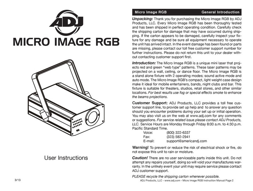
American DJ Micro Image RGB User manual

American DJ

American DJ Micro Image RGB User manual

American DJ Raider User manual

American DJ

American DJ Raider User manual

American DJ Pinspot LED User manual

American DJ

American DJ Pinspot LED User manual

American DJ Fun Factor LED User manual

American DJ

American DJ Fun Factor LED User manual

American DJ Quadra Force/Sys User manual

American DJ

American DJ Quadra Force/Sys User manual

American DJ Mega Pixel LED User manual

American DJ

American DJ Mega Pixel LED User manual

American DJ X-Treme/19C Installation instructions

American DJ

American DJ X-Treme/19C Installation instructions

American DJ Rolling Star User manual

American DJ

American DJ Rolling Star User manual

American DJ Theatrix PRO 48 LED User manual

American DJ

American DJ Theatrix PRO 48 LED User manual

American DJ Saturn Tri LED User manual

American DJ

American DJ Saturn Tri LED User manual

Popular Dj Equipment manuals by other brands

MAGMATIC Prisma Wash 25 user manual

MAGMATIC

MAGMATIC Prisma Wash 25 user manual

HERA PROCOLOR 60 RGBW SERIES User manual & installation guide

HERA

HERA PROCOLOR 60 RGBW SERIES User manual & installation guide

EuroLite LED TSL-600 SCAN COB user manual

EuroLite

EuroLite LED TSL-600 SCAN COB user manual

Ledj Slimline 12HEX12 user manual

Ledj

Ledj Slimline 12HEX12 user manual

Laserworld Garden GS-50RG Xmas manual

Laserworld

Laserworld Garden GS-50RG Xmas manual

Chauvet OVATION E-930VW Quick reference guide

Chauvet

Chauvet OVATION E-930VW Quick reference guide

Snow Masters Zig Oscillator user manual

Snow Masters

Snow Masters Zig Oscillator user manual

EuroLite 50530554 user manual

EuroLite

EuroLite 50530554 user manual

Beamz BUV243 user manual

Beamz

Beamz BUV243 user manual

Eagletone 6 Eyes Flower user manual

Eagletone

Eagletone 6 Eyes Flower user manual

EuroLite FLD-1508 user manual

EuroLite

EuroLite FLD-1508 user manual

Technical Pro LG8xSEA user manual

Technical Pro

Technical Pro LG8xSEA user manual

JB Systems Lounge Laser DMX Operation manual

JB Systems

JB Systems Lounge Laser DMX Operation manual

Elation FUZE WASH Z350 user manual

Elation

Elation FUZE WASH Z350 user manual

Maverick MK3 WASH Quick reference guide

Maverick

Maverick MK3 WASH Quick reference guide

Infinity TF-260C7 Fresnel manual

Infinity

Infinity TF-260C7 Fresnel manual

Chauvet EVE E-50Z Quick reference guide

Chauvet

Chauvet EVE E-50Z Quick reference guide

Eliminator Lighting E 138 manual

Eliminator Lighting

Eliminator Lighting E 138 manual

manuals.online logo
manuals.online logoBrands
  • About & Mission
  • Contact us
  • Privacy Policy
  • Terms and Conditions

Copyright 2025 Manuals.Online. All Rights Reserved.