Snow Masters Zig Oscillator User manual

Zig Oscillator
User Manual
256-229-5551
24-Hour Technical Support: 888-391-7669
www.snowmasters.com
Lifetime Warranty
© 2009 SnowMasters
Ver 1.0

2
Important information about your SnowMasters® Zig Oscillator machine, “the best os-
cillator in the world.”
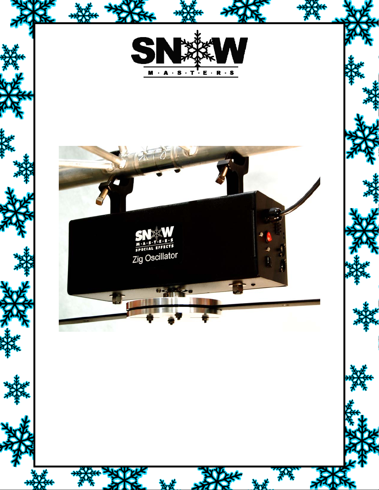
Congratulations on your purchase of this SnowMasters®Zig Oscillator. With your machine you
will dazzle and entertain audiences in large or small venues. Your Zig Oscillator is loaded with
advanced features, but at the same time it is very easy to use.
The Zig Oscillator is a modernized design in a family of special effects machines used for years in
Movie Productions, Theatres, Malls, and Presentations. This machine is designed to extend the
coverage of an average SnowMasters snow machine by 70%. This will reduce the need for multi-
ple machines in most scenarios. The 90 degree rotation of the oscillator gives you the perfect
coverage for almost any application. The clamps are superb for attaching to 2” trussing.
CAUTION:
YOU MUST READ THE FOLLOWING BEFORE OPERATING THE ZIG OSCILLATOR
The Zig Oscillator is an Electric Product – not a toy. To avoid the risk of fire, burns, personal in-
jury, and electric shock, it should not be played with and should be placed out of the
reach of small children. Adult supervision is continuously necessary to avoid the risk of electric
shock or personal injury. Never remove the covers or open the enclosures.
Always mount the Zig Oscillator using the two secured “C” clamps. Wrap a safety chain around
the yoke brackets for secondary protection.
Never leave the Zig Oscillator unattended while operating. Do not operate it in the rain or near
standing water. Always use an outlet with an earth grounding receptacle and a Ground Fault Cir-
cuit Interrupt (GFCI).
Never use this product for any activity other than for its intended use.
Features
• 4 – Channel DMX control
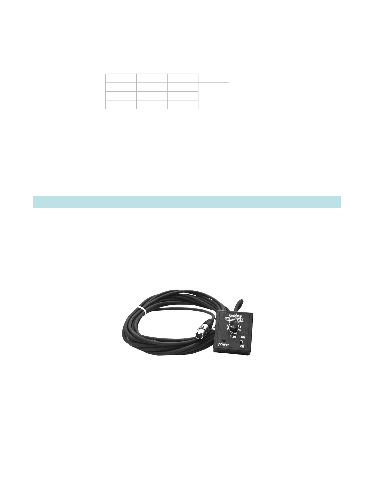
• Remote control (rented/sold separately)
• Variable stand alone features
• Lifetime warranty
• 24 – hour Technical service
• Repeat cycle timer ( 5min. and 15 min. cycles)
• Easy to install
• Works with most machines
• Extends effects coverage
• Factory set to 90 degrees rotation, can also be ordered set to 15 or 45 degrees
• SnowMasters standard C-clamps mounted to the top of the Zig Oscillator
• Bottom plate mounts to any of the SnowMasters standard hanging brackets
Welcome
**IMPORTANT PRODUCT AND SAFETY INFORMATION**
Failure to follow these instructions can cause serious bodily injury or property damage.
1.0 Zig Oscillator Features

3
Voltage: □110v □220V
Current: 100 Watts
Size: 16”l x 14”h x 6”w
Weight: 21.5 pounds
Weight Capacity: 75 pounds
Materials: 14 ga. Mild steel housing
Color: Black
Power Cable Length: 7 feet
Tether Length to Remote (Optional Accessory): 25 feet
Operating Instructions:
The Zig Oscillator has simple instructions that must be carefully followed in order to create the
desired effect, ensure the safety of the operators/participants and to protect the equipment from
damage.
PLEASE FOLLOW THESE INSTRUCTIONS CAREFULLY.
1) Once the Zig Oscillator is unpacked, find a suitable
location to mount it to the chosen SnowMasters®
machine bracket.
2) You will need an adjustable wrench or socket
wrench to loosen and tighten the bolts on the
Zig Oscillator bracket mounting plate(s). You
will want to ensure that the Center of Rota-
tion sticker (located on the top of the Zig Oscil-
lator bracket mounting plate) and the front of
the machine being attached are in the desired
direction before attaching the chosen machine.
Note: The Zig Oscillator works with the majority
of SnowMasters® machines.
2.0 Zig Oscillator Specifications
3.0 General Operating Instructions
Step 1—Unpack the Zig Oscillator
Step 2—Prepare to mount the Zig Oscillator to the desired machine

4
3) Remove the four nuts from the four bolts holding the
two Zig Oscillator bracket mounting plate(s) together.
Place the desired machine mounting bracket between
the two Zig Oscillator mounting plates, lining up the
four bolts around the machine mounting bracket
holes and re-attach and tighten all four nuts.
Machine bracket
4) Carefully lift both the machine and Zig Oscillator to its
desired mounting location. Depending on the height of
the desired effects location and machine weight, two or
more people may be required to assist.
Step 3—Mount the Zig Oscillator to the machine mounting bracket
Step 4—Mount the Zig Oscillator and machine to truss
Important:
Ensure all four nuts are tightened
and machine bracket is secured
before lifting.
Caution:
Use caution when lifting heavy
machines. Use machine handles
and/or C-clamps for lifting and/or
placement.
Important:
Ensure both C-clamps are securely
tightened. and the Zig Oscillator
mounting plate and machine are
parallel to floor and/or truss.

5
5) Connect the power cord from the Zig Oscillator.
If applicable, attach DMX-512 cable and/or Snow-
Masters® 25-foot Hard Wire Remote (rented/sold
separately).
The Zig Oscillator controller has DMX-512 capability and a remote
control interface. The machine is addressable by a three digit rotary
selection switch accessible from the side of the device. The DMX ad-
dress is settable in a decimal fashion. A handy Oscillator Thumb Dial
Settings label is attached to the back of the machine for quick refer-
ence.
The DMX interface is compliant with DMX-512 standards and electrically isolated to 1000VAC. The
start address is selectable from 1 to 509. The DMX protocol occupies 4 channel positions defined
as Mode, Cycle Time, Duration, and Speed. The Mode channel defines the overall operation of the
oscillator with modes defined as Off, On, and Momentary. The Mode Channel will correspond to
the selected start address*, with the Cycle Time, Duration, and Speed Channels following in or-
der.
When mode is set to one of the Momentary modes (5 or 15 min cycle), the Cycle Time and Dura-
tion variables shall become active and actuate the oscillator for relative times of the Cycle Time
and Duration DMX channel values. The Cycle Time has a rate ranging from 10 seconds to 5 min-
utes in the 5 minute cycle and 10 seconds to 15 minutes in the 15 minute cycle. The Duration
channel acts as a percentage of the total Cycle Time.
Step 4—Connect Power and DMX cable to the Zig Oscillator (if applicable)
Step 5— Set the Thumb Dial to DMX or Standalone mode
Mode Cycle Time Duration Speed
255 255 255 255
::::
0000
* Selected Start Address
255
:
192
191
:
128
127
:
64
63
:
0
Always On
15 Min Cycle
5 Min Cycle
Off

6
Thumb Dial Settings: The tables below show the all settings that can be attained with the use of
the 3 rotary switches located on the back of the device. An ‘X’ in a position indicates that the
number in that position does not matter for the required result to be attained. Switch A is in the
hundreds position, Switch B is in the tens position, and Switch C is in the ones position.
Tables 2 and 3 show what occurs in the Momentary 5 minute and 15 minute cycle states. Within
these states the device cycles on and off based on the B switch setting. The cycle time is the total
time between cycles and the “on time” is the time during that cycle when the device is running. It
is in an idle, wait state otherwise.
Table 4 shows the use of switch C during one of the Momentary cycle states (Switch A is 6 or 7).
Switch C controls the speed as a percentage of total speed.
A B C State
000 Idle
001
:::
509
510
:::
599
6XX5MinCycle
7 X X 15 Min Cycle
8XXAlwaysOn
9XXRemote
DMX
Idle
Table 1
Table 1 shows that there are six states in
which the device may operate: Idle, DMX, 5
minute cycle, 15 minute cycle, always on, and
remote.
ABCOnTime
60X25SecOn
61X50SecOn
62X75SecOn
63X100SecOn
64X125SecOn
65X150SecOn
66X175SecOn
67X200SecOn
68X225SecOn
69X250SecOn
Table 2
ABCOnTime
70X75SecOn
7 1 X 150 Sec On
7 2 X 225 Sec On
7 3 X 300 Sec On
7 4 X 375 Sec On
7 5 X 450 Sec On
7 6 X 525 Sec On
7 7 X 600 Sec On
7 8 X 750 Sec On
7 9 X 825 Sec On
Table 3
A B C Speed
6,7 X 0 Speed %
6,7 X 1 Speed %
6,7 X 2 Speed %
6,7 X 3 Speed %
6,7 X 4 Speed %
6,7 X 5 Speed %
6,7 X 6 Speed %
6,7 X 7 Speed %
6,7 X 8 Speed %
Table 4

7
Optional Remote Control Accessory
Table 5 shows the use of switches B and C when switch A is set to 8 (Always on state). Switches
B and C work similarly to Switch C when Switch A is set to either 6 or 7 (Momentary states), in
that it controls the speed as a percentage of the total speed. This enables the user more precise
speed control.
The DMX interface is also provided as a pass thru connection. The remote interface attempts to
use the standard pin 2 and 3 of the XLR5 connector to supply power to the remote control. Pins 4
and 5 are pass thru when used in a DMX configuration. Pins 4 and 5 have power applied to them
only when the DMX selector is set to the 900s and this power is used to power the remote.
Note: The user should avoid configuring the A selector to the 9 position while the DMX connection
is being used.
The remote control interface is available as an optional accessory item (ordered separately). The
remote control provides a 25-foot tethered, connection to the Oscillator machine. The only control
the remote has is on and off and speed. The speed knob shall be notched to provide 5 distinct set-
tings, Off, 1 – 4. There is also a status led to inform the user that the unit is on and powered. It
also flashes to show the status of operation; the 3 rotary switches must be at 900 for remote
function to be enabled. When the unit is powered and the Speed knob is set to the Off position the
red LED with flash constantly to tell the user that the unit is in standby. When the user turns the
knob to another setting the LED will go to a solid red.
Optional accessory item.
A B C Speed
800
:::
899
Speed %
Table 5

8
Limited Lifetime Warranty
SnowMasters Offices—The World Leader in Special Effects
Locations:
U.S. East Coast
U.S. West Coast
Australia
France
Germany
Italy
Japan
Spain
The Netherlands
U.K. / Ireland
More on the way...
Mailing Address:
11054 County Rd 71
P.O. Box 250
Lexington, AL 35648
Phone:
(256) 229-5551
Fax:
(256) 229-5552
24 Hour Tech Support
888-391-7669
On the Web:
www.snowmasters.com
Email:
The SnowMasters Family:
Each SnowMasters®Zig Oscillator machine comes with this limited, lifetime warranty
from any manufacturing defects, providing the following criteria are met:
- The machine has not been attached to a non-SnowMasters device.
- The machine has not exceeded its weight capacity.
- The machine has not been dropped, misused or abused.
- The machine has not been disassembled in any way.
Having met these criteria any SnowMasters® Zig Oscillator that fails to work during normal
operations will be serviced and/or replaced with another Zig Oscillator. It is the responsibility of
the customer to incur the costs of shipping the machine to and from SnowMasters for repair or
replacement. Upon receiving the machine, it will be at SnowMasters sole discretion as to whether
all warranty criteria have been met.
SnowMasters®is not responsible for loss of income, labor, or business as a result of a Zig
Oscillator malfunction. SnowMasters®is not responsible for physical damage or scratching damage
after shipping from SnowMasters®Manufacturing facility. For safety reasons, SnowMasters®will
repair damaged electrical wires per the warranty. There is a lifetime warranty on the circuit board
and other electronics to the oscillator.
The customer must fill out a Repair Return Form, which is included in the user manual. This
form is also available for download at www.snowmasters.com or by calling (256) 229-5551 to
receive by mail or fax. We will do everything possible to address your machine concerns
promptly and efficiently. Also ask about our optional Warranty Replacement Program.

9
Company Name: ____________________ Prepared by: _______________________
Contact Name: ______________________ Today's Date: ___ / ___ / ______
Phone Number : ____________________ Return by Date: ___ / ___ / ______
Item(s) being returned Serial Number Description of Problem
______________________ _________________ ________________________
______________________ _________________ ________________________
______________________ _________________ ________________________
Return Shipping Address:
Street Address: _________________________________________________________________
City: ________________________________________ State: ______ Zip Code:____________
Attention: ____________________________________
Shipping Company for SnowMasters to use: UPS ___ Fedex ___ Other (List):_______________
Account #: ___________________
Ship repair returns to:
SnowMasters
11054 County Road 71
Lexington, AL 35648
256-229-5551 phone
256-229-5552 fax
www.snowmasters.com
Machine Type: ________________________ Serial Number: ________________________
Date Received: ___ / ___ / ______ Date Returned: ___ / ___ / ______
Problem Identification: __________________________________________________
_____________________________________________________________________
_____________________________________________________________________
Time Repair began: __________ am / pm Time Repair Finished: _________ am / pm
Total Repair Time: ______ hrs ______ mins
Work Performed: _______________________________________________________
_____________________________________________________________________
_____________________________________________________________________
Technician: ______________________________ Date: ___ / ___ / ______
REPAIR RETURN FORM
REPAIR REPORT (SNOWMASTERS USE ONLY)
Table of contents
Other Snow Masters Dj Equipment manuals

Snow Masters
Snow Masters T1600 User manual

Snow Masters
Snow Masters SNOW ZONE User manual

Snow Masters
Snow Masters T-1500 Mini User manual

Snow Masters
Snow Masters T-1000 User manual

Snow Masters
Snow Masters holey smokes User manual

Snow Masters
Snow Masters Inflatable Snowman User manual

Snow Masters
Snow Masters T-5000 User manual
Popular Dj Equipment manuals by other brands

Schnick-Schnack-Systems
Schnick-Schnack-Systems DMX Player user manual

Flash professional
Flash professional P7100462 user manual

Electra Light
Electra Light Big Bubble Machine manual

Briteq
Briteq BT-PROFILE HD Operation manual

American DJ
American DJ DJ Roller User instructions

GLP
GLP IMPRESSION X4L instruction manual