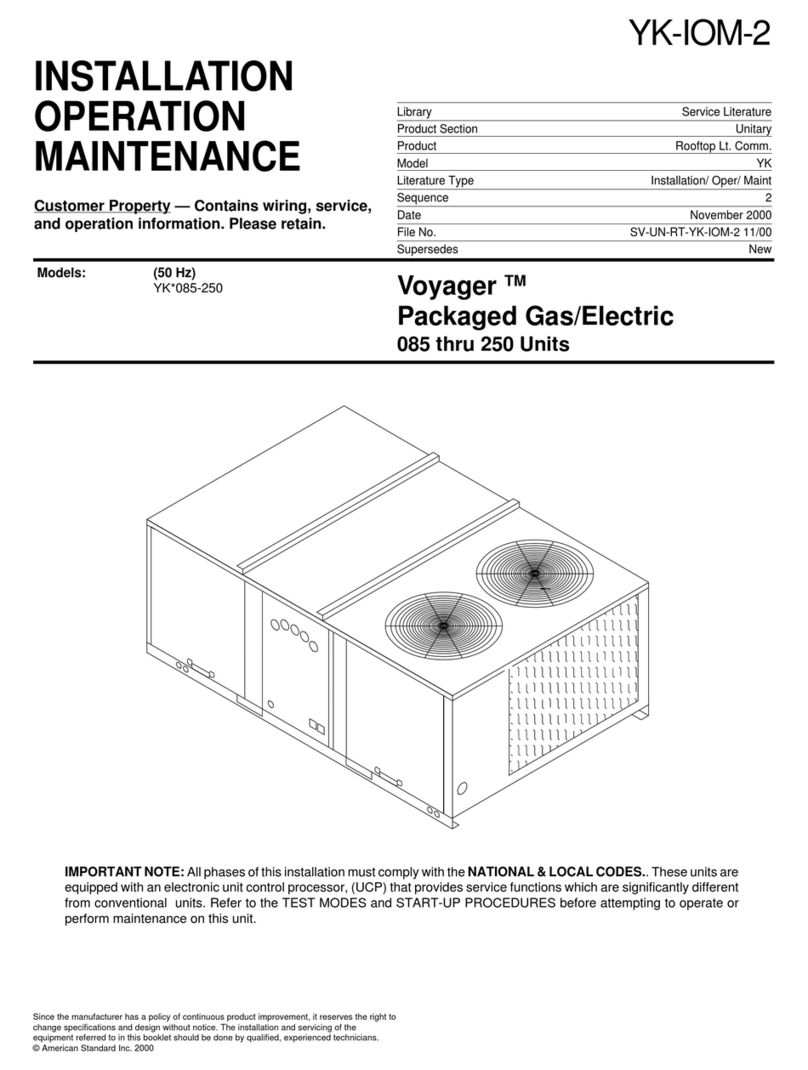
American Standard YC 100B Series Owner's manual

YC-IOM-12
18-EB60D14
Library Service Literature
Product Section Unitary
Product Rooftop Lt. Comm.
Model YC
Literature Type Installation/ Oper/ Maint
Sequence 12
Date October 2001
File No. SV-UN-RT-YC-IOM-12 10/01
Supersedes New
Since the manufacturer has a policy of continuous product improve-
ment, it reserves the right to change specifications and design without
notice. The installation and servicing of the equipment referred to in this
booklet should be done by qualified, experienced technicians.
© American Standard Inc. 2001
Models:
YC*150 - 301 (60 Hz)
YC*125 - 250 (50 Hz)
INSTALLATION
OPERATION
MAINTENANCE
Customer Property — Contains wiring, service,
and operation information. Please retain.
Packaged Gas Electric
12-1/2 Thru 25 Ton
IMPORTANT NOTE: All phases of this installation must comply with the NATIONAL, STATE & LOCAL CODES. In
addition to local codes, the installation must conform with National Electric Code -ANSI/NFPA NO. 70 LATEST
REVISION. These units are equipped with an electronic unit control processor, (UCP) that provides service functions
which are significantly different from conventional units. Refer to the TEST MODES and START-UP PROCEDURES
before attempting to operate or perform maintenance on this unit.

2
Table of Contents
Literature Change History ........................................... 3
Unit Description........................................................... 4
Standard Controls Description .................................... 4
System Input Devices & Functions ............................. 4
Unit Inspection ............................................................ 6
Unit Clearances .......................................................... 6
Unit Dimensions & Weight Information ....................... 7
Roof Curb.................................................................. 10
Rigging .......................................................................11
General Unit Requirements........................................11
Factory Installed Economizer.................................... 12
Return Air Smoke Detector ....................................... 12
Main Electrical Power Requirements ........................ 12
Low Voltage Wiring (AC & DC) Requirements .......... 12
Requirements for Gas Heat ...................................... 12
Condensate Drain Connection .................................. 12
Filter Installation ........................................................ 13
Field Installed Power Wiring...................................... 13
Main Unit Power Wiring ............................................ 13
Field Installed Control Wiring .................................... 14
Controls using DC Analog Input/Outputs .................. 14
Controls using DC Communication Links ................. 14
Space Temperature Averaging .................................. 18
Pre-Installation Checklist........................................... 21
Voltage Imbalance..................................................... 21
Electrical Phasing ..................................................... 22
Compressor Crankcase Heaters............................... 22
UnitStart-up .............................................................. 23
Test Modes................................................................ 23
UnitStart-up .............................................................. 25
Verifying Proper Air Flow........................................... 25
Return Air Smoke Detector ....................................... 25
Economizer Start-Up ................................................. 25
UnitStart-up .............................................................. 26
CompressorStart-Up ................................................ 26
Gas Heat Units.......................................................... 26
Final System Setup ................................................... 27
Fan Belt Adjustment .................................................. 27
Maintenance ............................................................. 28
Monthly Maintenance ................................................ 28
Filters ........................................................................ 28
Return Air Smoke Detector Maintenance.................. 28
Cooling Season......................................................... 28
Heating Season ........................................................ 28
Coil Cleaning............................................................. 29
System Status Checkout Procedure ......................... 31
Trouble Shooting ....................................................... 32
Service Failure .......................................................... 32
Simultaneous Heat and Cool Failure ........................ 32
System Failure .......................................................... 32
Heat Failure .............................................................. 32
Cool Failure............................................................... 32
Service Failure .......................................................... 32

3
Literature Change History
YC-IOM-12 (October 2001)
First issue of manual; provides Installation, Operation, and
Maintenance instructions for 12-1/2 through 25 Ton pack-
aged gas/electric units.
Overview of Manual
Note: One copy of this document ships inside the
control panel of each unit and is customer property.
It must be retained by the unit’s maintenance
personnel.
This booklet describes proper installation, operation, and
maintenance procedures for air cooled systems. By carefully
reviewing the information within this manual and following
the instructions, the risk of improper operation and/or compo-
nent damage will be minimized.
It is important that periodic maintenance be performed to
help assure trouble free operation. A maintenance schedule
is provided at the end of this manual. Should equipment fail-
ure occur, contact a qualified service organization with quali-
fied, experienced HVAC technicians to properly diagnose
and repair this equipment.
Note: Do Not release refrigerant to the atmosphere!
If adding or removing refrigerant is required, the
service technician must comply with all federal,
state, and local laws.
General Information
Model Number Description
All products are identified by a multiple-character model
number that precisely identifies a particular type of unit. An
explanation of the alphanumeric identification code is pro-
vided below. Its use will enable the owner/operator, installing
contractors, and service engineers to define the operation,
specific components, and other options for any specific unit.
When ordering replacement parts or requesting service, be
sure to refer to the specific model number and serial number
printed on the unit nameplate.

4
General Information
Unit Nameplate
A Mylar unit nameplate is located on the unit’s corner
support just above the main power entrance access into the
control panel. It includes the unit model number, serial
number, electrical characteristics, refrigerant charge, as well
as other pertinent unit data.
Compressor Nameplate
The nameplate for the compressors are located on the com-
pressor terminal box.
Hazard Identification
Warnings are provided throughout this manual to indi-
cate to installing contractors, operators, and service
personnel of potentially hazardous situations which, if
not avoided, COULD result in death or serious injury.
Cautions are provided throughout this manual to indi-
cate to installing contractors, operators, and service
personnel of potentially hazardous situations which, if
not avoided, MAY result in minor or moderate injury.
Unit Description
Before shipment, each unit is leak tested, dehydrated,
charged with refrigerant and compressor oil, and run tested
for proper control operation.
The condenser coils are aluminum fin, mechanically bonded
to copper tubing.
Direct-drive, vertical discharge condenser fans are provided
with built-in thermal overload protection.
Standard Controls Description
Standard controls for these units is a microelectronic control
system that is referred to as “Unit Control Processor” (UCP).
The acronym UCP is used extensively throughout this docu-
ment when referring to the control system network.
These modules through Proportional/Integral control algo-
rithms perform specific unit functions that governs unit op-
eration in response to; zone temperature, supply air tem-
perature, and/or humidity conditions depending on the appli-
cation. The stages of capacity control for these units is
achieved by starting and stopping the compressors.
The UCP is mounted in the control panel and is factory wired
to the respective internal components. The UCP receives
and interpret information from other unit modules, sensors,
remote panels, and customer binary contacts to satisfy the
applicable request for cooling.
UEM - Unit Economizer Module (Optional)
The UEM monitors the supply air temperature, return air
temperature, minimum position setpoint (local or remote),
power exhaust setpoint, ambient dry bulb/enthalpy sensor or
comparative humidity (return air humidity against ambient
humidity) sensors, if selected, to control the dampers to an
accuracy of +/- 5% of the stroke. The actuator is spring re-
turned to the closed position any time power is lost to the
unit. It is capable of delivering up to 25 inch pounds of torque
and is powered by 24 VAC. Refer to the sequence of opera-
tion “Cooling with an Economizer” for the proper DIP Switch
settings for dry bulb/Enthalpy control.
CTI - Conventional Thermostat Interface (Optional)
This module is a field installed option to allow some conven-
tional thermostats to be used in conjunction with the. It uti-
lizes the conventional wiring scheme of R, Y1, Y2, W1, W2/
X, and G.
Applicable thermostats to be used with the CTI module are:
Vendor Part # Trane Part #
Honeywell T7300
Honeywell T874D1082 BAYSTAT011
Enerstat MS-1N BAYSTAT003
TCI - Trane Communication Interface (Optional)
This module is used when the application calls for either an
ICSTM building management type control system and/or a
High Temperature limit device. It allows the control and moni-
toring of the system through an ICS panel. The module can
be ordered from the factory or ordered as a kit to be field in-
stalled. Follow the installation instruction that ship with each
kit when field installation is necessary.
System Input Devices & Functions
The UCP must have a mode input in order to operate the
rooftop unit. The flexibility of having several mode capabili-
ties depends upon the type of sensor and/or remote panel
selected to interface with the UCP. The possibilities are: Fan
selection ON or AUTO. System selection HEAT, COOL,
AUTO, and OFF.
The descriptions of the following basic Input Devices used
within the UCP network are to acquaint the operator with
their function as they interface with the various modules. Re-
fer to the unit’s electrical schematic for the specific module
connections.
The following controls are available from the factory for field
installation.
Supply Fan Failure Input (Optional)
The Fan Failure Switch can be connected Actively or Pas-
sively to sense indoor fan operation:
Passive - FFS (Fan Failure Switch) When the fan proving
switch is connected to the Fan/Filter Status terminal (J5-1)
on the UCP, if air flow through the unit is not proven by
the differential pressure switch (factory set point 0.05 “
w.c.) within 40 seconds nominally, the UCP will energize
the clogged filter output and the LED at the remote panel
will be turned “On”.

5
General Information
Active - AFF (Active Fan Failure) When the fan proving
switch is connected across terminals J5-3 & J5-4 on the
unit economizer module (UEM), if air flow through the unit
is not proven by the differential pressure switch (factory
set point 0.05 “ w.c.) within 40 seconds nominally, the
UCP will shut off all mechanical operations, lock the sys-
tem out, send a diagnostic to ICS, and the SERVICE LED
will flash. The system will remain locked out until a reset
is initiated either manually or through ICS.
Clogged Filter Switch (Optional)
The unit mounted clogged filter switch monitors the pressure
differential across the return air filters. It is mounted in the fil-
ter section and is connected to the UCP. A diagnostic SER-
VICE signal is sent to the remote panel if the pressure differ-
ential across the filters is at least 0.5" w.c.. The contacts will
automatically open when the pressure differential across the
filters decreases to approximately 0.4" w.c.. The switch dif-
ferential can be field adjusted between 0.17" w.c. to 5.0" w.c.
± 0.05" w.c. to correspond to the desired dirty filter condition.
The clogged filter output is energized when the supply fan is
operating and the clogged filter switch has been closed for at
least 2 minutes. The system will continue to operate regard-
less of the status of the filter switch.
Compressor Disable (CPR1/2)
This input incorporates the low pressure control (LPC) of
each refrigeration circuit and can be activated by opening a
field supplied contact installed in series with the LPC.
If this circuit is open before the compressor is started, the
compressor will not be allowed to operate. Anytime this cir-
cuit is opened for 5 continuous seconds during compressor
operation, the compressor for that circuit is immediately
turned “Off”. The compressor will not be allowed to restart for
a minimum of 3 minutes should the LPC close.
If four consecutive open conditions occur during the first
three minutes of operation, the compressor for that circuit will
be locked out, a diagnostic communicated to the remote
panel (if installed), and a manual reset will be required to re-
start the compressor.
Low Pressure Control
This input incorporates the low pressure and can be acti-
vated by opening a field supplied contact.
Anytime this circuit is opened for 5 continuous seconds, the
compressor for that circuit is turned off immediately. The
compressor will not be allowed to restart for a minimum of 3
minutes.
If four consecutive open conditions occur during the first
three minutes of operation, the compressor will be locked
out, a diagnostic communicated to ICSTM if applicable, and a
manual reset will be required to restart the compressor.
High Pressure Control
The high pressure controls are wired in series between the
compressor outputs on the UCP and the compressor
contactor coils. If the high pressure control switch opens, the
UCP senses a lack of current while calling for cooling and
locks the compressor out.
On dual circuit units, if the high pressure control opens, the
compressor on the affected circuit is locked out. Amanual re-
set for the affected circuit is required.
Power Exhaust Control (Optional)
The power exhaust fan is started whenever the position of
the economizer dampers meets or exceed the power ex-
haust set point when the indoor fan is on.
The set point panel is located in the return air section and is
factory set at 25%.
Lead/Lag Control (Dual Circuit Only)
Lead/Lag is a selectable input located on the UCP. The UCP
is configured from the factory with the Lead/Lag control dis-
abled. To activate the Lead/Lag function, simply cut the wire
(52F) connected to J1-7 at the UCP. When it is activated,
each time the designated lead compressor is shut off due to
the load being satisfied, the lead compressor or refrigeration
circuit switches. When the UCP is powered up, i.e. after a
power failure, the control will default to the number one cir-
cuit compressor.
Remote Zone Sensor (BAYSENS016A)
This bullet type temperature sensor can be used for; outside
air (ambient) sensing, return air temperature sensing, supply
air temperature sensing, remote temperature sensing (un-
covered. Wiring procedures vary according to the particular
application and equipment involved. Refer to the unit’s wiring
diagrams for proper connections.
Remote Zone Sensor (BAYSENS017B)
This electronic sensor can be used with BAYSENS006B,
008B, 010B, 019A, 020A, or 021A Remote Panels. When
this sensor is wired to a BAYSENS019A or BAYSENS020A
Remote Panel, wiring must be 18 AWG Shielded Twisted
Pair (Belden 8760 or equivalent). Refer to the specific Re-
mote Panel for wiring details.

6
General Information
Unit Inspection
As soon as the unit arrives at the job site
[ ] Verify that the nameplate data matches the data on the
sales order and bill of lading (including electrical data).
[ ] Verify that the power supply complies with the unit name-
plate specifications.
[ ] Visually inspect the exterior of the unit, including the roof,
for signs of shipping damage.
[ ] Check for material shortages. Refer to the Component
Layout and Shipwith Location illustration.
PRODUCT CONTAINS FIBERGLASS WOOL!
Disturbing the Insulation in this product during in-
stallation, maintenance or repair will expose you to
airborne particles of glass wool fibers and ceramic
fibers known to the state of California to cause can-
cer through inhalation. Glasswool fibers may also
cause respiratory, skin or eye irritation.
Precautionary Measures
-Avoid breathing fiberglass dust.
-Use a NIOSH approved dust/mist respirator.
-Avoid contact with the skin or eyes. Wear long-
sleeved, loose-fitting clothing, gloves, and eye
protection.
-Wash clothes separately from other clothing:
rinse washer thoroughly.
-Operations such as sawing, blowing, tear-out, and
spraying may generate fiber concentrations requiring
additional respiratory protection. Use the appropriate
NIOSH approved respiration in these situations.
First Aid Measures
Eye Contact - Flush eyes with water to remove
dust. If symptoms persist, seek medical attention.
Skin Contact - Wash affected areas gently with soap
and warm water after handling.
If the job site inspection of the unit reveals damage or mate-
rial shortages, file a claim with the carrier immediately.
Specify the type and extent of the damage on the “bill of lad-
ing” before signing.
[ ] Visually inspect the internal components for shipping dam-
age as soon as possible after delivery and before it is
stored. Do not walk on the sheet metal base pans.
NO STEP SURFACE!
FOR ACCESS TO COMPONENTS, THE BASE SHEET
METAL SURFACE MUST BE REINFORCED.
Bridging between the unit's main supports may
consist of multiple 2 by 12 boards or sheet metal
grating.
Failure to comply can cause severe personal injury or
death from falling.
[ ] If concealed damage is discovered, notify the carrier’s ter-
minal of damage immediately by phone and by mail. Con-
cealed damage must be reported within 15 days.
Request an immediate joint inspection of the damage by
the carrier and the consignee. Do not remove damaged
material from the receiving location. Take photos of the
damage, if possible. The owner must provide reasonable
evidence that the damage did not occur after delivery.
[ ] Notify the appropriate sales representative before install-
ing or repairing a damaged unit.
Storage
Take precautions to prevent condensate from forming inside
the unit’s electrical compartments and motors if:
a. the unit is stored before it is installed; or,
b. the unit is set on the roof curb, and temporary heat is
provided in the building. Isolate all side panel service
entrances and base pan openings (e.g., conduit
holes, S/A and R/A openings, and flue openings) from
the ambient air until the unit is ready for startup.
Note: Do not use the unit’s heater for temporary
heat without first completing the startup procedure
detailed under “Starting the Unit”.
The manufacturer will not assume any responsibility for
equipment damage resulting from condensate accumulation
on the unit’s electrical and/or mechanical components.
Unit Clearances
Figure 3-1 illustrates the minimum operating and service
clearances for either a single or multiple unit installation.
These clearances are the minimum distances necessary to
assure adequate serviceability, cataloged unit capacity, and
peak operating efficiency.
Providing less than the recommended clearances may result
in condenser coil starvation, “short-circuiting” of exhaust and
economizer airflows, or recirculation of hot condenser air.

7
General Information
Unit Dimensions & Weight Information
Overall unit dimensional data for each unit is illustrated in Fig-
ure 3-2.
A Center-of-Gravity illustration and the dimensional data is
shown in Figure 3-5.
Table 3-1 lists the typical unit operating and point loading
weights.
Figure 3-1
Typical Installation Clearances for Single & Multiple Unit
Applications

8
General Information
Figure 3-2
Unit Dimensional Data
UNITS A B C D E F G H J K
YC*100B 63-5/16 93 -3/4 13/16 49 25 -5/8 2 -3/16 8 -3/8 44 -15/16 51 -5/16 2
YC*125C 49 63-5/16 94-5/16 39-3/8 6-13/16 13/16 8-3/8 2-3/16 28-5/8 2
YC*150D,151C 50-1/8 71-5/16 107-5/16 48-3/8 6-5/8 13/16 8-3/8 2-11/16 29-5/16 2
YC*155B,175C
YC*180B,210C
YC*181C,200B 54 85-5/16 122-5/16 64-1/2 6-13/16 13/16 8-15/16 2-11/16 33-3/16 3
YC*211C,240B
YC*241C,250B
YC*300B,301C
* Downflow orHorizontal

9
General Information
Table 3-1
Typical Unit Weights & Point Loading Data
Unit Net Corner Wts. (lbs)
ModelsWeightABCD
YC*100B 1247 425 331 215 276
YC*125C 1300 430 342 234 294
YC*150D 1458 495 373 254 336
YC*151C 1547 523 383 271 370
YC*155B 1538 535 387 259 357
YC*180B 1665 600 395 266 404
YC*181C 2005 686 504 345 470
YC*175C 1619 553 415 279 372
YC*210C 1821 618 463 317 424
YC*211C 2088 701 538 369 480
YC*200B 2025 714 532 333 447
YC*240B 2088 738 526 343 481
YC*241C 2186 751 568 373 494
YC*250B 2082 721 552 351 458
YC*300B 2082 721 552 351 458
YC*301C 2191 755 569 373 495
* Downflow or Horizontal
Note: Corner weights are given for information only.
Unitis to be supported continuouslybya curb or
equivalentframe support.
Foundation
Horizontal Units
If the unit is installed at ground level, elevate it above the
snow line. Provide concrete footings at each support location
with a “full perimeter” support structure or a slab foundation
for support. Refer to Table 3-1 for the unit’s operating and
point loading weights when constructing a footing foundation.
Anchor the unit to the slab using hold down bolts or isolators.
Isolators should be installed to minimize the transmission of
vibrations into the building.
For rooftop applications, ensure the roof is strong enough to
support the combined unit and support structural weight. Re-
fer to Table 3-1 for the unit operating weights. Anchor the unit
to the roof with hold-down bolts or isolators.
Check with a roofing contractor for proper waterproofing pro-
cedures.
Ductwork
Figure 3-3 illustrates the supply and return air openings as
viewed form the rear of the unit. Refer to Table 3-2 for the
unit opening dimensional data.
Elbows with turning vanes or splitters are recommended to
minimize air noise due to tubulance and to reduce static
pressure. The first elbow in the ductwork leaving the unit
should be downstream of the supply air opening at least 3-1/
2 times the diameter of the supply fan.
When attaching the ductwork to the unit, provide a water
tight flexible connector at the unit to prevent operating
sounds from transmitting through the ductwork.
All outdoor ductwork between the unit and the structure
should be weather proofed after installation is completed.
Figure 3-3
Horizontal Unit Supply & Return Air Openings

10
General Information
Table 3-2
Horizontal Unit Supply & Return Air Opening Dimensional Data
UNITS A B C D E F G H
YCH100B 22-1/2 18 17-3/16 2 3-15/16 41-7/16 16
YCH125C
YCH150D,151C 26-1/2 19-9/16 24-9/16 2 3-15/16 42-1/2 6
YCH155B,180B
YCH175C,210C
YCH181C,200B 26-1/2 24-1/16 27-9/16 2 3-15/16 46-7/16 5-3/8
YCH211C,240B
YCH241C,250B
YCH300B,301C
Roof Curb
Downflow
The roof curbs for these units consists of a “full perimeter”
enclosure to support the unit.
Before installing any roof curb, verify;
1. That it is the correct curb for the unit,
2. That it includes the necessary gaskets and
hardware,
3. That the purposed installation location provides
the required clearance for proper operation.
4. Insure that the curb is level and square. The top
surface of the curb must be true to assure an
adequate curb-to-unit seal.
Step-by-step curb assembly and installation instructions ship
with each accessory roof curb kit. Follow the instructions
carefully to assure proper fit-up when the unit is set into
place.
Note: To assure proper condensate flow during
operation, the unit (and curb) must be as level as
possible.
If the unit is elevated, a field constructed catwalk around the
unit is strongly recommended to provide easy access for unit
maintenance and service.
Recommendations for installing the Supply Air and Return
Air ductwork joining the roof curb are included in the curb in-
struction booklet. Curb ductwork must be fabricated and in-
stalled by the installing contractor before the unit is set into
place.
Note: For sound consideration, cut only the holes in
the roof deck for the ductwork penetrations. Do not
cut out the entire roof deck within the curb
perimeter.
If a Curb Accessory Kit is not used:
a. The ductwork can be attached directly to the factory-
provided flanges around the unit’s supply and return
air openings. Be sure to use flexible duct connections
at the unit.
b. For “built-up” curbs supplied by others, gaskets must
be installed around the curb perimeter flange and the
supply and return air opening flanges.
Ductwork
Figure 3-4 illustrates the supply and return air openings as
viewed form the top of the unit. Refer to Table 3-3 for the unit
opening dimensional data.
Elbows with turning vanes or splitters are recommended to
minimize air noise due to tubulance and to reduce static
pressure. The first elbow in the ductwork leaving the unit
should be downstream of the supply air opening at least 3-1/
2 times the diameter of the supply fan.
Figure 3-4
Downflow Unit Supply & Return Air Openings

11
General Information
Table 3-3
Downflow Unit Supply & Return Air Opening Dimensional Data
UNITSABCDEFGHJDrain
YCD100B 22-7/16 14-1/2 17-11/16 4-1/4 —4-1/4 54-13/16 47-3/16 24-5/8 1 NPT
YCD125C
YCD150D
YCD151C
YCD155B 26-7/16 22-1/2 18-11/16 4-1/4 —4-1/4 62-7/16 54-11/16 25-5/8 1 NPT
YCD175C
YCD180B
YCD210C
YCD181C
YCD200B
YCD211C
YCD240B 26-7/16 28-3/4 19-15/16 4-1/4 —4-1/4 76-5/16 68-11/16 26-3/4 1 NPT
YCD241C
YCD250B
YCD300B
YCD301C
Rigging
A Rigging illustration and Center-of-Gravity dimensional data
table is shown in Figure 3-5. Refer to the typical unit operat-
ing weights table before proceeding.
1. Remove the shipping crate from around the unit. Do not
remove the crating from the top of the unit as illustrated in
Figure 3-5.
2. Rig the unit as shown in Figure 3-5. Attach adequate
strength lifting slings to all four lifting brackets in the unit
base rail. Do not use cables, chains, or slings except as
shown.
3. Install a lifting bar, as shown in Figure 3-5, to protect the
unit and to facilitate a uniform lift. The minimum distance
between the lifting hook and the top of the unit should be
7 feet.
4. Test-lift the unit to ensure it is properly rigged and bal-
anced, make any necessary rigging adjustments.
5. Lift the unit and position it into place.
6. Downflow units; align the base rail of the unit with the curb
rail while lowering the unit onto the curb. Make sure that
the gasket on the curb is not damaged while positioning
the unit.
Unit Gravity (in.)
Models Length Width
YC*125C 42 26
YC*150D 46 29
YC*151C 45 30
YC*155B 45 29
YC*180B 43 29
YC*181C 52 35
YC*175C 46 29
YC*210C 46 29
YC*211C 53 35
YC*200B 52 33
YC*240B 51 34
YC*241C 53 34
YC*250B 53 33
YC*300B 53 33
YC*301C 53 34
* Downflow orHorizontal
Figure 3-5
General Unit Requirements
The checklist listed below is a summary of the steps required
to successfully install a commercial unit. This checklist is in-
tended to acquaint the installing personnel with what is re-
quired in the installation process. It does not replace the de-
tailed instructions called out in the applicable sections of this
manual.
[ ] Check the unit for shipping damage and material short-
age; file a freight claim and notify appropriate sales repre-
sentative.
[ ] Verify that the installation location of the unit will provide
the required clearance for proper operation.

12
General Information
[ ] Assemble and install the roof curb (if applicable). Refer to
the latest edition of the curb installers guide that ships
with each curb kit.
[ ] Fabricate and install ductwork; secure ductwork to curb.
[ ] Install pitch pocket for power supply through building roof.
(If applicable)
[ ] Rigging the unit.
[ ] Set the unit onto the curb; check for levelness.
[ ] Ensure unit-to-curb seal is tight and without buckles or
cracks.
[ ] Install and connect a condensate drain line to the evapo-
rator drain connection.
Factory Installed Economizer
[ ] Ensure the economizer has been pulled out into the oper-
ating position. Refer to the economizer installers guide for
proper position and setup.
[ ] Ensure the barometric relief damper has been properly as-
sembled and installed. (Units without Smoke Detectors)
Units with smoke detectors refer to the FIOP installation
literature before continuing with the economizer setup.
[ ] Install all access panels.
Return Air Smoke Detector
[ ] If this unit is equipped with an economizer, it will be neces-
sary for the installer to complete the hook-up of the return
air smoke detector. To complete this hook-up, refer to the
step-by-step procedure in the installation instructions for
the return air smoke detector provided in the literature
package.
Main Electrical Power Requirements
[ ] Verify that the power supply complies with the unit name-
plate specifications.
[ ] Inspect all control panel components; tighten any loose
connections.
[ ] Connect properly sized and protected power supply wiring
to a field-supplied/installed disconnect switch and to the
main power terminal block (HTB1) in the unit control
panel.
[ ] Install proper grounding wires to an earth ground.
Note: All field-installed wiring must comply with
NEC and applicable local codes.
Electric Heat Requirements
[ ] Verify that the power supply complies with the electric
heater specifications on the unit and heater nameplate.
[ ] Inspect the heater junction box and control panel; tighten
any loose connections.
[ ] Check electric heat circuits for continuity.
Low Voltage Wiring (AC & DC) Requirements
[ ] Install the zone thermostat, with or without switching sub-
base.
[ ] Connect properly sized control wiring to the proper termi-
nation points between the zone thermostat and the unit
control panel.
Requirements for Gas Heat
[ ] Gas supply line properly sized and connected to the unit
gas train.
[ ] All gas piping joints properly sealed.
[ ] Drip leg Installed in the gas piping near the unit.
[ ] Gas piping leak checked with a soap solution. If piping
connections to the unit are complete, do not pressurize
piping in excess of 0.50 psig or 14 inches w.c. to prevent
component failure.
[ ] Main supply gas pressure adequate.
[ ] Flue Tubes clear of any obstructions.
Condensate Drain Connection
An evaporator condensate drain connection is provided on
each unit. On horizontal units, the drain connection may be
located on the opposite side of the unit from the evaporator
access panel or on the corner of the unit next to the evapora-
tor access panel. Refer to Figure 3-3 for the appropriate
drain location.
On downflow units, the drain connection may be located on
either side of the unit depending on unit size. Refer to Figure
3-4 for the appropriate drain location.
A condensate trap must be installed at the unit due to the
drain connection being on the “negative pressure” side of the
fan. Install the P-Traps using the guidelines in Figure
3-6. On units with multiple drain connections, plug the un-
used connection before operating the unit.
A condensate drain line must be connected to P-Trap. Pitch
the drain lines at least 1/2 inch for every 10 feet of horizontal
run to assure proper condensate flow. Do not allow the hori-
zontal run to sag causing a possible double-trap condition
which could result in condensate backup due to “air lock”.

13
General Information
Figure 3-6
Condensate Trap Installation
Filter Installation
Each unit ships with two inch filters. The quantity of filters is
determined by unit size. Access to the filters is obtained by
removing the indoor fan access panel. Refer to the unit Ser-
vice Facts (shipped with each unit) for filter requirements.
Note: Do not operate the unit without filters.
Field Installed Power Wiring
An overall dimensional layout for the field installed wiring en-
trance into the unit is illustrated in Figure 3-2. To insure that
the unit’s supply power wiring is properly sized and installed,
follow the guidelines outlined below.
Note: All field installed wiring must conform to NEC
guidelines as well as State and Local codes.
Verify that the power supply available is compatible with the
unit’s nameplate ratings. The available supply power must
be within 10% of the rated voltage stamped on the name-
plate. Use only copper conductors to connect the power sup-
ply to the unit.
USE COPPER CONDUCTORS ONLY!
UNIT TERMINALS ARE NOT DESIGNED TO ACCEPT
OTHER TYPES OF CONDUCTORS.
Failure to do so may cause damage to the equip-
ment.
Main Unit Power Wiring
The electrical service must be protected from over current
and short circuit conditions in accordance with NEC require-
ments. Protection devices must be sized according to the
electrical data on the nameplate.
1. If the unit is not equipped with an optional factory installed
nonfused disconnect switch or circuit breaker, a field sup-
plied disconnect switch must be installed at or near the
unit in accordance with the National Electrical Code (NEC
latest edition). Refer to Table 3-4 for determining the cor-
rect size.
2. Location of the applicable electrical service entrance is il-
lustrated in Figure 3-7. Complete the unit’s power wiring
connections onto either; the main terminal block HTB1 in-
side the unit control panel, the factory mounted nonfused
disconnect switch (UCD) or circuit breaker (UCB), or the
electric heat terminal block. Refer to the customer con-
nection diagram that shipped with the unit for specific ter-
mination points.
3. Provide proper grounding for the unit in accordance with
local and national codes.
Figure 3-7
Typical Field Power Wiring

14
General Information
Field Installed Control Wiring
An overall layout of the various control options available with
the required number of conductors for each control device is
illustrated in Figure 3-8.
Note: All field wiring must conform to NEC
guidelines as well as state and local codes.
Control Power Transformer
The 24 volt control power transformers are to be used only
with the accessories called out in this manual. Transformers
rated less than 50 VA are equipped with internal circuit
breakers. If a circuit breaker trips, turn “Off” all power to the
unit before attempting to reset it.
HAZARDOUS VOLTAGE!
DISCONNECT ALL ELECTRIC POWER INCLUDING
REMOTE DISCONNECTS BEFORE SERVICING.
Failure to disconnect power before servicing can
cause severe personal injury or death.
The transformer is located in the control panel. The circuit
breaker is located on the left side of the transformer and can
be reset by pressing in on the black reset button.
Table 3-4
AC Conductors
Distance from Unit Recommended
to Control Wire Size
000 - 460 feet 18 gauge
461 - 732 feet 16 gauge
733 - 1000 feet 14 gauge
Controls using DC Analog Input/Outputs
(Standard Low Voltage Multiconductor Wire)
Before installing any connecting wiring between the unit and
components utilizing a DC analog input\output signal, refer to
Figure 3-2 for the electrical access locations provided on the
unit.
a. Table 3-5 lists the conductor sizing guidelines that
must be followed when interconnecting the DC binary
output devices and the system components utilizing a
DC analog input\output signal to the unit.
Note: Resistance in excess of 2.5 ohms per
conductor can cause deviations in the accuracy of
the controls.
b. Ensure that the wiring between controls and the unit’s
termination point does not exceed two and a half (2.5)
ohms/conductor for the length of the run.
c. Do not run the electrical wires transporting DC signals
in or around conduit housing high voltage wires.
Table 3-5
DC Conductors
Distance from Recommended
Unit to Control Wire Size
000 - 150 feet 22 gauge
151 - 240 feet 20 gauge
241 - 385 feet 18 gauge
386 - 610 feet 16 gauge
611 - 970 feet 14 gauge
Controls using DC Communication Links
Before installing any connecting wiring between the unit and
components utilizing a DC communication link, refer to the
connection diagram that shipped with the unit for the
electrical access and connection locations provided on the
unit.
a. Wiring for the components utilizing a DC
communication link must be shielded cable (Belden
8760 or equivalent). Ground the shield at one end
only.
b. Table 3-6 lists the conductor sizing guidelines that
must be followed when interconnecting a
communication link to the unit.
c. Communication link must not exceed 5,000 feet
maximum for each link.
d. Communication link must not pass between buildings.
e. Do not run the electrical wires transporting DC signals
in or around conduit housing AC voltage wires.
Table 3-6
Maximum Communications Wiring Length
Maximum
Communication Link
Wiring Length Maximum Capacitance
Between Conductors
1,000 feet Up to 60 PF/FT
2,000 feet Up to 50 PF/FT
3,000 feet Up to 40 PF/FT
4,000 feet Up to 30 PF/FT
5,000 feet Up to 25 PF/FT
PF/FT = Picofarads/foot

15
General Information
Figure 3-8
Typical Field Wiring Diagrams for Optional Controls
Zone Panel (BAYSENS006B)
This electronic sensor features three system switch settings
(Em Heat, Heat, Cool, and Off) and two fan settings (On and
Auto). It is a manual changeover control with single setpoint
capability.
Zone Panel (BAYSENS008B)
This electronic sensor features four system switch settings
(Heat, Cool, Auto, and Off) and two fan settings (On and
Auto). It is a manual or auto changeover control with dual
setpoint capability. It can be used with a remote zone tem-
perature sensor BAYSENS017B.
Remote Panel w/o NSB (BAYSENS010B)
This electronic sensor features four system switch settings
(Heat, Cool, Auto, and Off) and two fan settings (On and
Auto) with four system status LED’s. It is a manual or auto
changeover control with dual setpoint capability. It can be
used with a remote zone temperature sensor
BAYSENS017B.
Remote Zone Sensor (BAYSENS013C)
This electronic sensor features remote zone sensing and
timed override with override cancellation. It is used with a
Trane Integrated ComfortTM building management system.
Remote Zone Sensor (BAYSENS014C)
This electronic sensor features single setpoint capability and
timed override with override cancellation. It is used with a
Trane Integrated ComfortTM building management system.
Remote Panel with NSB (BAYSENS019A)
This 7 day programmable sensor features four periods for
Occupied\Unoccupied programming per day. Two liquid
crystal displays (LCD) display zone temperature, tempera-

16
General Information
ture setpoints, week day, time, and operational mode
symbols. If the power is interrupted, the program is retained
in permanent memory. If power is off longer than 2 hours,
only the clock and day may have to be reset.
The front panel allows selection of four system modes (Heat,
Cool, Auto, and Off), two fan modes (On and Auto), six
programming buttons, and dual temperature selection and
start time.
The “Occupied” cooling setpoint ranges between 45oand 98o
Fahrenheit. The “Unoccupied” cooling setpoint ranges
between 45 and 98 degrees Fahrenheit. The heating
setpoint ranges between 43 and 96 degrees Fahrenheit.
The DIP switches on the subbase are used to enable or
disable applicable functions, i.e.; economizer minimum
position override during unoccupied status, Fahrenheit or
centigrade, supply air tempering, remote zone temperature
sensor, 12/24 hour time display, smart fan, and computed
recovery.
During an occupied period, an auxiliary relay rated for 1.25
amps @ 30 volts AC with one set of single pole double throw
contacts is activated.
High Temperature Sensor (BAYFRST001A)
This sensor is only applicable on units equipped with a Trane
Communication Interface Module. It provides high limit
“shutdown” of the unit and requires a manual reset. The
sensor is used to detect high temperatures due to fire in the
air conditioning or ventilation ducts. The sensor is designed
to mount directly to the sheet metal duct. Each kit contains
two sensors. The return air duct sensor (X1310004001) is
set to open at 135 F. The supply air duct sensor
(X1310004002) is set to open at 240 F. The control can be
reset after the temperature has been lowered approximately
25 F below the cutout setpoint.
Electronic Timeclock (BAYCLCK001A)
This electronic timeclock is designed to control the occupied/
unoccupied switching of up to four rooftop units. Once the
unit(s) has entered an unoccupied status, night setback
temperatures can be controlled by utilizing a standard zone
sensor wired to the UCP. The timeclock contains four binary
outputs (RE1, RE2, RE3, RE4), a liquid crystal display
(LCD), and four programming Keys (Time/Day Key, Occu-
pied/Unoccupied Program Key, Run Key, and an Advance/
Override Key). A 18 to 30 VAC power source is required
either from one of the units being controlled or from a
separate class 2 power source.

17
General Information
Remote Minimum Position Potentiometer
(BAYSTAT023A)
This device can be used with units with an economizer. It
allows the operator to remotely set the position of the
economizer dampers from 0% to 50% of fresh air entering
the space.
Table 3-7
Temperature versus Resistance
(temperature vs resistance coefficient is negative)
3000
3200
3400
3600
3800
4000
4200
20 40 60 80 100 120 140 160 180 200 220
Temperature - OF (OC)
Resistance (Ohms)
(-6.7oC) (4.4oC) (15.6oC) (26.7oC) (37.8oC) (48.9oC) (60.0oC) (71.1oC) (82.2oC) (93.3oC) (104.4oC)
3483 ± 10 Ohms @
77O F (25O C)

18
General Information
Space Temperature Averaging
Space temperature averaging is accomplished by wiring a
number of remote sensors in a series/parallel circuit.
Using the BAYSENS016* or BAYSENS017*, at least four
sensors are required to accomplish space temperature
averaging. Example #1 illustrates two series circuits with two
sensors in each circiut wired in parallel. The square of any
number of remote sensors required. Example #2 illustrates
three sensors squared in a series/parallel circuit. Using
BAYSENS032*, two sensors are required to accomplish
space temperature averaging. Example #3 illustrates the
circuit required for this senor. Table 3-7 lists the temperature
versus resistance coefficient for all sensing devices.
devices.sor.

19
General Information
Gas Heater Operating Data
Heating Input Rate – BTUH
3
135,000 205,000
Minimum SupplyGas Pressu
r
Natural/ LP 3.5” w.c./8.0” w.c.
Manifold Gas Pressure (See Note 1) -0.2” w.c
Combustion Blower Suction Pressure (1stStage) -2.1 to -3.1” w.c. -0.8 to -1.2” w.c.
(With Gas Valve Closed) (2nd Stage) N/A -2.1 to -3.1” w.c.
Minimum Flame Sensing Current(See Note 2) 5.0 Microamps D.C.
Normal Sensing CurrentRange 8.0 to 16.0 Microamps D.C.
Flue Gas Temperature Rise Above Ambient 400 to 500 F 350 to 475 F
Flue Gas Content - %CO2 Natural 8.3 to 9.5 8.0 to 9.0
LP 9.5 to 10.5
Minimum SupplyAir Temperature Across
HeatExchanger 40 F
Notes:
1.This Unithas a negative pressure gas valve.Never adjustto a positive pressure.
2.Avoltage reading across pens (V+) & (V-) is equatable to the flame sensing
current. One voltequals one micro amp.
3.For 50 Hertzapplications, multiplyrated BTUH by83 percent.
Table 3-8
Sizing Natural Gas Pipe Mains & Branches
Iron Pipe Size (IPS) Inches
Length of 1/2" 3/4" 1" 1 1/4" 1 1/2"
Pipe (Ft.) Pipe Pipe Pipe Pipe Pipe
15 76 176 345 750 1220
30 52 120 241 535 850
45 43 99 199 435 700
60 38 86 173 380 610
75 77 155 345 545
Capacity of Pipe of Different Diameters and
Lengths in Cu. Ft. Per Hr. with Pressure
Drop of 0.3" and Specific Gravity of 0.60
Specific Gravity Multipliers
Specific
Gravity Multiplier
0.50 1.10
0.55 1.04
0.60 1.00
0.65 0.96
Figure 3-9
Schematic Diagram for Field Gas Piping to Unit

20
General Information
Figure 3-10
Typical Unit Gas Train Configuration
This manual suits for next models
15
Table of contents
Other American Standard Fan manuals