American Standard YK085C Series Owner's manual

1
YK-IOM-2
Library Service Literature
Product Section Unitary
Product Rooftop Lt. Comm.
Model YK
Literature Type Installation/ Oper/ Maint
Sequence 2
Date November 2000
File No. SV-UN-RT-YK-IOM-2 11/00
Supersedes New
Since the manufacturer has a policy of continuous product improvement, it reserves the right to
change specifications and design without notice. The installation and servicing of the
equipment referred to in this booklet should be done by qualified, experienced technicians.
© American Standard Inc. 2000
Voyager TM
Packaged Gas/Electric
085 thru 250 Units
INSTALLATION
OPERATION
MAINTENANCE
Customer Property — Contains wiring, service,
and operation information. Please retain.
Models: (50 Hz)
YK*085-250
IMPORTANT NOTE: AllphasesofthisinstallationmustcomplywiththeNATIONAL & LOCAL CODES.. These units are
equipped with an electronic unit control processor, (UCP) that provides service functions which are significantly different
from conventional units. Refer to the TEST MODES and START-UP PROCEDURES before attempting to operate or
perform maintenance on this unit.

2
Read this manual carefully before attempting to install,
operate or perform maintenance on this unit. Installation and
maintenance must be performed by qualified service techni-
cians except where noted.
Bodily injury can result
from high voltage electrical components, fast
moving fan drives and combustible gas. For
protection from these inherent hazards during
installation and servicing, the electrical supply must
be disconnected and the main gas valve must be
turned off. If operating checks must be performed
with the unit operating, it is the technician’s
responsibility to recognize these hazards and
proceed safely.
IMPORTANT: This unit, as shipped from the factory,
is designed to use natural gas only. Do not connect
gas piping to the unit until a line pressure test has
been completed. Pressure in excess of 34.8 mbar
(14" water column (1/2 PSIG) may damage the gas
valve resulting in an unsafe condition.
All power legs to the
electrical components may not be broken by
contactors. See the wiring diagram on the unit
control box cover.
Placing and Rigging .................................................. 7
Attaching Downflow Ductwork to Roof Curb ............. 8
Filter Installation ...................................................... 14
Evaporator Fan Adjustment ..................................... 14
Compressors ........................................................... 16
Pre-Start Quick Check List ...................................... 19
Power-up Initialization ............................................. 20
Unitary Control Processor (UCP) ............................ 20
Manifold Pressure ................................................... 20
Final Installation Checklist ....................................... 22
Table of Contents
Inspection .................................................................. 2
Module Names .......................................................... 3
Unit Features ............................................................. 3
ZSM Mode ................................................................. 3
Auto Test Mode.......................................................... 4
Resistance Test Mode ............................................... 4
Unit Dimensions ........................................................ 5
Curb Dimensions ....................................................... 6
Installation ................................................................. 7
Unit Support .............................................................. 7
Location and Clearances........................................... 7
Before starting the compressor, the crankcase heaters should
be energized for eight hours.
Exception - Both circuits on the125 thru 250 units are not
equipped with crankcase heaters.
Note: “Warnings” and “Cautions” appear at
appropriate places in this manual. Your personal
safety and the proper operation of this machine
require that you follow them carefully. The
manufacturer assumes no liability for installations or
servicing performed by unqualified personnel.
Inspection
1. Check for damage after unit is unloaded. Report promptly, to
the carrier, any damage found to unit. Do not drop unit.
2. Check unit nameplate to determine if unit is correct for appli-
cation intended. Power supply must be adequate for the unit
and all accessories.
3. Check to be sure the refrigerant charge has been retained
during shipment. Access to 1/4" flare pressure taps may be
gained by removing compressor compartment access panel.

3
MODULE NAMES
UCP - Unitary Control Processor (standard component)
This is the heart of the system. The computer program
resides in this module. The minimum configuration will
include the UCP and one of the zone sensor modules
ZSM - Zone Sensor Module (accessory component)
Replaces thermostat, provides operator controls and the
zone temperature sensor for the UCP .A complete line of
ZSMs is available with various combinations of features.
A zone sensor module, or a CTI and generic control is
required for each system.
UEM - Unitary Economizer Module (standard component
on economizer accessory). This module provides the
hardware necessary to connect the economizer
accessory to the UCP.
TCI - Communication Interface. This interface is required
to connect the system to an ICS BUILDING
MANAGEMENT, i.e. - Tracker or Tracer. system.
CTI - Conventional Thermostat Interface. This module
can be used in special applications that require the
installation of select electro-mechanical thermostats to
interface with the UCP, instead of using a zone sensor
module (ZSM)
UNIT FEATURES
Self-test/Auto-configuration
At power-up, the system will perform a series of tests to verify
correct operation and configure itself automatically, based on
the unit wiring harness.
Cooling Minimum ON/OFF times
To enhance compressor reliability, a minimum of 3 minutes
ON/OFF time has been implemented in the software. Any time
power is applied or re-applied (e.g. after a power failure), the 3
minutes minimum OFF time is enforced to prevent short cy-
cling a compressor.
Lead-Lag
A selectable configuration within the UCP which alternates the
starting of the compressors between the two refrigeration cir-
cuits. To enable the Lead/Lag function, cut wire 52F (PR)
which is connected to terminal J1-7 at the UCP. Refer to the
unit wiring diagram. Each time the request for cooling is satis-
fied, the disignated lead compressor switches. Upon Power-up
Initialization, the control will default to the number one com-
pressor. When a Conventional Thermostat Interface (CTI) is
used, Lead/Lag is functional except during the test mode.
Zone Temperature Sensor
The zone temperature sensor provides the zone temperature
sensing function to the UCP.
Ignition Control Module
There are two LED's located in the Ignition Control Module
that monitor the operating status of the heater during the vari-
ous operating states and sets diagnostics should a failure oc-
cur.
ZSM MODE
HEAT - Heat functions only enabled.
AUTO - Auto-changeover between Cooling mode and
Heating mode as required by zone load. (On some models)
OFF - No heating or cooling functions
COOL - Cooling functions only, including economizer function
enabled.
FAN SETTINGS
FAN AUTO - Fan is enabled only when heating or
cooling functions are required.
FAN ON - Fan is enabled at all times. This setting is
used when minimum ventilation is required.
Option Remote Panel Zone Sensors
Indicator Lights
SYS-ON
Indicates that power is applied to the unit and the UCP is func-
tioning correctly. This indicator will flash at a 1 second rate to
indicate operation of one of the test modes.
HEAT
Indicates that at least one stage of heat is ON. This indicator
will flash at a 1 second rate to indicate a heat failure when limit
TCO1 and/or TCO2 has tripped.
COOL
Indicates that cooling is active. This could be economizing
and/or compressor cooling. This indicator will flash at a 1 sec-
ond rate to indicate a cool failure. Sources of cool failure in-
clude high pressure controls if present and zone sensor fail-
ures.
SERVICE
Indicates that a problem exists in the supply air stream. Could
be dirty filters, broken drive belt or other functions depending
on what sensors or switches are installed on the fan/filter
status input.
TEST MODE PROCEDURE
Operating the unit from the roof using the test mode.
When operating the unit in
the test mode, the evaporator access panel and the
control box cover, must be closed. Failure to ensure
that the evaporator access panel and control box
cover is in place could result in severe personal
injury or death
The Unitary Control Processor (UCP) has a red indicator light
in the lower left corner. When power is applied to the unit the
light will glow if the UCP is functioning correctly. If the system
is placed in the test mode the light will blink continuously.
Note: The control box cover has a small peep hole,
located in the lower left hand corner. The red
indicator light on the UCP can be seen through this
peep hole. Do not remove the control box cover while
the unit power is connected.

4
Step Test Mode
The step test mode is initiated by shorting across the “TEST”
terminals, marked test 1 and test 2 on the unit’s low voltage
terminal strip (LTB), for two (2) to three (3) seconds and then
removing the short.
When the test mode is initiated, the light on the UCP will blink
and the system will begin the first test step, and turn on the in-
door fan. (See test mode table)
To continue to the next step, re-apply the short across the test
terminals for 2 to 3 seconds.
The unit may be left in any test step for up to one hour. If al-
lowed to remain in any test step for more than one hour, the
test mode will terminate and control will revert to the zone sen-
sor. As you continue to apply and remove the short across the
test terminals, the unit will move through the steps according
to the table below.
To terminate the test mode, cycle the unit power at the unit
disconnect or continue stepping through the modes until the
UCP’s indicator light glows constantly.
Auto Test Mode
— The auto test mode is initiated by installing a jumper be-
tween terminals marked TEST 1 and TEST 2 on the LTB.
The unit will start in step 1 and cycle through the test steps
one time, changing every 30 seconds.
— When the test mode is initiated, the light on the UCP will
blink and the system will begin the first test step, and turn
on the indoor fan. (See test mode table)
— At the end of the auto test mode, the indicator light will glow
constantly and control will revert to the zone sensor.
— The unit can be left in any one of the test steps, by remov-
ing the jumper. It will remain in this step for up to one hour.
If allowed to remain in any test step for more than one hour,
the test mode will terminate and control will revert to the
zone sensor.
— To terminate the test mode, cycle the unit power at the unit
disconnect.
Resistance Test Mode
The resistance test mode is initiated by applying the appropri-
ate resistance value across the “Test” terminals marked TEST
1 and TEST 2 on the LTB.
— When the test mode is initiated, the light on the UCP will
blink and the system will begin the test step selected by the
resistance being applied across the test terminals. (See test
mode table)
— The resistance values are indicated in the Resistance
Value Chart below.
— After selecting the desired test step, and applying the ap-
propriate resistance across the test terminals, the unit will
start.
— The unit can be left in this step for up to one hour. If al-
lowed to remain in any test step for more than one hour, the
test mode will terminate and control will revert to the zone sen-
sor.
— To terminate the test mode, remove the resistance, and
cycle the unit power at the unit disconnect.
Test Mode Table
Step Mode Fan Econ C1 C2 Heat 1 Heat 2 Heat 3 Defrost Em Heat
1 Fan On On Min Off Off Off Off Off Off Off
2* Econ On Open Off Off Off Off Off Off Off
3 Cool 1 On Min On Off Off Off Off Off Off
4 Cool 2 On Min On On Off Off Off Off Off
5 Heat1 On Min Off Off On Off Off Off Off
6* Heat 2 On Min Off Off On On Off Off Off
7* Heat 3 ( Not Applicable on Electric/Electric or Gas Units )
8** Defrost ( Not Applicable on Electric/Electric or Gas Units )
9** Em Heat ( Not Applicable on Electric/Electric or Gas Units )
* With Optional Accessory ** With Heat Pump
Note: Steps for optional accessories and modes not present in unit, will be skipped.
Resistance Valves Chart
STEP MODE Ohms
1 FAN ON 2.2K
2* ECONOMIZER 3.3K
3COOL1 4.7K
4COOL2 6.8K
5HEAT1 10K
6* HEAT 2 15K * With Optional Accessory
7* HEAT 3 22K ** With Heat Pumps
8** DEFROST 33K Note: Steps 7,8 & 9 are not applicable
9** EM HEAT 47K on Electric/Electric or Gas Units

5
Dimensional Data
Unit Dimensions - SI - mm
UNITS A B C D E F G H J K
YK*085C,100C 1259 2245 NA 1153 651 47 171 1084 162 51
YK*100B, 125C 1608 2396 20 1245 727 56 213 1138 150 51
YK*155B,175C 1798 2725 20 1273 744 69 213 1448 150 51
YK*200B, 250B 2154 3106 20 1372 843 69 227 1638 150 76
* Downflow or Horizontal
HORIZONTAL UNIT - SI - mm
REAR VIEW SHOWING DUCT OPENINGS
FOR HORIZONTAL AIR FLOW
UNITS A B C D E F
YK*085C,100C 406 413 510 76 162 914
YK*100B,125C 571 457 437 51 100 1053
YK*155B,175C 673 497 624 51 100 1080
YK*200B,250B 673 611 700 51 100 1180
DOWNFLOW UNIT - SI - mm
TOP VIEW SHOWING DUCT OPENINGS IN THE BASE
UNITS A B C D E
YK*085C,100C 386 572 329 1013 895
YK*100B,125C 570 368 449 1312 1199
YK*155B,175C 672 572 475 1586 1389
YK*200B, 250B 672 730 506 1938 1745
(YKD155 Illustrated)

6
Figure 1A
Curb Dimensions - SI - mm
Figure UNITS A B C D E F G H J K L M N P
1A YK*100B, 125C 1502 1408 46 486 251 622 2259 1509 2267 51 357 25 205 1205
1A YK*155B, 175C 1692 1600 46 530 435 724 2588 1702 2597 51 357 25 191 1410
1A YK*200B, 250B 2048 1956 46 565 591 725 2969 2057 2977 51 357 25 191 1765
Figure 1B
Curb Dimensions - SI - mm
Figure UNITS A B C D E F G H J K L M
1B YK*085C, 100C 2064 1170 356 365 438 464 1076 51 46 919 2073 1178

7
INSTALLATION
Location and Recommendations
IMPORTANT: The use of “spreader bars” is required
when hoisting the unit (prevents damage to sides and
top). Top crating can be used as spreader bars.
Mounting Unit on Roof
Downflow units should be mounted on a roof curb when pos-
sible. When installing the unit on the roof curb, follow the in-
stallation instructions accompanying the roof curb kit. On new
roofs, the curb should be welded directly to the roof deck. For
existing construction, nailers must be installed under the curb
if welding is not possible. Be sure to attach the downflow
ductwork to the curb before setting unit in place. See Figure
3A or 3B. Refer to the curb installation instructions to insure
the unit will be level.
When installing the unit, it must be level to insure proper con-
densate flow from the unit drain pan. The maximum pitch of
the unit down from the condensate drain of the unit is 6mm
per meter.
Slab Mount
For ground level installation, the unit base should be ad-
equately supported and hold the unit near level. The installa-
tion must meet the guidelines set forth in local codes.
Table 1
Corner weights & Center of Gravity
Net Center of
Unit Weight Gravity (mm)
Description (kg) ABCDLengthWidth
YK*085C 437 149 111 75 101 965 508
YK*100B 566 193 150 98 125 965 635
YK*100C 447 152 114 78 103 965 508
YK*125C 590 195 155 106 134 1041 660
YK*155B 698 243 176 118 162 1143 737
YK*175C 735 251 188 127 169 1168 737
YK*200B 920 324 242 151 203 1321 838
YK*250B 946 327 251 159 208 1346 838
Corner Weights
(kg)
*Downflow or Horizontal
Note: Corner weights are given for information only.
Unit is to be supported continuously by curb or
equivalent frame support.
Unit Support
If unit is to be roof mounted check building codes for weight
distribution requirements. Refer to accessory roof curb mount-
ing instructions. Check unit nameplate for supply voltage re-
quired. Determine if adequate electrical power is available.
Refer to specification sheet. Furnace may be installed on
Class A, B or C roofing material.
Location and Clearances
Installation of unit should conform to national and local build-
ing codes.
Model YK heating/cooling units are designed for outdoor
mounting with a vertical condenser discharge. They can be lo-
cated either at ground level or on a roof, in accordance with
national and local codes. Since these units are designed ex-
clusively for outdoor operation, additional flue venting systems
are not required. Each unit contains an operating charge of re-
frigerant as shipped.
Select a location that will permit unobstructed airflow into the
condenser coil and away from the fan discharge and permit
unobstructed combustion airflow into the burner compartment.
Suggested airflow clearances and service clearances are
given in Figure 1A and 1B .
Placing and Rigging
NOTE
:
Before attempting to rig the unit, remove the
fork lift pockets located on the condenser end of the
unit.
Figure 2
Rig the unit using either belt or cable slings. The sling eyelet
must be placed through the lifting holes in the base rail of the
unit. The point where the slings meet the lifting eyelet should
be at least 1.8m above the unit. Use spreader bars to prevent
excessive pressure on the top of the unit during lifting. Figure
2 shows the unit center of gravity.

8
Duct Dimensions - SI - mm
Figure UNITS ABCDE F G
3A YK*100B,125C 1308 411 1130 567 25 357 189
3A YK*155B,175C 1510 454 1334 643 25 357 189
3A YK*200B,250B 1865 491 1689 668 25 357 189
3B YK*085C,100C 1048 349 905 429 38 429 NA
Figure 3A Figure 3B
Ductwork
Attaching Downflow Ductwork to Roof Curb
Supply and return openings have curb flanges provided for
easy duct installation.
Note: Ductwork sleeves must be attached to the curb
flanges before the unit is set into place. See Figure
3A and 3B for duct connections and dimensions.
Guidelines for ductwork construction:
— Connections to the unit should be made with three-inch
canvas connectors to minimize noise and vibration trans-
mission.
— Elbows with turning vanes or splitters are recommended to
minimize air noise and resistance.
— The first elbow in the ductwork leaving the unit should be
no closer than two feet from the unit, to minimize noise
and resistance.
Attaching Horizontal Ductwork to Unit
— All conditioned air ductwork should be insulated to mini-
mize heating and cooling duct losses. Use minimum of 50
mm (2") of insulation with a vapor barrier. The outside
ductwork must be weather proofed between the unit and
the building.
— When attaching ductwork to a horizontal unit, provide a
flexible water tight connection to prevent noise transmis-
sion from the unit to the ducts.
Note:
Do not draw the canvas connectors taut between
the unit and ducts. See dimensional data for duct
connections.
Condensate Drain Piping
A 3/4 inch PVC condensate drain connection is provided on the
YK, TK*085 - 100C units only. A1 inch NPT female condensate
drain connection is provided on all other units.
Follow local codes and standard piping practices when running
the drain line. Install a trap and be sure to fill with water before
starting the unit. Pitch the line downward, away from the unit;
avoid long, level, horizontal runs. Refer to Figure 4.
Figure 4

9
Gas Pipework Installation
The installation must conform to all standards and regula-
tions. The gas supply pipework and gas stop valve to be in-
stalled near the unit must be dimensioned so as to assure
the gas pressure is sufficient at the unit inlet when operat-
ing at full load.
The pipework must be self supporting and the final connec-
tion to the burner must be made by flexible pipe. Provide a
dust protection (filter) upstream of the unit connection. Look
for gas pipe leaks using "Typo", "1000 bulles" or a similar
product. Soapy water must not be used.
Caution: Never use an open flame to check for gas
leaks. Required gas pressure at the unit inlet
connection are given in Table 4.
Caution: The gas pipework must not exert any
stress on the burner gas connection.
The heating system must be isolated by a gas stop valve
from the gas supply pipe during the pressure test as soon
as it is higher than 0.035 bar.Applying a pressure higher
than 0.035 bar at the unit valve gas could damage it.
Operating Principles of the Gas Heating Module
The heating function of the YK* units is controlled by the
heating module ignition burner. The burner, of the forced air
type, has two capacity stages controlled by the UCP elec-
tronic controller which optimizes the air conditioner opera-
tion.
A normal call for heat is initiated by the UCP, using the tem-
perature detected at the zone sensor. The UCP module in-
ternal relays K5 and K6 energize, which in turn energize
the heat relay (H), the combustion fan motor (CFM), and
the ignition control module (IGN).
The relay K5 switches CFM into high speed. After approxi-
mately 1 minute K5 switches back and the CFM changes
into low speed. If the low pressure fan switch (LPGS), and
the high limit cutout (TC01) are closed, ignition is allowed.
The ignition control module pre-heats the ignition probe (IP)
during approximately 36 seconds.After this pre-heating
stage the gas valve is energized for approximately 8 sec-
onds to ignite the burner. If the burner fails to ignite, the
control module tries again twice before self-locking out.
When the gas ignites successfully, the IP probe is de-ener-
gized and maintains a flame detection function.
If the zone temperature remains below the first stage heat-
ing setpoint for 90 seconds after the heating cycle has
started, the UCP energizes again the K5 relay. The burner
fan then switches into high speed and the heating capacity
is raised to maximum.
When the temperature of the zone has reached the
setpoint, the UCP de-engerizes the relays K5, K6, H and
IGN; the burner then stops.
If the indoor fan is set to auto operation, it will stop 90 sec-
onds after the burner has stopped in order to recover as
much heat as possible from the exchanger.
To reset the ignition controller which has tripped on safety,
it is necessary to cycle power to the unit.
Note: The supply static pressure should be
checked and should be no less than 200 Pa.
In addition to the safety features of the ignition controller, the
burner includes the following safeties:
- detection of a gas supply minimal pressure by the automatic re-
set pressure switch LPGS.
- detection of an abnormal temperature of the supply air (Thermo-
stat TC01).
- detection of an overheating problem due to a lack of air circula-
tion through the heat exchanger (Thermostat TC02).
Table 2 - State of LEDs on Gas-Fired Heating Module
Diagnostics Green LED Red LED
1. Powered without heating demand Off Off
2. Heating demand without fault Flashing Off
3. No flame detection on ignition or Off Flashing
signal detected and then lost
4. Gas unit incorrectly wired or flame On Flashing
signal detected on a heating demand
5. Internal fault Off On
Putting the Gas-Fired Heating Module into Operation
(Reserved for the qualified gas technician)
This type of burner can only
be put into operation by an approved techician who has
read the following procedure beforehand, or preferably
has undergone the training course on Trane gas burners.
Before performing ignition tests it is first necessary to perform the
following operations:
- Check if gate valve is present
- Check if an expansion valve is present. This valve must be
adapted to the type of gas used:
* G 20 : 20 mb
* G 25 : 25 mb
* G 31 : 37 or 50 mb
Note: To operate with propane gas, the burner is fitted
with a limiter (supplied by Trane).
- Vent the gas line
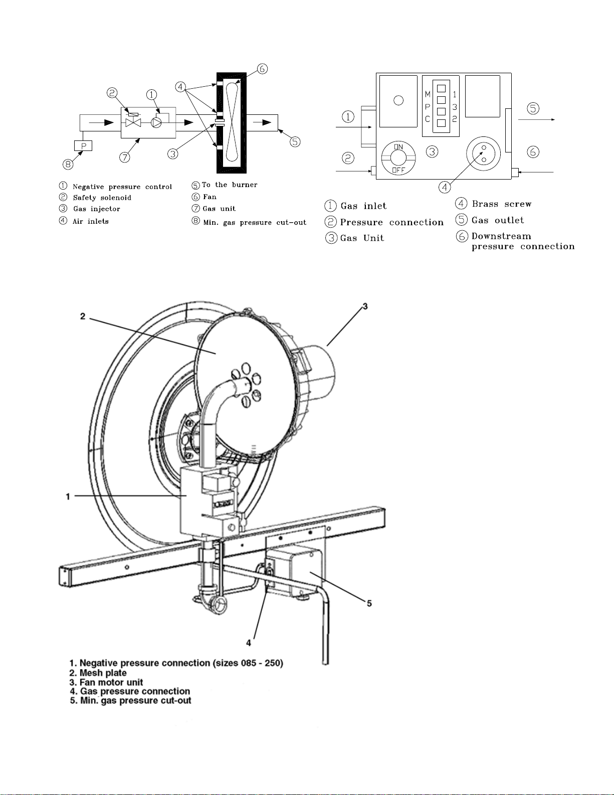
- Check the gas pipe is leak-tight upstream of the gas unit (see
drawing). Use Typol or a foaming product ("1000 bulles" aerosol or
similar). Do not use soapy water.
- Check the pressure upstream of the gas unit (the pressure con-
nection is located on the minimum gas pressure cut-out). This
cut-out must be set to 15 mbar. This operation must be carried
out while the burner is not operating.
- Check voltage at the TNS2 transformer output:
- 115 volts for power supply of the IGN module (L1 - L2 and S1 -
S2).
230 volts for power supply of the burner fan motor.

10
Figure 5 Figure 6
Detail of the Gas Section

11
4. Reconnect the sensor and re-ignite the burner. Once the
burner is ignited, simulate a high temperature failure by dis-
connecting a wire from the sensor TC01. The gas valve
should close and stop the flaem, re-connect TC01. The ig-
nition sequence will be initiated. The burner should re-light
after about 45 seconds.
5. Once the burner is ignited, simulate overheating by discon-
necting a wire from the sensor TC02. This stops all the
burner's elements (fan and gas valve should no longer be
energized). Reconnect the TC02 wire.
Adaption to available gases (See Table 3)
The gas-fired heating modules built into YK* units are avail-
able in different categories. The units are supplied ready to
operate using natural gases G20 (20 mbar) and G25 (25
mbar) or using gas G31 (37 mbar).
The transition from G20 gas to G25 gas does not require any
action. The available power in G25 gas supply is reduced.
The transition from G20 to G31 gas requires the following
modifications.
- Change of the gas intake orifice in the burner's fan.
- Implementation of pressure limiter.
The orifice and the limiter
for supply with gas G31 must be manufactured by
Trane.
.
Start up
Operating check list before the start-up
- Unit is level, with sufficient clearance all around.
- Duct network is correctly dimensioned according to the unit
configuration, insulated and water tight.
- Condensate drainage line is correctly dimensioned, equipped
with trap and sloped.
- Filters are in position: correct size and quantity, clean.
- Wiring is correctly sized, and connected in accordance with
wiring diagrams.
- Power supply lines are protected by recommended fuses
and correctly earthed.
- Thermostat is correctly wired and positioned unit is checked
for refrigerant charge and leaks.
- Indoor and outdoor fans rotate freely and are fixed on shafts.
- Indoor fan rotation speed is set.
- Access panels and doors are replaced to prevent air entering
and risks of injury.
- Checking of the gas heating section, in accordance with
above precedure.
If any operating checks
must be performed with the unit operating, it is the
technician's responsibility to recognize any possible
hazards and proceed in a safe manner. Failure to do
so could result in severe personal injury or death due
to electrical shock or contact with moving parts.
- Measure the negative pressure downstream of the gas unit.
Connect a flexible hose to the gas unit branch connection
and connect as electronic pressure gauge, or failing this a
U tube.
- Start the burner by modifying the thermostat's set point or by
using the "test mode" terninals on the machines terminal
strip.
- Measure the downstream partial vacuum. It must be between
- (minus) 5 mm and - (minus) 9 mm of water head.
- Check the supply pressure upstream of the gas unit once
more when it is operating to ensure the pressure has not
dropped.
Important note: In the event this measurement is
correct, do not adjust the gas unit setting. It has been
set in the factory.
When the measured partial vacuum is positive (above
atmospheric pressure)
- Remove the paint mark on the brass threaded plug with two
holes drilled in it, located on the gas unit, and unscrew it
(See Figure 6).
- To increase the partial vacuum turn the screw counter-clock-
wise.
- Measure the partial vacuum again while the burner is operat-
ing.
- When the adjustment is finished, seal the brass threaded
plug with paint.
It is highly recommended to check the combustion gases with
a flue gas analyzer. The measured valves must be within the
following ranges:
-Carbon monoxide (CO) less than 50 PPM
-Oxygen (O2) greater than 1.5%
-Carbon dioxide (CO2) less than 11%
Note: If the correct setting cannot be obtained,
contact the Trane technicians.
Checking the correct operation of the burner
After having iginited the burner a few times, it is necessary to
check the proper operation of the burner safeties by following
the following procedure:
1. Close the main gas valve, and then simulate a demand for
heating. The burner must start, and then stop when the
quantity of gas contained in the pipe between the main
valve and the built-in gas unit has run out. To ensure this
takes place, following the drop in supply pressure, the
LPGS cut-out must open and stop all the gas supply chain
components (fans, gas valve, ignition controller). Any at-
tempt to ignite the system again must fail.
2. Open the main gas valve. The pressure switch LPGS
should automatically reset. The burner can now be put
back into operation.
3. Ignite the burner. Once it is burning, simulate a flame failure
by disconnecting a wire of the flame detection sensor
(quick connect). The ignition controller should immediately
stop the burner and close the gas valve.

12
Table 3- Units Equipped with Gas Heating Modules, CE Marked
Sales Reference G205 G250 G350 G400
Rooftop Air Conditioner
50 Hz EEC Voyager
G20 41,4 (92%) 49,1 (91%) 70,6 (90%) 77,4 (91%)
G25 35,0 (92%) 38,3 (89%) 59,4 (88%) 60,3 (90%)
G31 37,7 (92%) 48,6 (90%) 57,3 (88%) 78,2 (92%)
YK*063CD X
YK*073CD X
YK*073DD X
YK*085CD X
YK*089CD X
YK*100CD X
YK*100BD X
YK*125CD X
YK*155BD X
YK*175CD X
YK*200BD X
YK*250BD X
Gas Module Heating Capacity kW PCI (Output %)

13
Table 4 - Characteristics of G20, G25 and G31 Gases used by Gas-Fired Heating Modules fitted to
YK* Roof Top Air Conditioners
Module de chauffage G205 G250 G350 G400
Natural Gas G20 (20mbar)
34.02 MJ/m3 (15 C-1013)
Injector diameter (mm) 6,05 7,67 8,20 10,69
Heating Capacity (kW) 77,4 41,4 49,1 70,6
Minimum Gas Pressure (Trip-out) (mbar) 15,0 15,0 15,0 15,0
Normal Rate
Gas Flow (15 C-1013 mbar) (m3/h) 3,1 4,8 5,7 8,3
Heat Rate (kW) 45,0 54,0 78,7 85,0
Reduce Rate
Gas Flow (15 C-1013 mbar) (m3/h) 4,6 5,1 8,1 8,5
Heat Rate (kW) 43,5 48,0 76,8 80,0
Natural Gas G25 (20 ou 25 mbar)
29.30 MJ/m3 (15 C-1013)
Injector diameter (mm) 7,67 8,20 9,80 10,69
Heating Capacity (kW) 35,0 38,3 59,4 60,3
Minimum Gas Pressure (Trip-out) (mbar) 15,0 15,0 15,0 15,0
Normal Rate
Gas Flow (15 C-1013 mbar) (m3/h) 4,7 5,3 8,3 8,2
Heat Rate (kW) 38,0 43,0 67,4 67,0
Reduce Rate
Gas Flow (15 C-1013 mbar) (m3/h) 4,5 4,9 7,8 7,9
Heat Rate (kW) 36,5 40,0 63,4 64,0
Natural Gas G31 (30, 37ou 50 mbar)
88.00 MJ/m3 (15 C-1013)
Injector diameter (mm) 5,40 6,67 7,37 8,50
Heating Capacity (kW) 37,7 48,6 57,3 78,2
Minimum Gas Pressure (Trip-out) (mbar) 20,0 20,0 20,0 20,0
Normal Rate
Gas Flow (15 C-1013 mbar) (m3/h) 1,7 2,2 2,7 3,5
(kg/h 3,2 4,2 5,1 6,6
Heat Rate (kW) 41,0 54,0 65,3 85,0
Reduce Rate
Gas Flow (15 C-1013 mbar) (m3/h) 1,6 2,2 2,6 3,2
(kg/h) 3,0 4,1 4,9 6,1
Heat Rate (kW) 38,5 53,0 62,6 78,0
Combustion Air Flow (m3/h) 60,0 72,0 98,0 113,0
(Avec E=25%)
NOTE: GAS FLOW MAY VARY BY AS MUCH AS ± 10%
MARKING CATEGORY OF THE GAS SECTION IN THE
DIFFERENT COUNTRIES
NL FR BE GB/ES IT DE
Netherlands France Belgium United Kingdom Italy Germany
ll2L3P ll2E +3P l2E + ll2H3P l2H + l 2E
I 3P (Natural Gas Only) I 3P
G20 - 20 mbar
G31 G31 G37
30 mbar 37 mbar 50 mbar

14
Figure 7- Trane Gas Heating Module Ignition Controller Start and Safety Sequence
Normal Sequence Sequence With Safety Measures
(Stop by Regulation) At Ignition with Flame Signal Fault At Disappearance of Flame Signal
Time (s) 3 Retries 186.3 s 3 Retries 186.3 s
Operations
0
54
59.7
60.9
Manuel
Regulation
0
54
59.7
62.1
72min
etc..
0
0,98
2
55
59.7
62.1
72min
etc..
Gas Valve
Fan
Electrode
Heating
Ionisation TSA = 8,1s TSE = 0,96S maxi
Use the following steps to complete the installation of the unit
gas piping. (See Figure 8)
1. Install a tapped, style A(1/8 inch NPT tap) shut-off gas cock
at the end of the gas supply line near the unit. Be sure the
tapped gas cock is downstream of the pressure regulator, if
used.
Note: The shut-off gas cock must be installed
outside the unit, and should meet the specifications
of all applicable National and Local Codes.
2 . Install a ground union joint downstream of the shut-off
cock. This joint must be installed outside of the unit.
3 . Install a drip leg (at least 150 mm (6") in depth) next to the
union as shown in Figure 8. This drip leg is required to col-
lect any sediment that may be deposited in the line.
4 . Before connecting the piping circuit to the unit, bleed the air
from the supply line. Then cap or plug the line and test the
pressure at the tapped shut-off cock. The pressure reading
should not exceed 35 mBar (14 inches water column).
5. Connect the gas piping to the unit. Check the completed
piping for leaks using a soap and water solution, or equiva-
lent.
Figure 8
Gas Piping Schematic
IMPORTANT NOTE: THIS UNIT USES A NEGATIVE
REGULATION GAS VALVE. AT START-UP, THE
OUTLET PRESSURE SHOULD BE CHECKED AND
ADJUSTED IF REQUIRED TO A (NEGATIVE) -50Pa (-
0.2" OF WATER COLUMN.) NEVER ADJUST THE
REGULATOR TO A POSITIVE PRESSURE.
Manifold Pressure
The unit manifold pressure regulator (located on the gas
valve) is factory installed and adjusted to provide the rated unit
heating capacity. The required manifold pressure is factory set
at (negative) - 50 Pa (2 inches of water column) for natural
and LP gas.
Check the manifold pressure at the unit gas valve. Do not ex-
ceed the recommended pressure shown on the unit name-
plate.
Filter Installation
To gain access to filters, remove the evaporator fan access
panel. Each unit ships with 50 mm (2") filters. Number and
size of filters is determined by size and configuration of the
unit. Refer to the unit “Service Facts” for filter requirements.
Evaporator Fan Adjustment
Use the following procedure to determine the proper adjust-
ment of the evaporator fan sheaves for a specific application.
1. Determine total system external static pressure Pa (inches
of water column) with accessories installed. To accomplish
this:
a. Obtain the design airflow rate and the design external
static pressure drop through the distribution system. Your
sales representative or the design engineer can provide
you with these values.
b. Using the table from the Service Facts, add the static
pressure drop of the accessories installed on the unit.
c. Add the total accessory static pressure drop (from step
1b) to the design external static pressure. The sum of
these two values is the total system external static
pressure.
2. Use the table(s) in the Service Facts to find the external
static pressure Pa (inches of water column) that most
closely approximates total system external static pressure.
Then locate the appropriate airflow rate (in m3/h) for your
unit. The value obtained represents the kW for the evapora-
tor fan motor and the fan RPM.

15
Important: kW (BHP) listed in the Table is the
percentage range of nameplate amperage the motors
will safely work within before an oversized motor is
required.
3. Adjust the variable pitch pulley to increase or decrease the
fan RPM as required. See Figure 9.
Figure 9
Typical fan, motor, and sheave assembly
TO INCREASE m3/h (CFM)
Loosen the pulley adjustment set screw and turn sheave
clockwise
TO DECREASE m3/h (CFM)
Loosen the pulley adjustment set screw and turn sheave
counter-clockwise
TO INCREASE BELT TENSION
Loosen the nut (next to the idler sheave) that secures the
sheave in place. With a wrench, apply pressure clockwise on
the outside nut (round headed one), until tension desired is
reached. While holding pressure with the tension nut, retighten
the nut next to the idler sheave.
Electrical Connections
Electrical wiring and grounding must be installed in accor-
dance with national and local codes.
Electrical Power
It is important that proper electrical power is available for the
unit. Voltage variation should remain within the limits stamped
on the nameplate.
Power Entry
Holes are provided for low-voltage and high-voltage wiring. It
is not necessary to punch any new holes in either the interior
or exterior unit panels. If new holes are punched, performance
will be adversely affected unless they are resealed to be both
air- and watertight.
Disconnect Switch
Provide an approved weather-proof disconnect either on the
side of unit or within close proximity.
Over Current Protection
The branch circuit feeding the unit must be protected in accor-
dance with national and local codes.
Power Wiring
The power supply lines must be run in weather-tight conduit to
the disconnect, and into the bottom of the unit control box.
Provide strain relief for all conduit with suitable connectors.
IMPORTANT NOTE: Units with Scroll Compressors
only. Proper scroll compressor rotation is determined
by main power electrical connections. (See
Compressor Electrical Phasing section.)
Provide flexible conduit supports whenever vibration transmis-
sion may cause a noise problem within the building structure.
Insure all connections are made tight.
Note: For branch circuit wiring (main power supply
to unit disconnect), wire size for the length of run
should be determined using the circuit ampacity
found on the unit nameplate.
GROUNDING: THE UNIT MUST BE ELECTRICALLY
GROUNDED IN ACCORDANCE WITH NATIONAL AND LO-
CAL CODES.
Note: Unit must be grounded for igniter to operate
properly. Gas pipe to unit is not an adequate ground.
Ground the unit internally as provided. See unit
wiring diagram for location of grounding lug.
Control Wiring
Note about 24V Volt Transformers:
Units have intergal circuit breakers in their low voltage trans-
formers. If the breaker trips, be sure to open the unit discon-
nect before attempting to reset the breaker.
Open and lock unit
disconnect. Failure to do so could result in severe
personal injury or death due to electrical shock.
Remove compressor access panel and control box panel to
access transformer. Reset by pressing in on the black reset
button located on the left side of the transformer.
Replace all panels before restoring power to the unit.
Note: The unit 24 volt transformer must not be used
to power Field Installed Accessories (FIA), except for
the ones that are factory supported.

16
Figure 10
Typical Field Wiring Diagram
Low voltage control wiring must not be run in conduit with
power wiring. Route low voltage wire from zone sensor termi-
nals through 7/8 inch bushing in the unit. See dimensional
data for control wire entry location. Make connections as
shown by the appropriate low voltage wiring diagrams in Fig-
ure 10.
Zone Temperature Sensor conductors are standard thermostat
wire. The only exceptions are Tracer/Tracker installations
which utilize a serial communications link and require a
shielded twisted pair of conductors between the Tracer/
Tracker and the (TCI) Communications Interface.
Recommended wire sizes and lengths for installing the Zone
Temperature Sensor are provided in Table 5. Ensure that the
wiring between the controls and the unit's termination point
does not exceed two and a half (2.5) ohms/conductor for the
length of the run. Resistance in excess of 2.5 ohms per con-
ductor can cause deviation in the accuracy of the control.
Table 5.
DC Conductors
Wire size (mm2) Maximum wire length (m)
0.33 45
0.50 76
0.75 115
1.30 185
2.00 300
NOTE: Do not run the electrical wires transporting DC
signals in or around conduit housing high voltage
wires.
Zone Temperature Sensor and low voltage terminal
designations are no longer R-W-Y-G-B etc, they are now 1-2-3
etc. Connections should be made using 1 to 1, 2 to 2, 3 to 3,
and so on. See following example.
Zone Temperature Sensor Terminal Strip
Terminal # Terminal I.D.
1ZTEMP
2 SIGNAL COMMON
3CSP
4MODE
5HSP
6 LED COMMON
7 HEAT LED
8 COOL LED
9SYSONLED
10 SERVICE LED
Zone Low
Sensor Voltage
Module Terminal Board
(ZSM) (LTB)
1 [ ] [ ] 1
2 [ ] [ ] 2
3 [ ] [ ] 3
4 [ ] [ ] 4
5 [ ] [ ] 5
Emergency Shut Down
For Emergency Shut Down, remove the jumper between LTB-
16 and LTB-17 and install normally closed contacts (Open at
Fault Condition). Immediate shut down will occur and the UCP
will be disabled.
Compressor Disable
To disable Compressor #1, remove the jumper between LTB-
13 and LTB-14 and install normally closed contacts (open to
disable).
To disable Compressor #2, (if applicable), remove the jumper
between LTB-14 and LTB-15 and install normally closed con-
tacts (open to disable).
Scroll Compressors
(125 - 250 Units only)
Because scroll compressors are uniquely different from tradi-
tional reciprocating compressors, their operating characteris-
tics and requirements represents a departure from reciprocat-
ing compressor technology.
Proper phasing of the electrical power wiring is critical for
proper operation and reliability of the scroll compressor.
Proper rotation of the scroll compressor must be established
before the unit is started. This is accomplished by confirming
that the electrical phase sequence of the power supply is cor-
rect. The motor is internally connected for clockwise rotation
with the inlet power supply phased A, B, C.

17
Figure 11A
Zone Sensor Interconnections

18
Figure 11B
Conventional Thermostat Interconnections

19
Diagram Improper Electrical Phase Sequence
Proper compressor motor electrical phasing can be quickly de-
termined and corrected before starting the unit. Use a quality
instrument such as an Associated Research Model 45 Phase
Sequence Indicator and follow this procedure.
1. Open the electrical disconnect or circuit protection switch
that provides line power to the High Voltage Terminal Block
(HTB1) in the control panel.
2. Connect the phase sequence indicator leads to the HTB1
as follows:
Phase Seq. Lead HTB1 Terminal
Black (Phase A) L1
Red (Phase B) L2
Yellow (Phase C) L3
Bodily injury can result
from high voltage electrical components. If operating
checks must be performed with the unit operating, it
is the technician’s responsibility to recognize these
hazards and proceed safely. Failure to do so could
result in severe personal injury or death due to
electrical shock or contact with moving parts.
3 . Read the phase sequence on the indicator after turning
power on by closing the unit disconnect switch. The “ABC” in-
dicator on the face of the phase indicator will glow if phase is
ABC.
4. If the “CBA” indicator glows instead, open the unit main dis-
connect and interchange any two main line leads on HTB1. re-
close the unit main disconnect and recheck phasing.
5. Open units main disconnect before continuing with installa-
tion.
6. Disconnect the phase indicator.
Open and lock unit
disconnect switch before continuing installation.
Failure to do so could result in severe personal injury
or death due to electrical shock or contact with
moving parts.
Note: If a phase indicator is not available, follow the
electrical phasing sequence in the cooling start-up
section to insure proper compressor rotation.
IMPORTANT: After completion of wiring, check all
electrical connections, including factory wiring within
the unit, and ensure all connections are tight. Replace
and secure all electrical box covers and access doors
before leaving unit or connecting power to circuit
supplying unit.
After all electrical wiring is complete, SET THE ZONE SEN-
SOR SWITCH TO THE OFF POSITION AND THE FAN
SWITCH TO AUTO SO COMPRESSORAND FAN WILL NOT
RUN, and apply power by closing the system main disconnect
switch. This will activate the compressor crankcase heaters.
Do not change the zone sensor setting until power has been
applied long enough to evaporate any liquid refrigerant in the
compressor. It is recommended the crankcase heaters be en-
ergized for 8 hours prior to starting.
Exception - Both circuits on the125 thru 250 units are not
equipped with crankcase heaters.
Start-Up
Pre-Start Quick Check List
[ ] Is unit properly located and level with proper clearances?
See Figure 1A and 1B.
[ ] Is the duct work correctly sized, run, taped, insulated and
weather proofed with proper unit arrangement? (See duct
work installation)
[ ] Is the gas piping correctly sized, run, and purged of air?
(See gas piping)
[ ] Is condensate line properly sized, run, trapped and
pitched?
[ ] Is the filter of the correct size and number, clean and in
place?
[ ] Is the wiring properly sized and run in according to the unit
wiring diagram?
[ ] Are all wiring connections tight including those in unit and
compressor electrical boxes?
[ ] Has the unit been properly grounded and fused with the
recommended fuse size? (see wiring data)
[ ] Is the zone temperature sensor correctly wired and in a
good location?
[ ] Have the air conditioning systems been checked at the
service ports for charge and leak tested if necessary?
[ ] Does the condenser fan and indoor blower turn freely
without rubbing and are they tight on the shafts?
[ ] Has the indoor blower speed been determined and the
proper speed been set? (See air flow performance data)
[ ] Has all work been done in accordance with applicable local
and national codes?
[ ] Are all covers and access panels in place to prevent air
loss and safety hazards?
Bodily injury can result
from high voltage electrical components. If operating
checks must be performed with the unit operating, it
is the technician’s responsibility to recognize these
hazards and proceed safely. Failure to do so could
result in severe personal injury or death due to
electrical shock or contact with moving parts.

20
Power-up Initialization
The “initialization” by the Unitary Control Processor (UCP) oc-
curs each time the system is powered-up. The UCP performs
internal self-diagnostics checks, which include identifying the
equipment components of its system, and the configuring of it-
self to that system. It also checks itself to be sure it is function-
ing correctly. On units with the optional economizer, the
damper is driven open for 15-20 seconds and then fully closed
for 90 seconds. The UCP system indicator LED is turned to
“ON” within one second of start-up if operation is correct.
The Unitary Control Processor (UCP) switches are factory set
to provide comfort for most applications. Control cycles may
be adjusted as indicated in the table below. These switches
function similar to the heat anticipator adjustment in conven-
tional thermostats.
Unitary Control Processor (UCP)
Switch Settings for Cycle Timing
Switch 1 Switch 2 Cycle Time
OFF OFF NORMAL (Factory Setting)
OFF ON LONGER
ON OFF SHORTER
ON ON *SPECIAL
* Special applications, where very short cycles are
necessary to prevent excessive temperature swings.
Starting the Unit in the Heating Mode
Note: See “Sequence of operation” in the unit Service
Facts for a complete description of heating operating
sequence.
Check to ensure all grilles and registers are open and all unit
access doors are closed before start-up.
Purge the gas supply line of air by opening the union ahead of
the unit. When the odor of gas is detected, re-tighten union
and wait 5 minutes before proceeding.
Place the zone system switch in the heat position.
Postition the heating setpoint approximately 6oC (10oF) de-
grees above room temperature and place the fan switch in
"Auto" or "On" position.
Open the main gas valve and turn on unit main power supply.
Note: To bypass time delays, and verify the operation
of this unit from the roof, use the “Test mode
procedure” on page 3 and 4 of this manual.
The combustion blower motor and ignitor should energize.
The main burners should light within one minute from the time
the combustion blower starts. Initial start may be delayed
somewhat if unit is not purged and air is trapped in gas line.
If burners fail to ignite after 3 tries the ignition system will lock-
out. Reset by disconnecting and re-applying unit power.
Unit will start in the high fire mode. After a short run cycle it will
switch to low fire.
Note: Blue smoke produced by the heat exchanger
during the initial burner firing is caused by a thin film
of oil on the surface of the heat exchanger. This oil
will burn off quickly.
Check control operation and burner operating conditions
through the sight glass in burner assembly cover.
Manifold Pressure
Connect a manometer to the pressure tap at the outlet side of
the unit gas valve. Read the manifold pressure with the main
burners firing. The manifold pressure reading indicated should
be a (negative) -50 Pa (2 inches of water column.)
If the manifold pressure reading does not match the value indi-
cated on the unit nameplate, the unit pressure regulator must
be adjusted as follows:
Remove the cover screw on the gas regulator (located on the
top side of the unit gas valve).
Turn the adjusting screw clockwise to increase manifold pres-
sure, or counter-clockwise to decrease manifold pressure.
Open and lock unit
disconnect switch before continuing installation.
Failure to do so could result in severe personal injury
or death due to electrical shock or contact with
moving parts.
Adjust the evaporator fan motor rpm (at the motor sheave) to
a speed which most closely approximates the rpm value found
in the motor sheave/fan speed (rpm) table in the Service
Facts. To insure proper unit operation, the resulting airflow
must be within + or - 20 percent of the nominal airflow rate.
After adjusting the evaporator fan, check heat exchanger tem-
perature rise during furnace operation to insure that it falls
within the range specified on the unit nameplate.
If the temperature rise noted is outside of the specified limits,
adjust the fan motor sheave to cause the temperature rise of
the heat exchanger to fall within the required range.
Heating Shut-down
To exit the test mode, disconnect unit power for 3-5 seconds
and reapply. When running the unit using the zone sensor as
the control, position the selector switch at "Off". There will be a
delay of 0 - 90 seconds before the unit shuts down in this set-
ting.
Do not operate the unit
without the evaporator fan access panel in place.
Reinstall the access panel after performing any
maintenance procedures on the fan. Operating the
unit without the access panel properly installed may
result in severe personal injury or death.
This manual suits for next models
8
Table of contents
Other American Standard Fan manuals
Popular Fan manuals by other brands

ATC
ATC BFA Series Assembly instruction

Bestron
Bestron Summer Breeze ADF30DZ instruction manual

CONCORD
CONCORD Ponderosa 52PD Owner's manual and installation instructions

Xpelair
Xpelair SL100 Installation and maintenance instructions

Harmann
Harmann VIVO.P 2-190/500 S Assembly instruction

Lasko
Lasko 2012 white operating manual