AMF 1970 SKI-DADDLER SD15M21 A Quick start guide

)
PARTS
AND
SERVICE
MANUAL
~970
SKI-DADDLER
SNOWMOBILES
MARK
VI
[SD15M21
A]
MARK
xx
[SDI5M11A]
MARK
xx
[SDI5M22A]
MARK
xx
[SDI5M23A]
AMERICAN
MACHINE
&
FOUNDRY
COMPANY
CONSUMER
PRODUCTS
SA
L
ES
DIVISION
PARTS
&
SERVICE
DEPARTMENT
Whiteford
Road,
York,
Pennsylvania
17402
PART NO
37894
-

o

c
c
~I
TABLE
OF
CONTENTS
INrRODucrloN
PREDELIVERY
INSrRUCTlONS .
Install Ski
Assembly
. . . .
Install Windshield Ass
embly
Fuel Mixture Instructions
Lubrication . . . . . .
SERVICE
AND
REPAIR
Hood Removal
and
Installation
Hood
Assembly
Repair . . . .
Replace Lamp Assemblies . . .
Steering
and
Ski
As
s
embly
Alignment
.
°To
Remove
Drive Chain
Drive Chain
Adjustment
To
Remove
Variable-Speed Drive
Belt.
Variable-Speed Drive Belt
Adju
s
tm
ent
To
Remove
Drive Clutch
Drive Clutch
Alignment.
.
To
Remove
Driven Clutch .
To
Remove
Brake
Assembly
Brake
Adjustment
. 0 • •
To
Remove
Carburetor-Mark
VI
and
Mark
XX
295
only
To
Remove
Carburetor-Mark
XX
399
and
439
only.
Carburetor
Adjustment
. . . . . . . .
Throttle Plate
Adjustment,
HD
Carburetor . . . . .
Throttle Plate
Adjustment,
HR
Carburetor . . . . .
To
Remove Engine
and
Support
Assembly-Mark
VI
only
To
Remove
Engine
and
Support
Assembly-Mark
295
only
CONTENTS
To
Remove
Engine
and
Support
Assembly-Mark
XX
399
and
439
only
To
Remove
Gas
Tank
..
To
Remove
Muffler
To
Remove
Bogie
Wheel
To
Remove
Bogie
Wheel
and
Support
Assembly
To
Remove
Bogie
Wheel
Torsion
Springs.
0
To
Remove
Traction Belt Take-Up
Assembly
To
Remove
Sprocket Seals
and
Be
arings
To
Re
move
Drive Sprocket
Assembly
To
Re
move
Traction Belt
Traction Belt
Adjustment
. .
Spark Plug Interchangeability
Wiring
Diagrams
Troubleshooting.
. • . . .
Iu.usrRArED PARrS
L1sr
.
Pag
e
3
3
3,
3
4
4
5
5
5
5
5
6
6
7
7
7
8
8
8
8
9
9
10
10
10
JJ
JJ
12
12
13
13
13
13
13
14
14
14
15
16
J6
16


c
INTRODUCTION
This
manual
has
been
prepared
to
provide
all
authorized
AMF
Ski-Daddler
Dealers,
Distributors
and
technicians
with
the
instructions
neces
sar
y
to
service
and
maintain
the
following 1970 AMF S
ki-
Daddler
snowmobiles.
Model
Designation
Mark
VI
(SD15M21A)
Mar
k XX (SD15MllA)
Mark
XX (SD15M22A)
Mark
XX
(SD15M23A)
Engine
Hirth
171R 634cc
JLO
L-295R
AMF
399BP
AMF 439BP
This
manual
is
presented
in
two
sections.
The
first
section,
Maintenance,
provides
the
instructions
necessary
for
sled
maintenance
and
service
while
the
second
section,
the
Illustrated
Parts
List
is
provided
to
assist
in
the
identification
of
all
major
assemblies
and
component
parts.
For
engine
maintenance,
refer
to
the
vendor
manual
for
the
particular
engine
or
the
AMF Engine
Main-
tenance
Manual
issued
for
all
AMF
engines.
If
the
information
in
this
manual
is
not
applicable
to
all
models,
the
exceptions
will
be
noted and
the
correct
information
for
the
particular
model
will
be
given.
PREDELIVERY INSTRUCTIONS
The
1970
Ski-Daddlers
are
shipped
completely
as-
sembled
except
for
the
windshield
assembly
and
the
ski
assembly.
These
assemblies,
plus
the
attaching
hardware
will
be found
in
the
shipping
carton.
Carefully
open
the
carton
and
immediately
inspect
the
equipment
for
any
damage
or
missing
items.
Install Ski
Assembly
•
Remove
the
locknut
and
screw
at
the
spring
mounting
bracket
(figure
1).
•
Place
th
e
spindle
pad
in
the
spring
mounting
bracket
with
the
thicker
section
and
the
directional
arrow
on
the
pad
pointing
forward.
NOTE:
The
plastic
bag
containing
the
spindle
pad
will
be
found
in
the
storage
compartment.
•
Install
the
ski
assembly
by
securing
the
spring
mounting
bracket
and
spindle
pad
to
lower
end of
3
~I
INTRODUCTION
IMS1dij
spindle
tube
assembly
as
shown
in
figure
1. Apply
30
foot-pounds
torque
to
the
locknut.
Do
not
over-
tighten
bo
lt
as
t
he
ski
assembly
should
float
freely
on
the
spindle.
•
Repeat
Install
Ski
Assembly
procedures
for
opposite
ski.
Figure 1
NOTE:
Properly
installed
skis
should
toe
out0-
to
1/2-inch
at
the
front
end
(see
figure
2)
and
should
be
symmetrical
about
the
centerline
of
the
sled.
If
alignment
is
necessary,
refer
to
the
Steering
and
Ski
Alignment
procedures.
Install
Windshield
Assembly
•
Remove
the
screws
securing
the
left-
and
right-
hand mounting
strips
to
the
hood.
Remove
the
mounting
strips.
•
Remove
the
protec
t
ive
cover
from
the
wind-
shield.
Place
the
windshield
in
position
on
the
hood
assembly.
Replace
the
mounting
strips
as
shown
in
figure
2.
•
Using
the
original
screws,
loosely
secure
the
mounting
strips
and
windshield
to
the
hood
assembly
starting
at
t
he
center
and
working
to
the
sides.
•
Engage
the
en
ds of
the
mounting
strips
in
the
trim
strip
on
the
windshield
and then
tighten
the
screws,
again
sta
r
ting
at
the
cen
t
er
and
workingto
the
sides.
NOTE:
Check
mounting
strips
for
sharp
edges
or
corners.
Use
a fine tooth
file
to
smooth
all
edges
and
corners.

PREDEL/VERY
/NSTRUCT/O
HOUNTING
STRIP,
RH
HOUNTING
STRIP,
LH
\WI:D
_
~:IELD
TRIH
~
•
TOE
OUT
0-
TO
1/2-
INCH
MAXIHUM
Figure 2
Fuel
Mixture
Instructions
I
WARNING
I
Never
fill
the
gasoline
tank
while
the
engine
is
hot. Wipe off
any
spilled
gasoline
before
attempting
to
start
engine.
The
correct
oil-to-gasoline
ratio
is
20: 1 (20
parts
regular
gasoline
to
1
part
oil). Too
much
oil
will
cause
carbon
deposits.
Too
little
oil
or
a
poor
mix
will
cause
insufficient
lubrication
and
possible
engine
damage.
IMPORTANT:
Gasoline
and
oil
should
be
mixed
at
temperatures
above
zero.
At
temperatures
below
zero,
gas
and
oil
mix
with
difficulty.
4
Fuels
containing
additives
are
not
recommend
ed
for
use
in
Ski-Daddler
engines.
For
mixingwithgaso
-
line,
use
only
oil
that
is
recommended
for
use
in
air-cooled,
2-cycle
engines
such
as
an
AMF
oil
or
an
equivalent
good
grade
of SAE 30
or
40
non-
detergent
motor
oil.
IMPORTANT: Some
outboard
motor
oils
contain
a
detergent
that
works
well
in
outboard
motors
that
operate
at
much
lower
temperatures
because
they
are
water
cooled.
However,
the
detergents
may
cause
spark-plug
fouling
in
the
air-cooled
engines
used
on
your
Ski-Daddler
.
Use
a
mixture
of
gasoline
and
oil
as
shown
in
Fuel
Mixture
Chart,
figure
3.
Never
use
gasoline
left
over
from
the
summer
or
previous
winter.
Mix
the
gasoline
and
oil
thoroughly
in
a
clean
con-
tainer
kept
for
this
purpose
only.
The
best
way
to
ensure
a good
mix
is
to
pour
the
oil
into
the
empty
container
and then add a
small
amount
of
gasoline
and
mix
thoroughly.
Then
add
additional
amounts
of
gasoline
as
shown on
the
Fuel
Mixture
Chart.
Fill
Ski-Daddler
gas
tank
from
this
separate
container
of
mixed
fuel.
Use
a funnel with a
fine-screen
strainer
when
filling
the
tank.
The
gas
cap
is
located
under
the
gas
lid
and
hinge
assembly.
GASOLINE-OIL RATIO
2
0
I
1-1/2
L V
./
/
P
I
N
1/2
T
S
/ /
/
",.-
2 3 4 5
GASOLINE.
GALLONS
FUEl MIXTURE CHART
Figure 3
Lubrication
Refer
to
the
lubrication
chart
for
location
of
grease
fittings,
type of
lubricant
and
frequency.
)

SERVICE
AND
REPAIR
PART
LOCATION
TYPE
OF
LUBRICATION
FREQUENCY
Steering
spindles
Grease
zerk
on
spindle
Low-temperature
grease
20
hours
housings
Drive
chain
Chain
case
housing
No.2
Lithium
bearing
grease
20
hours
Bogie
wheels
Grease
zerk
in
center
of
Low-temperature
grease
20
hour
s
bogie wheel
Sprocket
bearings
Rear
sprockets
No.2
Lithium
bearing
grease
40
hours
LUBRICATION CHART
SERVICE
AND
REPAIR
Hood
Removal
and Installation
• To
remove
the
hood and
headlight
assembly,
disconnect
the
hood
and
the
sled
wiring
harness
at
the
quick-disconnect
below
the
console
on
the
right-hand
side
of
the
sled.
Release
the
hood
latch
assemblies
and
then
remove
the
hood and
headlight
assembly
by
lifting
rear
section
first.
• To
install
the
hood
and
headlight
assembly,
place
the
hood
in
position
on
the
sled
so
that
the
forward
hood
clip
and
the
bottom
edge of
the
hood
engages
the
clips
along
the
inside
edge of
the
bumper
strip.
•
Engage
the
left-
and
right-hand
latch
assemblies
to
secure
the
hood to
the
main
frame.
•
Connect
the
sled
wiring
harness
to
the
hood
wiring
harness
at
the
qUiCk
-disconnect
below
the
console
on
the
right-hand
side
of
the
sled.
Hood
Assembly
Repair
AMF
Fiberglass
Repair
Kits·
are
available
through
your
authorized
AMF
Distributor.
For
large
re-
pairs,
order
AMF
Fiberglass
Repair
Kit No.
1510693.
Smaller
repairs
can
be
made
with
Repair
Kit No. 1510765.
Paint
all
repaired
areas
on
the
hood
using
AMF
-Orange
color
paint
available
in
easy-to-use
spray
container,
AMF
Part
No.
1510828. Follow
the
instructions
in
the
kit
when
making
repairs.
Replace Lamp
Assemblies
Headlight. To
replace
the
headlightlamp
assembly,
simply
raise
the
headlight
assembly,
remove
the
screws
securing
the
cover
assembly
and
remove
5
the
cover
assembly.
Remove
the
defective
head-
light
and
replace
with new
lamp
assembly.
See
illustrated
parts
list
section
for
correct
part
numbers.
Taillight.
Remove
taillight
lens
and
cover
to
ex-
pose
the
taillight
bulbs.
Remove
the
defective
bulb
and
replace
with a new bulb. See
illustrated
parts
list
section
for
correct
part
numbers.
Steering and Ski
Assembly
Alignment
Good
steering
ability
requi
res
that
the
skis
be
properly
set
and
aligned
with
the
sled
body when
the
steering
handle
is
placed
in
the
straight
-ahead
position.
To
determine
that
the
skis
are
properly
aligned,
measure
the
distance
between
the
inside
edges
of
the
skis
at
the
front
end and
at
the
rear.
Properly
aligned
skis
should
toe
out
0-
to
1/2-inch
maximum
at
the
front.
Therefore,
the
overall
measurement
at
the
front
end of
the
skis
should
be
1/2
inch
greater
than
at
the
rear.
If
the
skis
or
steering
mechanism
are
not
properly
set,
adjust
as
follows.
•
Place
steering
handle
in
a
straight-ahead
posi
-
tion.
•
Remove
the
hood
assembly
.
•
Remove
the
bolt
(1,
figure
4), two
spacers
(2),
bottom
spacer
and
locknut
securing
the
rod
end
bearing
(3)
to
the
spindle
arm.
•
Loosen
the
jam
nuts
(4)
securing
both
rod
end
bearings
(3)
to
the
tie
rod
(5).
NOTE:
If
both
skis
need
adjustment,
repeat
pro-
cedure
for
the
opposite
ski.

~eMlal
SERVICE
AND
REPAIR
I~
NOTE: DUring
reasembly,
apply
proper
torque
to
the
clutch
bolt
as
shown
in
figur
e 6.
•
Reassembly
is
the
reverse
of
removal.
Perform
variable-speed
drive
belt
adjustment
and
drive
clutch
alignment
procedures.
Drive Clutch Alignment
•
Remove
the
hood
and
headlight
assembly.
Refer
to
Hood
Removal
and
Installation.
Always
disconnect
spark
plug
wires
before
working
on
the
engine
or
drive
elements.
•
Remove
the
clutch
guard.
•
Loos
en
the
engine holddown
nuts
securing
the
engine
supports
to
the
engine mount
straps
as
illustrated
in
figure
6.
•
Place
a
straightedge
on
the
fixed
face
of
the
drive
clutch
and
move
the
engine
until
the
offset
between
the
straightedge
and
the
front
and
rear
edges
of
the
driven
clutch
is
as
shown
in
figure
6.
Rotate
driven
clutch
90-
degrees
and
repeat
pro-
cedure.
•
Tighten
engine holddown
nuts
and
recheck
align-
ment.
Apply
25
foot-pounds
torque
when
tightening
the
engine
holddown
nuts.
DrMENS
~
ION
MARK
VI
295
R
399
439
A
INCHES
0.30
0.240
0.30
0.30
l
l--fA)
B
INCHES
12-
1/2
I
'"'"
C
FT
-LB
TORQUE
70
~.
:::
S
TR
Ar
GH
T
EDGE
.
~:
DRIVEN
CLUTCH
Figure 6
To
Remove
Driven Clutch
10-
3/4
11
-
1/2
11
-1/2
45 45
70
HOLDDOWN
NUTS
VIEWe
NOTE:
The
procedures
required
to
remove
the
driven
clutch
are
the
same
as
those
described
in
paragraph
To
Remove
Variable
-S
peed
Drive
Belt.
8
To
Remove
Brake
Assembly
•
Remove
hood and
headlight
assembly.
Refer
to
Hood
Removal
and
Installation.
Always
disconnect
the
sparkplugwires
before
working
on
the
engine
or
drive
elements.
•
Disconnect
brake
cable
(8,
figure
7)
at
brake
mounting
bracket
(9)
and
at
brake
actuating
lever
(3).
•
Remove
the
two
bolts
and
locknuts
securing
the
mounting
bracket
to
the
driven
clutch
mounting.
•
Remove
the
brake
assembly.
•
Installation
procedures
are
the
reverse
of
re-
moval.
Refer
to
Brake
Adjustment
procedures.
Figure 7
Brake
Adjustment
~
Always
disconnect
spark
plug
wires
before
working
on
the
engine
or
drive
elements.
• To
adjust
the
brake
pads
(5,
figure
7)
to
the
disk
(1),
remove
the
cotter
pin
(2)
and
tighten
or
loosen
the
castle
nut
(4)
as
required
to
permit
the
brake
pads
(5)
to
just
clear
the
brake
disk.
Reinstall
the
cotter
pin. To
adjust
for
excessive
play
in
brake
cable
or
lever
pOSition,
loosen
jam
nuts
(6)
and
move
brake
housing
(7)
as
required.
Tighten
jam
nuts.

c
c
To
Remove Carburetor-
Mark.
VI
and
Mark.
XX
295 only
(ESj
Always
disconnect
spark
plug
wires
before
working on
the
engine
or
drive
elements.
• Loosen the
throttle
control cable
adjustment
screw
and
release
cable.
On
Mark
VI
only,
re-
lease
throttle
control linkage
at
the
carburetor.
•
Release
the
throttle
extension
spring
and hook
at
the
carburetor
throttle
control
lever
on the
Mark
XX
295 only (s
ee
figure
8).
•
Release
the hose
clamp
and
disconnect
the
im-
pulse
line
at
the
carburetor.
Wipe up any
spilled
gasoline
immediately.
• Rel
ease
the tank
-to-car
buretor
gas
line.
Wipe
up any
spilled
gasoline
immediately.
• Remove the locknuts
securing
the
carburetor
to the
carburetor
adapter
and remove the
car-
buretor.
NOTE:
Do
not
damage
gaskets
when
removing
carburetor.
• In
stal
lation
is
the
reverse
of removal. Adjust
carburetor
as
described
in
Carburetor
Adjustment
procedures.
figure
8
9
ERVICE
AND
REPAIR
To
Remove Carburetor-
Mark.
XX
399 and 439 only
~
Always
disconnect
spark
plug
wires
bef
ore
working on the engine
or
drive
elements.
•
Release
the hose
clamps
and
disconnect
the
tank-to-carburetor
gas
line
(figure
9)
at
the
car-
buretor.
Wipe up any
spilled
gasoline
immediately.
• Remove
th
e locknut
securing
the
throttle
arm
screw
to the
throttle
arm.
figure
9
IMPORTANT:
Before
loosening
th
e
jam
nuts, note
the
space
betweenthebottom
jam
nutandthe
throttle
control
l
ever
.
This
space
must
be
maintained
during
reassembly.
• Loosen the
jam
nuts between the
throttle
arm
and
the
throttle
control
lever
and
remove
th
e
throttle
rod
screw.
• Remove the
jam
nut and
lockwashers
securing
the
car
buretor
to
the intake manifold and
remove
the
carburetor.
•
Installation
is
the
reverse
of
removal
except
that
the
throttle
rod
screw
must
be
insert
edthrough
the
throttle
control
lever
and into the
throttle
arm

SERVICE
AND
REPAIR
I~
sufficiently to
take
up the
play
in
the
throttle
control
lever.
• Adjust
carburetor
as
described
in
carburetor
adjustment
procedures.
Carburetor Adjustment
When adjusting the
carburetor,
best
results
will
be
obtained
if
the
adjustments
are
made on a
warm
engine. During
carburetor
adjustments,
DO
NOT
FORCE ADJUSTMENT SCREWS INTO SEATS.
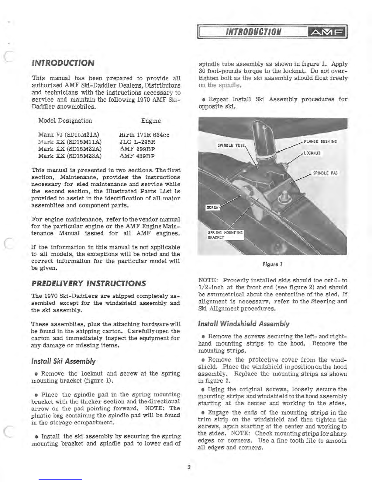
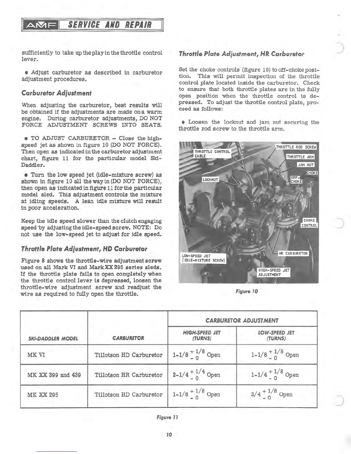
• TO ADJUST CARBURETOR -Close the high-
speed
jet
as
shown
in
figure
10
(DO
NOT
FORCE).
Then open
as
indicated
in
the
carburetor
adjustment
chart,
figure
11
for
the
particular
model
Ski-
Daddler.
•
Turn
the
low
speed
jet
(idle-mixture
screw)
as
shown
in
figure
10
all
theway
in
(DO
NOT FORCE),
then open
as
indicated
in
figure
11
for
the
particular
model
sled.
This
adjustment
controls
the
mixture
at
idling
speeds.
A
lean
idle
mixture
will
result
in
poor
acceleration.
Keep the
idle
speed
slower
than the clutchengaging
speed
'by adjustingthe
idle-speed
screw.
NOTE:
Do
not
use
the
low-speed
jet
to
adjust
for
idle
speed.
Throttle Plate Adjustment,
HD
Carburetor
Figure
8 shows the
throttle-wire
adjustment
screw
used
on
all
Mark
VI
and
Mark
XX
295
series
sleds.
If
the
throttle
plate
fails
to open completely when
the
throttle
control
lever
is
depressed,
loosen
the
throttle-wire
adjustment
screw
and
readjust
the
wire
as
required
to fully open the
throttle.
SKI-DADDLER
MODEL
CARBURETOR
MKVI
Tillotson
HD
Carburetor
MK
XX
399 and
439
Tillotson
HR
Carburetor
MK
XX
295
Tillotson
HD
Carburetor
Throttle Plate Adjustment,
HR
Carburetor
Set the choke
controls
(figure
10)
tooff-choke
posi-
tion.
This
will
permit
inspection
of the
throttle
control
plate
located
inside
the
carburetor.
Check
to
ensure
that
both
throttle
plates
are
in
the
fully
open position when the
throttle
control
is
de-
pressed.
To
adjust
the
throttle
control
plate,
pro-
ceed
as
follows:
• Loosen the locknut and
jam
nut
securing
the
throttle
rod
screw
to the
throttle
arm.
Figure
JO
CARBURETOR
ADJUSTMENT
HIGH-SPEED
JET
LOW-SPEED
JET
(TURNS)
(TURNS)
1-1/8
:
~/8
Open
1-1/8
+
1/8
Open
- 0
2-1/4
+
1/4
Open
- 0
1-1/4
+
1/8
Open
- 0
1-1/8
+
1/8
Open
- 0
3/4
:
~/8
Open
Figure JJ
JO
)

•
Turn
the
throttle
rod
screw
as
required
to
adjust
the
throttle
control
plate
to the fully open
position
when the
throttle
control
is
depressed.
• Tighten the locknut and
jam
nut
at
the
throttle
arm
(figure 10) to
secure
the
throttle
rod
screw.
To
Remove
Engine
and
Support
Assembly-
Mark
VI
only
• Remove the hood and headlight
assembly.
Refer
to Hood Removal and
Installatio
n.
Always
disconnect
the
sparkplugwires
before
working on the engine
or
drive
elements.
• Remove
the
drive
clutch.
Refer
to
paragraph
To Remove
Drive
Clutch.
NOTE:
Figure
5,
Illustrated
Parts
List
section
of
this
manual contains a
detailed
explodedviewofthe
engine and
support
assembly
showing
all
attaching
hardware.
For
engine
maintenance
instructions,
refer
to the engine manual.
• Loosen the flexible tube
clamps
securing
the
muffler
exhaust
tubes
to the engine exhaustmanifold
and
release
the
exhaust
tubes.
•
Disconnect
the
throttle
control
cableand
remove
the
carburetor
as
described
in
paragraph
To
Re-
move
Carburetor.
• Disconnect the
wire
leads
at
the engine.
• Remove the bolts and
washers
securing
the
engine mounting
frame
to the main
frame.
• Lift
the
engine until the engine mounting
frame
clears
the shock mounts and
remove
the engine
tow
ard
the
rear
of the
sled.
• Remove the
bolts
and
washers
securing
the
mounting
frame
to
the engine
base
and
remove
the
mounting
frame.
NOTE: During
reassembly,
the
mounting
frame
ml.lst
be
secured
to the engine
base
before
reinstalling
the engine.
•
Installation
procedures
are
the
reverse
of
removal.
JJ
~I
SERVICE
AND
REPAIR
le2la~
To
Remove
Engine
and
Support
Assembly-
Mark 295
only
• Remove the hood and headlight
assembly.
Refer
to Hood Removal and
Installation.
Always
disconnect
the
spark
plu
g
wire
before
working on the engine
or
drive
elements.
• Remove the
drive
clutch.
Refer
to
paragr
aph
To Remove
Drive
Clutch.
NOTE:
Figure
6,
Illustrated
Parts
List
section
of
this
manual contains a
detailed
explodedviewofthe
engine and
suppor
t
assemb
ly
showing
all
attaching
hardware.
For
engine maintenance
in
s
truction
s,
refer
to
the engine manual.
• Loosen the flexible tube
clamp
securing
the
muffler
exhau
st
tube to the engine exhaustmanifold
and
release
the exhaust tube.
• Disconnect the
throttle
control
cable
anqremove
th
e
carburetor
as
described
in
paragraph
To
Re-
move
Carburetor.
• Disconnect the
wire
lead
at
the engine.
• Remove the locknuts and
washer
s
securing
the
engine and engine mounting
strap
s to the
main
frame.
During
reassembly,
tighten
th
e locknuts
sufficiently to allow a
5/16-inch
clearance
as
shown
in
figure
12.
• Lift the engine until the mounting
straps
clear
the
carriage
bolt
s and
shock
mounts. Remove
the
unit
toward
the
rear
of the
sled.
NOTE:
Do
not
remove
the
carriage
bolt
s,
shock mounts
or
bushings unle
ss
necessary
for
replacemen
t.
5
16
Figure
J2

§
SERVICE
AND
REPAIR
'IRING DIAGRAM
lARK
XX
399CC
(SD
J
5M22A)
'ARK
XX
439CC
(SD
J
5M23A)
IGNITION SWITCH
OFF
ON
RED
TACHOMETER
BLACK
GREEN
NOT
USED
TAIL
LAMP
G:J«
BLACK)
'1fLUE
..
~-+--~~
~.
~~~~
BLUE
YELLOW
WHITE
RED
WHITE
Figure
20
J8
BLACK
BLACK
-=
GROUND
TO
ENG
INE
QUICK
DISCONNECT
AMF
399
AND
439
ENGINE
----:G~
WHITE
WHITE
I
I
I
I
I
!

c
c
c
•
Turn
the
throttle
rod
screw
as
required
to
adjust
the
throttle
control
plate
to
the
fully open
position
when
the
throttle
control
is
depressed.
•
Tighten
the
locknut
and
jam
nut
at
the
throttle
arm
(figure
10) to
secure
the
throttle
rod
screw.
To
Remove
Engine
and
Support
Assembly-
Mark
VI
only
•
Remove
the
hood
and
headlight
assembly.
Refer
to
Hood
Removal
and
Installation.
Always
disconnect
the
sparkplugwires
before
working
on
the
engine
or
drive
elements.
•
Remove
the
drive
clutch.
Refer
to
paragraph
To
Remove
Drive
Clutch.
NOTE:
Figure
5,
Illu
st
rated
Parts
List
sec
tion
of
this
manual
contains
a
detailed
explodedviewof
the
engine and
support
assembly
shOwing
all
attaching
hardware.
For
engine
maintenance
instructions,
refer
to
the
engine
manual.
•
Loosen
the
flexible
tube
clamps
securing
the
muffler
exhaust
tubes
to
the
engine
exhaust
manifold
and
release
the
exhaust
tubes.
•
Disconnect
the
throttle
control
cable
and
remove
the
carburetor
as
described
in
paragraph
To
Re-
move
Carburetor.
•
Disconnect
the
wire
leads
at
the
engine.
•
Remove
the
bolts
and
washers
securing
the
engine mounting
frame
to
the
main
frame.
•
Lift
the
engine
until
the
engine mounting
frame
clears
the
shock
mounts
and
remove
the
engine
toward
the
rear
of
the
sled.
•
Remove
the
bolts
and
washers
securing
the
mounting
frame
to
the
engine
base
and
remove
the
mounting
frame.
NOTE:
During
reassembly,
the
mounting
frame
mqst
be
secured
to
the
engine
base
before
reinstalling
the
engine.
•
Installation
procedures
are
the
reverse
of
removal.
JJ
VICE
AND
REPAIR
To
Remove
Eng
ine
and
Support
Assembly
-
Mark
295
only
•
Remove
the
hood and
headlight
assembly.
Refer
to Hood
Removal
and
Installation.
Always
disconnect
the
sp
ark
plug
wire
before
working
on
the
engine
or
drive
elements.
•
Remove
the
drive
clutch.
Refer
to
paragraph
To
Remove
Drive
Clutch.
NOTE:
Figure
6,
Illustrated
Parts
List
section
of
this
manual
contains
a
detailed
exploded
view
of
the
engine and
support
assem
bly
shOwing
all
attaching
hardware.
For
engine
maintenance
instructions,
refer
to
the
engine
manual.
•
Loosen
the
flexible
tube
clamp
securing
the
muffler
exhaust
tube
to
the
engine
exhaust
manifold
and
release
the
exhaust
tube.
•
Disconnect
the
throttle
control
cable
anqremove
the
carburetor
as
described
in
paragraph
To
Re-
move
Carburetor.
•
Disconnect
the
wire
lead
at
the
engine.
•
Remove
the
locknuts
and
washers
securing
the
engine and engine mounting
straps
to
the
main
frame.
During
reassembly,
tighten
the
locknut
s
sufficiently
to
allow
a
5/16-inch
clearance
as
shown
in
figure
12.
•
Lift
the
engine until
the
mounting
straps
clear
the
carriage
bolts
and
shock
mounts
.
Remove
th
e
unit
toward
the
rear
of
the
sled.
NOTE: Do
not
remove
the
carriage
bolts,
shock
mounts
or
bushings
unless
necessary
for
replacement.
5
16
HOUNTING
STRAP
SHOCK
HOUNT
Figure
J2

-
~t4
JL
.M131
SERVICE
AND
REPAIR
I~
•
Remove
the
bolts
and
washers
securing
the
engine
base
and mounting
straps
to
the
engine.
NOTE:
During
reassembly,
the
mounting
strap
and
engine
base
must
be
secured
to
the
engine
before
installing
the
engine on
the
sled.
Apply
Loc-
Tite
to
the
bolt
threads.
•
Installation
procedures
are
the
reverse
of
re-
moval.
To
Remove Engine
and
Support
Assembly-
Mark
XX
399
and
439
only
•
Remove
the
hood and
headlight
assembly.
Refer
to
Hood
Removal
and
Installation.
Always
disconnect
the
sparkplugwires
before
working
on
the
engine
or
drive
elements.
•
Remove
the
drive
clutch.
Refer
to
paragraph
To
Remove
Drive
Clutch.
NOTE:
Figure
7,
Illustrated
Parts
List
section
of
this
manual
contains
a
detailed
explodedviewof
the
engine
and
support
assembly
showing
all
attaching
hardware.
For
engine
maintenance
instructions,
refer
to
the
engine
manual.
•
Release
the
springs
securing
the
muffler
exhaust
tubes
to
the
engine
exhaust
manifold
and
release
the
exhaust
tubes.
•
Disconnect
the
throttle
control
cable
at
the
throttle
actuator
and
remove
the
carburetors
as
described
in
paragraph
To
Remove
Carburetor.
•
Remove
the
bolts
securing
the
muffler
bracket
to
the
engine. Remove
locknut
that
secures
the
heat
shield
and engine mounting
strap
to
the
main
frame
and
remove
the
heat
shield
and
muffler.
•
Disconnect
the
engine
wiring
harness
at
the
engine.
•
Remove
the
locknuts,
spacers
and
washers
se-
curing
the
engine mounting
straps
to
the
main
frame.
Remove
the
engine, engine
base
and mounting
straps
as
a unit.
During
reassembly,
tighten
the
locknuts
sufficiently
to
allow
a
5/16-inch
clearance
as
shown
in
figure
12.
NOTE:
Do
not
remove
the
carriage
bolts,
shock
mounts
or
bushings
unless
necessary
for
replace-
ment.
J2
•
Remove
the
bolts
and
washers
securing
the
engine
base
and mounting
straps
to
the
engine.
During
reassembly,
apply
Loc-Tite
to
the
bolt
threads.
•
Installation
is
the
reverse
of
removal.
NOTE:
When
replacing
the
engine,
remove
the
starter
cover
plate
from
the
new
engine
to
permit
installa
-
tion
of
the
muffler
bracket.
To
'Remove
Gas
Tank
•
Remove
the
hood and
headlight
assembly.
Refer
to
Hood
Removal
and
Installation.
Always
disconnect
spark
plug
wires
before
working
on
the
engine
or
drive
elements.
•
Check
gas
cap
and
indicator
assembly
to
be
cer-
tain
tank
is
empty,
or
nearly
empty.
•
Remove
the
gas
cap
and
indicator
assembly
(1,
figure
13).
•
Remove
the
bolts
(3)
and
washers
securing
the
gas
spill
chute
(2)
to
the
main
frame
and
remove
the
gas-spill
chute.
•
Disconnect
the
tank-to-carburetor
gas
line
(6)
at
the
gas
tankoutletfitting
(5). Wipe up
any
spilled
gasoline
immediately.
Figure J3
)
)

C •
Remove
the
gas
tank
(4)
by
carefully
sliding
the
tank
up and away
from
the
main
frame.
IMPOR-
TANT: Do
not
damage
the
gas
tank
outlet
(5)
when
removing
the
tank.
c
c
Do
not
attempt
to
make
any
repairs
to
the
gas
tank.
Use
extreme
care
when
removing
the
gas
tank. Do
not
remove
tank
near
flame
or
open
fire.
•
Gas
tank
installation
procedures
are
the
reverse
of
removal.
NOTE:
If
the
original
tank
is
not
to
be
installed,
it
will
be
necessary
to
remove
the
gas
tank
outlet
(5)
and
the
attached
gas
line
filter;
also
the
pressure
relief
valve
(7).
These
items
are
to
be
installed
on
the
replacement
tank.
To
Remove Muffler
•
Remove
the
hood
and
headlight
assembly.
Refer
to
Hood RemOVal and
Installation.
Always
disconnect
the
sparkplugwires
before
working
on
the
engine
or
drive
elements.
•
Loosen
the
flexible
tube
clamp
securing
the
flexible
exhaust
tube(s) to
the
muffler
and
release
the
tube. NOTE: On
Mark
XX 399
and
439 only,
release
the
springs
securing
the
muffler
tubes
to
the
engine
exhaust
manifold.
•
Loosen
the
bolt
and
nut
securing
the
muffler
to
the
mounting
band
assembly.
Remove
the
muffler.
•
Installation
procedures
are
the
reverse
of
removal.
To
Remove
Bogie
Wheel
~
Always
disconnect
the
sparkplugwires
before
working
on
the
engine
or
drive
elements.
•
Remove
the
locknut
(3,
figure
14)
securing
the
bogie
wheel
assembly
(2)
to
the
axle
shaft
and
re-
move
the
wheel.
•
During
reassembly,
torque
the
locknut
(3)
to
28
foot-
pounds.
Be
certain
the
wheel
assembly
(2)
is
installed
with
grease
fittings
on
the
outside.
J3
SERVICE
AND
REPAIR
figure
J4
To
Remove
Bogie
Wheel
and
Support
Assembly
Always
disconnect
the
sparkplugwires
before
working
on
the
engine
or
drive
elements.
•
Remove
the
screws
(1,
figure
14) and
lock-
washers
securing
the
bogie wheel
support
shaft
to
the
main
frame.
•
Remove
the
bogie
wheel
and
support
assembly.
•
Reassembly
is
the
reverse
of
removal.
To
Remove
Bogie
Wheel
Torsion Springs
•
Remove
the
bogies
as
described
in
paragraph
To
Remove
Bogie Wheel and
Support
Assembly.
•
Remove
the
support
shaft
and
separate
the
bogie
wheel
support
halves.
•
Remove
the
torsion
springs.
NOTE: The
torsion
springs
are
iq.entified
as
right-
and
left-hand
springs.
Note
the
direction
of
the
coils
and
the
position
ofthe
springs
to
facilitate
re-
assembly.
•
Reassembly
is
the
reverse
of
removal.
To
Remove Traction Belt Take-Up
Assembly
•
Remove
the
rear
bogies.
Refer
to
paragraph
To
Remove
Bogie Wheel and
Support
Assembly.

~eMlal
SERVICE
AND
REPAIR
I~
•
Release
track
tension
by
loosening
the
right-
and
left-hand
adjusting
nuts
(6,
figure
14)
and
the
adjusting
bolts
(5).
•
Release
the
support
arm
torsion
springs
con-
nected
to th
e
main
frame.
•
Remove
the
right-
and
left-hand
adjusting
angle
locknuts
(6),
washers
and
carriage
bolts
securing
the
traction
belt
take-up
assembly
to
the
main
frame.
•
Remove
the
traction
belt
take-up
assembly
as
a
unit.
NOTE:
The
traction
belt
take-up
assembly
consists
of
the
rear
sprocket
assembly,
spacer
and
asso-
ciated
hardware
held
together
by
the
rear
support
arm
assemblies.
If
necessary
to
remove
seals
or
sprockets,
proceed
as
follows.
•
Carefully
pry
the
oil
seal
away
from
the
rear
support
arm
assembly
(8)
and
remove
the
support
arm
and
adjusting
angle
(9)
clear
of
the
sprocket
shaft
and
bearing.
•
Remove
the
press-on
bearings
and
grease
seals.
•
Remove
the
screws
(10) and
nuts
securing
the
sprocket
plate
and
the
sprocket
to
the
drive
shaft.
Remove
the
plate
and
sprocket.
•
Reassembly
is
the
reverse
of
removal.
During
reassembly
follow
instructions
outlined
in
para
-
graphs
Track
Alignment
and
Track
Tension
Adjust-
ment.
To
Remove
Sprocket Seals
and
Bearings
•
Sprocket
seals
and
bearings
are
located
on
each
end of
the
traction
belt
take-up
assembly
and
the
drive
sprocket
assembly
drive
shafts.
To
replace
the
seals
or
bearings
it
will
be
necessary
to
remove
the
traction
belt
take
-up
assembly
or
the
drive
sprocket
assembly
as
described
in
the
applicable
paragraph.
To
Remove
Drive Sprocket
Assembly
• Remove the hood assembly and set the machine
on
its
right-hand
side.
cr=B
Always
disconnect
spark
plug
wires
before
working
on
the
engine
or
drive
elements.
14
•
Release
the
chain
cover
straps
and
remove
the
chain
cover
top.
•
Remove
the
lower
sprocket
from
the
drive
sprocket
shaft
and
remove
the
sprocket
and
chain
as
described
in
paragraph
To Remove
Drive
Chain.
•
Using
a
screw
driver,
carefully
pry
the
oil
seals
(figure
15) away
from
the
bearings
at
each
end of
the
drive
shaft.
Figure 15
•
Remove
the
carriage
bolts
and
nuts
securing
the
bearing
retainer
to
the
chaincase
side
of
the
main
frame
and
remove
retainer
and
chaincase.
• Move
the
drive
shaft
and
sprocket
assembly
toward
the
chain
side
until
the
opposite
end of
the
shaft
clears
the
bearing
retainer.
Remove
the
drive
sprocket
assembly.
NOTE: When
replacing
the
drive
sprocket
assem-
bly, add No. 2
Lithium
bearin
-g
grease
to
the
sprocket
bearings.
• To
replace
the
sprockets,
remove
the
ball
bearing
and
oil
seal.
Remove
the
screws
and
nuts
securing
the
support
plate
and
spro
ck
et
to
the
dri
ve
shaft
and
sprocket
plate
assembly.
Remove
the
sprocket.
•
Reassembly
is
the
reverse
of
removal.
During
reassembly
follow
instructions
outlined
in
the
para-
graps
Track
Tension
Adjustment,
Track
Align-
ment,
and
Drive
Chain
Adjustment.
To
Remove
Traction Belt
•
Remove
the
bogie
assemblies.
Ref
er
to
para-
)
)
)

c
graph
To
Remove
Bogie Wheel
andSupportAssem
-
bly.
•
Remove
the
traction
belt
take
-u
p
assembly.
Refer
to
paragraph
To
Remove
Traction
Belt
Take
-
Up
Assembly.
NOTE:
It
is
not
necessary
to
dis-
assemble
the
traction
belt
take
-up
assembly
when
removing
the
traction
belt.
•
Remove
the
drive
sprocket
assembly.
Refer
to
paragraph
To Remove
Drive
Sprocket
Assembly.
•
Remove
the
traction
belt.
•
Reassembly
is
the
reverse
of
removal.
During
reassembly
follow
instructions
given
in
paragraphs
Traction
Belt
Adjustment
and
Drive
Chain
Adjust-
ment.
Traction Belt
Adjustment
IMPORTANT:
The
traction
belt
must
be
checked
regularly
for
proper
alignment
and
tension.
When
necessary
to
adjust
the
belt,
first
perform
the
Traction
Belt
Alignment
described
below and
then
complete
the
Traction
Belt
Tension
Adjustment
procedures.
Traction
Belt
Alignment
•
Set
the
snowmobile
on
the
kickstand
on a
level
surface.
• Stand
to
rear
of
sled
and
visually
check
the
space
between
the
frame
tunnel
and
the
edges
of
the
traction
belt.
On a
properly
aligned
track,
this
space
should
be
the
same.
•
If
the
track
is
not
centered,
loosen
the
two
lock-
nuts
(1,
figure
16) on
that
side
where
the
edge of
the
track
is
closest
to
the
inside
edge of
the
tunnel.
Tighten
the
adjusting
screw
(3)
until
track
is
centered.
Then
tighten
the
locknuts
(1).
•
Take
the
sled
on a
short
run
and
then
recheck
traction
belt
alignment.
•
After
track
alignment
is
complete,
check
trac-
tion
belt
tension
as
described
in
the
follOwing
para-
graph.
Traction
Belt
Tension
Adjustment
IMPORTANT: Always
check
the
traction
belt
for
proper
alignment
before
performing
the
traction
belt
tension
adjustment
procedures.
J5
~I
SERVICE
AND
REPAIR
It!Sla~
TRACTION
BELT
TAKE
-
UP
ASSEMBLY
Figure J6
•
Set
the
snowmo
bile
on a
clean,
flat
surface.
NOTE: A
properly
tensioned
track
should
have
a
1
to
1-1/4-inch
sag
at
the
approxi
ma
te
top
center
of
the
track.
This
can
be
dete
rmine
d
as
follows:
•
Rest
a
straight
bar
(figure
17) of
sufficient
length
along
the
top
surface
and
near
th
e edgeof
the
track.
Insert
the
straight
bar
through
the
back
end of
the
snowmobile
and
check
for
proper
1
to
1-1/
4-inch
sag.
Repeat
procedure
on opposi
te
side
and
note
the
difference,
if
any,
in
the
track
tension.
•
If
adjustment
is
necessary,
loosen
the
two
lock
-
nuts
(1,
figure
16) on
each
side
of
the
sled
just
sufficien
tly
to
allow
movement
of
the
belt-adjusting
angle (2).
TRAC
TI
ON
BELT
Figure
J7

~eMlal
SERf/ICE
AND
REPAIR
I~
•
Turn
th
e a
?ju
sting
screws
(3)
clockwise
to
tighten
and
_
counterclockwise
to
loosen
untilprope~
_
track
tension
is
achieved.
IMPORTANT:
Adjust
both
screws
(3)
equally
so
as
not
to
disturb
the
track
alignment.
•
Retighten
the
locknuts
(1)
on
both
sides
of
the
snowmobile.
Take
the
sled
on a
short
run
and
then
recheck
traction
belt
tension.
Spark Plug Interchangeability
The
following
tabulation
is
provided
to
show
correct
spark-plug
interchangeability.
Bosch
Champion
AC
Autolite
Lodge NGK
M175Tl
UK-I0
M84 BZ3 HTN18
AB-6
M225Tl
K-9
M83 - -
A-7
M240Tl
UK-7 - - --
Wiring
Diagrams
Electrical
wiring
diagrams
are
provided
for
the
trained
technicians
using
this
manual.
Each
dia-
gram
is
identified
with
the
model
number
of
the
snowmobile
to
which
it
applies.
Troubleshooting
ENGINE HARD TO START.
Fuel
line
blocked
or
leaking;
ruptured
fuel-pump
diaphragm;
ignition
or
switch
wiring
loose
or
grounded;
spark
plug(s)
fouled
or
faulty;
contact
breaker
pOints
pitted
or
burned.
ENGINE STOPS.
Fuel
tank
empty;
fuel
flow
ob-
structed;
ignition
system
faulty.
Spark
plug(s)
fouled
or
dirty.
Engine
too
hotandpistons
seizing;
carburetor
setting
too
lean
or
incorrect
grade
of
oil
being
used.
ENGINE STOPS,
FUEL
TANK
HALF
EMPTY.
Carburetor-to-tank
fuel
line
connected
incorrectly.
Be
certain
the
gas
tank-to-carburetor
line
is
con-
nected
to
the
inlet
fitting
on
the
carburetor.
ENGINE
OPERATES
IRREGULARLY.
Spark
plug
loose,
fouled
or
faulty;
ignition
switch
wiring
J6
grounded;
carburetor
trouble.
Engine
holddown
bolts
~
oose;
carburetor
dirty.
Ignition
timi,ng. off.
ENGINE WORKING
FOUR-STROKE.
Choke
shut;
carburetor
settings
incorrect;
dirt
preventing
car-
buretor
inlet
needles
from
seating
properly
.
ENGINE LOSES POWER.
Poor
compression
due
to
loose
head
and
crankcase
bolts.
Faulty
ignition;
timing;
piston
rings
sticking
due
to
the
use
of
improper
oil.
Carbon
deposits
in
cylinder.
ENGINE BACKFIRES THROUGH CARBURETORS.
Carburetor
fuel-supply
channel
clogged.
ENGINE BACKFIRES THROUGH EXHAUST.
In-
correct
or
faulty
spark
plug(s);
faulty
ignition
coil
or
condenser;
loo
se
ignition
wiring.
ENGINE OVERHEATS.
Insufficient
or
incorrect
grade
oil
in
fuel
mixture;
carburetor
or
fuel
line
partly
clogged;
carburetor
setting
too
lean;
ignition
timing
too
slow.
EXCESSIVE
FUEL
CONSUMPTION.
Carburetor
fuel
line
or
gas
tank
leaking;
choke
closed;
incorrect
carburetor
setting.
THROTTLE
CONTROL.
Excessive
play
in
throttle
control
lever
caused
by
loose
throttle
control
cable.
STEERING.
Poor
steering
ability
caused
by
im-
properly
adjusted
skis;
steering
linkage
loose
or
out
of
adjustment.
U
-strap
bolts
on
roll
bar
too
tight
or
too
loose.
Ski
spring
mounting
bracket
loose.
BRAKES.
Excessive
play
in
handbrak
e
due
to
loose
brake
cable
or
worn
pads.
TRACTION
BELT.
Poor
traction;
check
traction
belt
for
proper
alignment
and
tension.
CLUTCH.
Automatic
clu
tch
fails
to
engage
at
3200
to
3700
RPM;
check
drive
belt
for
proper
tension.
ELECTRICAL
SYSTEM.
For
problems
involving
the
electrical
system,
check
for
defective
wires,
poor
ground
and
loose
connections.
)

c WIRING DIAGRAM
MARK
VI
634CC (SDJ5M2JA)
RED
IGNITION SWITCH
OFF
ON
ERVICE
AND
REPAIR
TACHOMETER
BLACK BLACK
GREEN
NOT
USED
TAIL
LAMP
Cf:j«
BLACK)
BLACK
-=
GROUND
TO
ENGINE
QUICK
DISCONNECT
USiA
'!BLUE
..
r-
~~~
~~~
-=~
~~
HEADLIG
HT
60
WATT
HIRTH
171
R ENGINE
31b
31
WIRING DIAGRAM
MARK
XX
295 (SDM J5 J J
A)
IGNITION
SWITCH
OFF LIGHTS
ON
I
BLUE
YELLOW
NOT
USED{o----=:.:..:.::...:..:.~___._--
-----i~
WHITE
BLACK
WHITE I I
I I I
~
~
--
-
-~
Figure
J8
WHITE BLACK
BLACK BLACK
""=='--
NOT
USED
-=
GROUND
TO
ENGINE
TACHOMETER
RED
BLA
CK
TAIL
LAMP
( BLUE (
BLA
CK
)
START
,/
BLUE HEADLIGHT
60
WATT
BLUE
RED
JLO
295R
ENGINE
YELLOW ( YELLOW
~;L-(7-5W-)-YEL:~
~~~
------
~~~===4
1
--
~~
I
I I
WHITE/RED
( BLACK L _I
:AGNETO
I
__
J
Figure
J9
17
NOT
°USED

SERVICE
AND
REPAIR
WIRING
DIAGRAM
MARK
XX
399CC (SDJSM22A)
MARK
XX
439CC
(SO
J
SM23A)
IGNITION SWITCH
OFF
ON
RED
TACHOMETER
BLACK
GREEN
NOT
USED
TAIL
LAMP
ccr«
BLACK)
':!fLUE
"
~-+--~
~M.~=+~~
31b BLUE
YELLOW
31
WHITE
RED
WHITE
Figure
20
18
BLACK
BLACK
-=
GROUND
TO
ENGINE
QUICK
DISCONNECT
WHITE
WHITE
AMF
399
AND
439
ENGINE
r--""---
-
:G~
I
I
)
This manual suits for next models
3
Table of contents
Other AMF Offroad Vehicle manuals
Popular Offroad Vehicle manuals by other brands

KYMCO
KYMCO MXU 300 - user guide

AD Boivin
AD Boivin SNOW-HAWK 800 HO 2007 Shop Manual

Coleman Powersports
Coleman Powersports AT200-B owner's manual

RP Advanced Mobile Systems
RP Advanced Mobile Systems STRIKE-C owner's manual

Ski-Doo
Ski-Doo 2005 SUMMIT HIGHMARK X Shop Manual

Linhai
Linhai LH500ATV-D Owner's/operator's manual