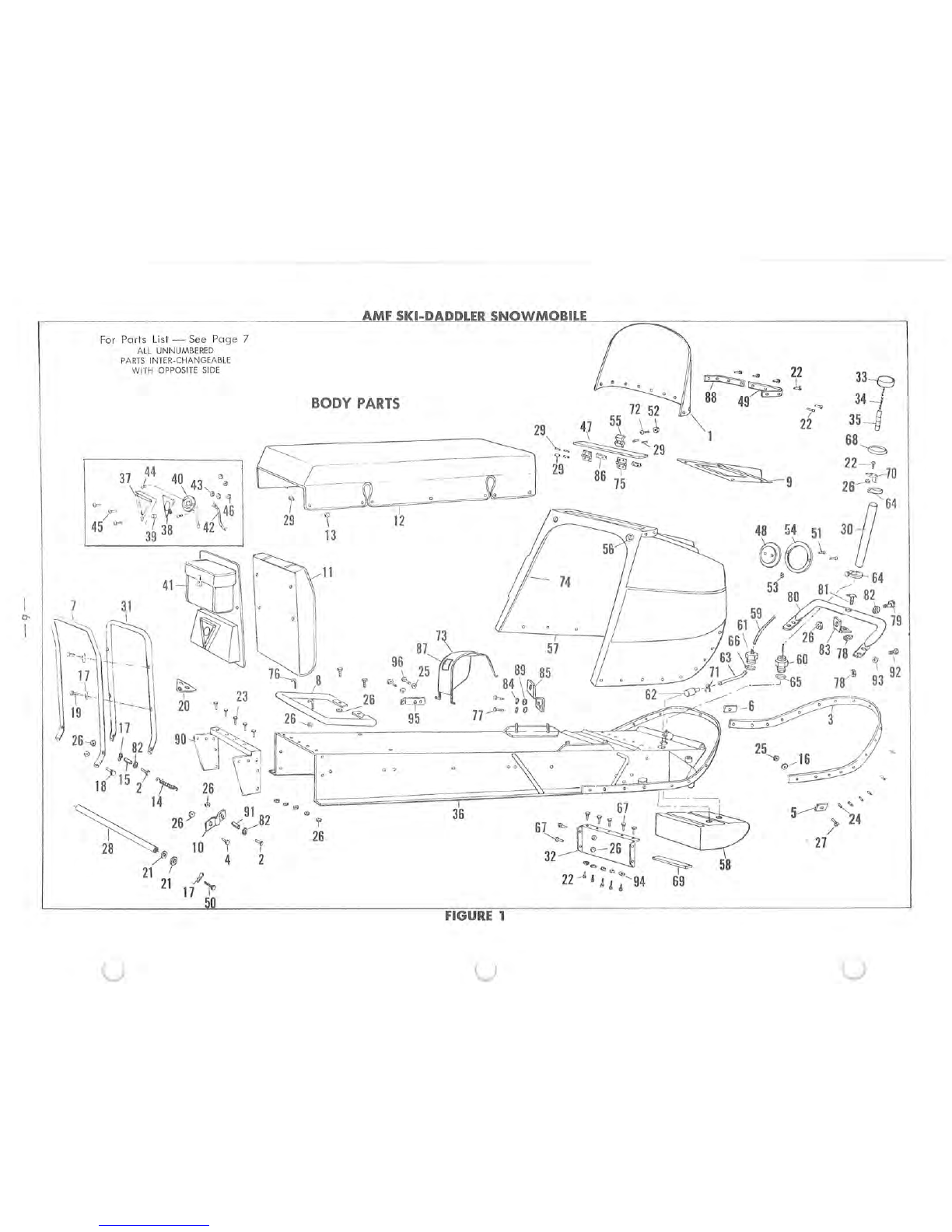
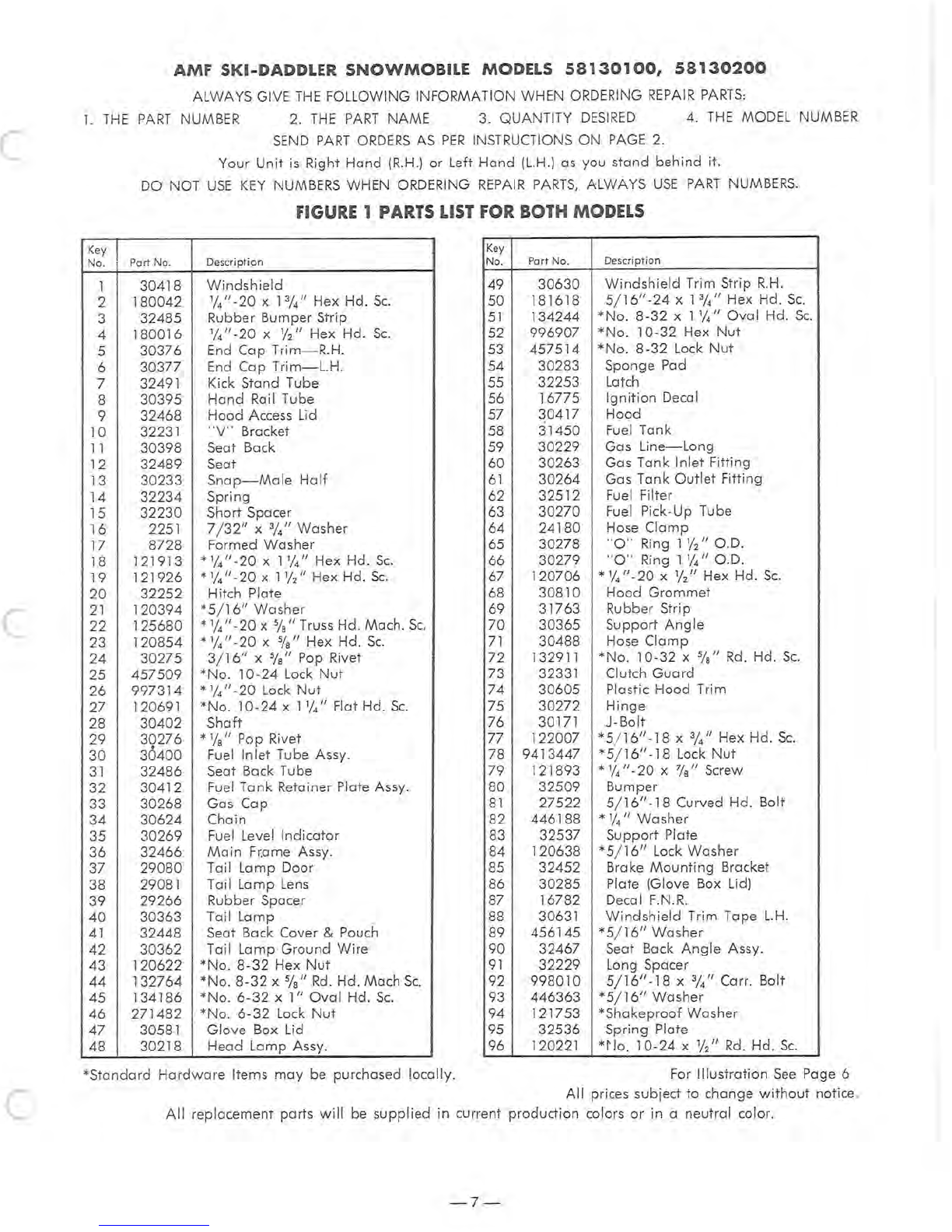
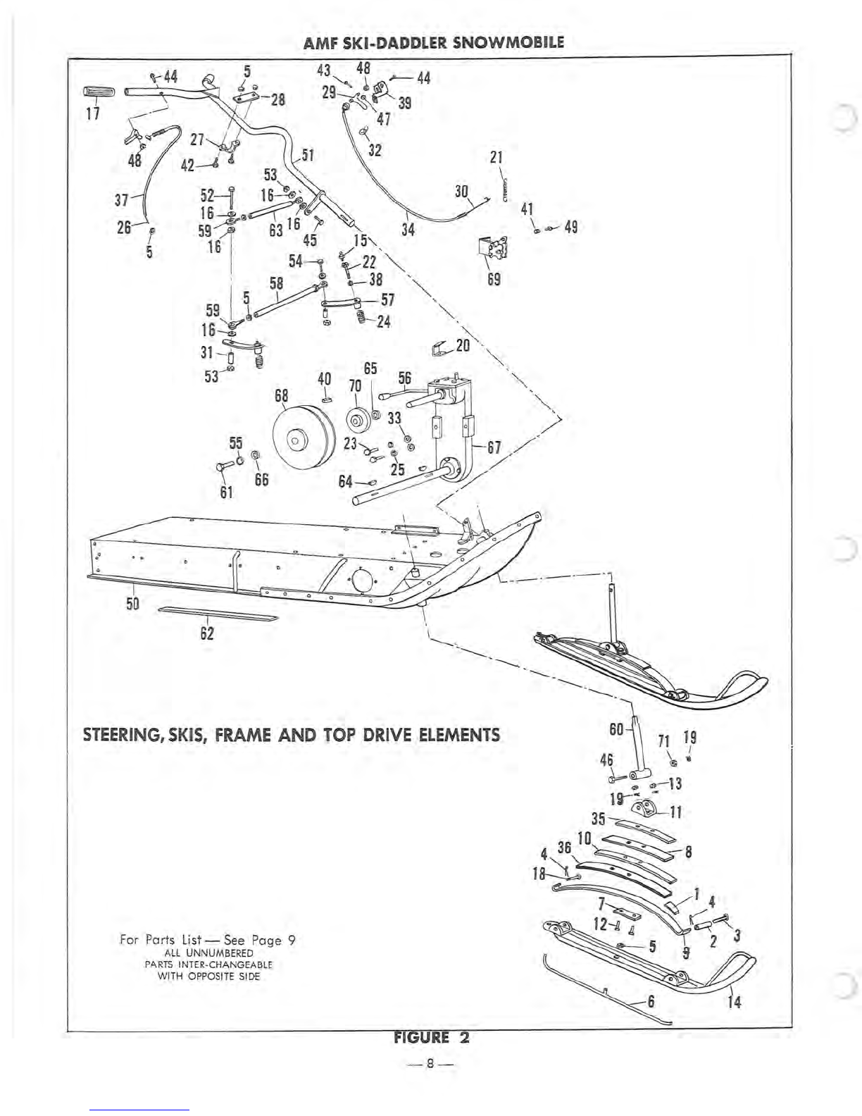
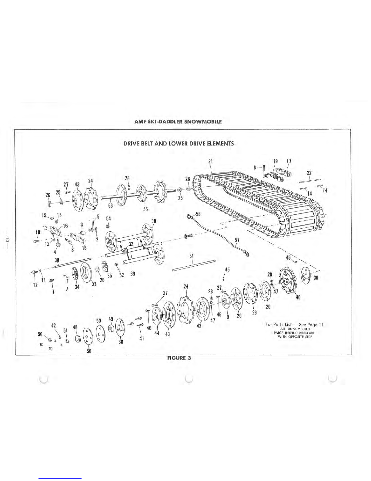
manuals.online logo
Brands
  1. Home
  2. •
  3. Brands
  4. •
  5. AMF
  6. •
  7. Offroad Vehicle
  8. •
  9. AMF Ski-Daddler 5813-0100 User manual

AMF Ski-Daddler 5813-0100 User manual

This manual suits for next models

1

Other AMF Offroad Vehicle manuals

AMF 5812-0300 User manual

AMF

AMF 5812-0300 User manual

AMF 1970 SKI-DADDLER SD15M21 A Quick start guide

AMF

AMF 1970 SKI-DADDLER SD15M21 A Quick start guide

AMF SKI-DADDLER Quick start guide

AMF

AMF SKI-DADDLER Quick start guide

AMF MARK 23 (SD18E24A) Quick start guide

AMF

AMF MARK 23 (SD18E24A) Quick start guide

Popular Offroad Vehicle manuals by other brands

Polaris Sportsman 570 EFI owner's manual

Polaris

Polaris Sportsman 570 EFI owner's manual

Polaris RANGER XP 1000 EPS 2018 owner's manual

Polaris

Polaris RANGER XP 1000 EPS 2018 owner's manual

Yamaha Tri Moto 125 Service manual

Yamaha

Yamaha Tri Moto 125 Service manual

APRILIA QUASAR 100 manual

APRILIA

APRILIA QUASAR 100 manual

Yamaha YFM350X Warrior owner's manual

Yamaha

Yamaha YFM350X Warrior owner's manual

Polaris RZR 900 owner's manual

Polaris

Polaris RZR 900 owner's manual

Baja motorsports ATV 90 Setup instructions

Baja motorsports

Baja motorsports ATV 90 Setup instructions

Suzuki LT-A700X owner's manual

Suzuki

Suzuki LT-A700X owner's manual

Ski-Doo SCANDIC WT Operator's guide

Ski-Doo

Ski-Doo SCANDIC WT Operator's guide

Polaris Sportsman 550 XP EPS owner's manual

Polaris

Polaris Sportsman 550 XP EPS owner's manual

Arctic Cat 120 sno pro Operator's manual

Arctic Cat

Arctic Cat 120 sno pro Operator's manual

Yamaha RS90PB owner's manual

Yamaha

Yamaha RS90PB owner's manual

Arctic Cat ALTERRA 450 Service manual

Arctic Cat

Arctic Cat ALTERRA 450 Service manual

Dinli DL702 Service manual

Dinli

Dinli DL702 Service manual

Polaris RZR XP 1000 Service manual

Polaris

Polaris RZR XP 1000 Service manual

Polaris Sportsman 9922233 owner's manual

Polaris

Polaris Sportsman 9922233 owner's manual

Yamaha SXV70ML owner's manual

Yamaha

Yamaha SXV70ML owner's manual

Ski-Doo SKANDIC Operator's guide

Ski-Doo

Ski-Doo SKANDIC Operator's guide

manuals.online logo
manuals.online logoBrands
  • About & Mission
  • Contact us
  • Privacy Policy
  • Terms and Conditions

Copyright 2025 Manuals.Online. All Rights Reserved.

:.v~~
~S
NOWMOBILE
MODELS
5813-0100
5813-0200
PARTS
AND
SERVICE
MANUAL
AMERICAN
MACHINE
&
FOUNDRY
COMPANY
CONSUME
R
PRODUCTS
SALES
DIVISION
PARTS
&
SE
RVICE
DEPARTMENT
Whiteford
Road,
York.
Pennsylvania
17402.
Area
Code
717
848-1177
PART
NO.
37951
The
following
information
is
for
Models
58130100
and
58130200
TABLE
OF
CONTENTS
Page
WARRANTY
AND
TABLE OF CONTENTS
..
.......
. 2
TO REMOVE DRIVE
SPROCKETS
................
3
BRAKE ADJUSTMENT
...............
'..........
3
DRIVE
BELT
ADJUSTMENT
......................
4
CARBURETOR-
MODEL
5813
...................
4
WIRING
DIAGRAM
.....................
....
..
5
BODY
PARTS
. . . . . . . . . . . . . . . . . . . . . . . . . . . . . .
..
6
BODY
PARTS
LIST
. . . . . . . . . . . . . . . . . . . . . . . . . .
..
7
SKIS
AND
STEERING . . . . . . . . . . . . . . . . . . . . . . . .
..
8
SKIS
AND
STEERING
PARTS
LIST. . . . . . . . . . . . . . . .
..
9
DRIVE TRACK
...................
...
..........
10
DRIVE TRACK
PARTS
LIST
......
..
...........
.
...
11
ENGINE, ElECTRICAL,
AND
FUEL
ELEMENTS
........
12
Page
ENGINE, ELECTRICAL,
AND
FUEL
ElEMENTS
PARTS
LIST
................................
13
CLUTCHES
..................................
14
TRANSMISSION
.....
.
.........
.
....
.
........
15
BLOCK
AND
HOOD
..........................
16
BLOCK
AND
HOOD
PARTS
LIST
..................
17
FLYWHEEL,
MAGNETO,
AND
PARTS
LIST
..
........
18
CRANKSHAFT
AND
PARTS
LIST
...
..
.............
19
GENERATOR, SOLENOID,
AND
PARTS
LIST
..
.
......
20
MANIFOLD,
MUFFLER,
AND
PARTS
LIST
........
.
...
21
CARBURETOR-MODEL
5813
...
................
22
ENGINE OPERATING INSTRUCTIONS
.............
23
WARRANTY
FLAT
RATE
LABOR SCHEDULE
...
.
.....
27
-2-
c
All
information
in
the
preceding
section
re
lative
to
Models
5811, 5812,
58
14,
and
5815,
apply
to
Model
5813
except
the
inf
ormation
under
POWER TRAIN
on
pages
6
and
7,
BRAKE ADJUSTMENT
and
TO
REMOVE
DRIVE SPROCKETS on
page
8,
and
DR
I
VE
BE
LT
A D-
JUSTMENT on
page
6.
TO
REMOVE
DRIVE
SPROCKETS
1.
Remove
the
battery
from
the
sled. Remove cables
from
batte
ry
termina
l
s.
Remove
battery
hold-down
fasteners.
2. Place
rear
of
sled
on
kick:
stand.
3. Release
track
tensi
on
by
r
emoving
both
right
hand
and
left
hand
adjuster
plates.
Remove
all
fasten-
ers
holding
adjuster
pl
ates
to
the
frame
(See
Figur
e
1).
FASTENERS
ADJUSTER
PLATE
Figure
4. Remove
th
e t
hr
ee screws, l
ock
washers,
and
nuts
that
hold
the
bearing
retainer
to
the
right
side
of
the
sled
(See
Figure 2).
5.
Tu
rn sled
up
on
its
right
side.
With
the
sled
on
it
s
right
si
de,
the
grease
in
the
gear
case
will
not
run
out
as
much
as
it
would
if
the
sled
were
on
its
left
side.
6. Remove lacer
pins
from
the
drive
track
by
bend-
ing
the
ends
straight
and
pulling
them
out.
DRIVE
SPROCKETS
SET
SCREW
BEARING
RETAINER
Figure 2
7. Pull
belt
to
one
side
so
you
can
gain
access
to
the
driv
e sprockets.
8. Remove
the
set screw in
the
collar
at
both
ends
of
the
drive
shaft.
There is a notch in each
collar.
In-
se
rt a
punch
into
the
notch.
Tap
the
punch
lightly
to
loosen
the
collar
(See
Figur
e 2).
9. Remove
the
three
screws
which
secure
the
chain
case cover
(S
ee
Figure
2
1.
10. Re
move
the
bolt
and
washer
from
the
end
of
the
driv
e
shaft
(See
Figure
3).
Tap
on
the
drive
sproc-
kets
with
a
hammer.
Tap
them
to
the
right
side
. This
will
free
the
dr
ive
shaft
from
th
e
gear
shaft
.
11. Loosen set screws
which
hold
the
drive
sprockets
in
pla
ce.
Slide
them
off
the
left
end
of
the
drive
shaft.
12. Replace
or
repair
sprockets.
13.
Reas
s
emble
in
opposite
order.
14.
When
r
ep
lacing
the
drive
shaft
into
the
gear
case,
align
the
large
s
procket
and
the
spacer behi
nd
it
with
your
finger
be
fore
inserting
the
drive
s
haft
(Se
e Figure
4).
Insert
shaft
and
align
notches
on
the
end
of the
dr
ive
shaft
with
those
on
the
sprocket
in
the
gear
case.
Follow
in
s
tructions
und
er TRACK
ALIGN-
MENT,
and
TRACK TENSION ADJUSTMENT
wh
en reas-
sembly
is
co
mpleted.
BOLT
AND
WASHER
Figur
e 3
BRAKE
ADJUSTMENT
Th
e
brake
on
this
unit
is a
disc
caliper
type.
Take
the
fo
llow i
ng
steps
to
adjust:
1.
If
the
brake
is t
oo
loo
se
and
needs
tightening,
loosen
the
tw
o
allen
sc
rew
s as s
hown
in
Figure 5. Pull
brake
cable
tight
and
tight
en
all
en scre
ws.
2.
If
further
adjustm
e
nt
is nee
ded,
remov
e cotter
pin
from
the
castle
nut
on
the
brake
arm
and
tight
en
castle
nut
down
until
the
brake
pad
s
just
drag
on
the
-3-
Figure 4
brake
disc. Then
back
the castle nut off
one
notch
and
reinstall cotter pin (See Fi
gure
5).
3.
If
brake
is
too
tight
reverse
the
above
procedure.
DRIVE
BELT
ADJUSTMENT
Figures 6
and
7
show
two
cut-
away
views
of
the
chain
and
gear
case.
If
drive
belt
is t
oo
loose, loosen
the
two
fasteners
marked
"A"
in
Figures 6
and
7.
Fas
tener
s
are
l
ocated
on
the
inside
of
the
gear
case
just
above
the
frame. Loosen
the
fasteners
marked
"B"
in
Figures 6
and
7. They
are
located
at
the
bottom
of
the
gear
case
on
the
inside. Access to
these
~
Fi
gure
5
fasteners
is
obtained
by reaching
underneath
the side
of
the sled. With
the
fasteners
loose,
the
gear
case
can
be
moved
approximately
1/4
in
ch
forward
or
back
-
ward.
Move the
gear
case
forward
to
tighten
the
drive
belt
and
move it
backward
to
lo
ose
n
the
belt
.
When
adjustment
is
complet
ed,
tighten
fasteners
mark
ed
"A"
and
"B"
as
shown
in
Fi
gures
6
and
7.
Figure 6
Figure 7
CARBURETOR
ADJUSTMENTS
IT
IS
IMPORTANT NOT TO
FORCE
ADJUSTMENTS
INTO
SEATS.
The single
carburetor
used
is
a Tillotson
Model
HR
Carburetor. For
best
results
the
engine
s
hould
be
warm
when
fina l
carburetor
adjustments
are
made
.
Figure 8
shows
the
left
side
of
the
carburetor
and
Figure 9
shows
the
right side.
1.
STARTING A
COLD
ENGINE-
Close
choke
and
crank
engine.
After the e
ngine
starts
move
the
choke
to
the
open
position.
2. STARTING A WARM ENGINE-
It
should
be
started
with
the
choke
open.
The choke
is
s
hown
in
Figure 8.
3.
TO
ADJUST
CARBURETOR
-
Turn
in
high
speed
jet
all
the
way,
(DO NOT
FORCE)
Then
open
11/4
turns
as
shown
in
Figure 8.
When
eng
ine is
warm
place unit
on
ki
cks
tand
and
slowly accelerate to high
speed
. Turn high
speed
ad-
-4
-
c
c
justment
needle
in
to
the
point
where
the
engine
runs
the
fastest
and
smoothest,
then
open
needle
(turn
out
1/4
turn).
.
Turn in
the
idle
mixture
screw
all
the
way
(DO NOT
FORCE)
.
Open
one
full
turn
as s
hown
in
Figure
8. This
adjustment
controls
the
mixture
at
idling
speeds. A
lean
idle
mixture
will
cause
poor
acce
leration.
Adjust
the
idle
.
speed
screw
shown
in
Figure
9.
Keep
idl
e
Figure
8
speed
slower
than
clutch
engaging
speed
(approx
.
1750
-
2000
RPM).
NOTE:
Figure
9
also
shows
a
throttle
wire
adjustment
collar
and
screw. Remove
carburetor
air
cleaner.
De-
press
the
throttle
control.
If
this
does
not
open
the
throttle
plate
completely,
loosen
the
throttle
wire
adjust
-
ment
screw
and
readjust
to
open
throttle.
Figure
9
REPAIRMAN'S
REFERENCE
WIRING DIAGRAM
The
wiring
diagram
shown
here
is a tec
hnical
ex
-
planation
of
the
circuitry
on
this
unit.
It
is
intended
for
use
by
repairman
or
owners
capable
of
reading
and
using
wiring
diagrams.
The
various
component
parts
have
been
lab
e
led
. See
your
Service
Dealer
for
part
numbers,
price
and
o
rd
ering
NOTE,
ALL
WI
RES
ARE
TO
BE
NO.
18
GA
.
STRAN
C'
cD
WITH
THERMO·PLASTIC
COVERING.
IGNITION
SWITCH
(RED)
\
15
AMP
FUSE
(BLACK)
(RED)
(GREEN)
(YELLOW)
information.
Also
see
your
Service
Dealer
for
available
Service
Manual.
We
recommend
that
unless
you
are
fully
qualified
to
make
repairs
on
the
electrical
system
on
this
unit,
you
take
it
to
a
competent
repairman
for
such
work
or
adjustments.
SOLENOID
o - (BLACK)
WIRE CABLE
(WHITE)
(RED)
(BLACK)
HOOD
HARNESS WIRE (SERVICE
ONLY)
(BLUE)
GR
OUND
WIRE TAIL LAMP
-
5-
For
Parts
Li
st -
See
Page
7
ALL UNNUMBERED
PARTS
INT
ER
-CH
ANGEAB
LE
WITH OPPOSI
TE
SI
DE
AMF SKI-DADDLER SNOWMOBILE
BODY
PARTS
~...
22
33~
~
....
1 r
88
~
34~
49
",<>""
72
52
7JJ
22
35
29
4{
51.
L
~
~
1
68
'\,-~=""'
?Q
~
~-9
'"u
~
,4
5~
30t
)0
~
"'J!'l-
64
.
-~~
53
80
81
<tt
82~
~
I \
II
)1
59
O~U
..
~~
79
~
·,
L
11
;"u.
,
..
!
I.
. .
666~
Y
~(
~
I I\
'\
If " I
87
7\
57
•
.'
63
\~
~60
83
7847
'1
~
I • - I . 7
~
,8
y
(~
~e'
84
\
~
""
~_~
__
()~
\'Q,~
17
--'-
~
0
l
l
~
26,~
95
>
'.
..
-=-......,.
:w
25
"
' " • -
~
u
r===~--..s;;:":_
~
o:s
/.
/
~26,~J;j~12;
90
t~
':.
'"
~':.l~
~
~@~"
18 15
2..,..,
26
U I _ /
',
y..flI
"
.
~
14
Y'
~
91
82
····?·
3~ 67
~
."
•
.]'
6
1
•
~
,
/,,24
26
r
~~
~
e
~
.
I
27
I
"I?
~
26
0-
26
'1
28
10
I I
32.,
~
58
-(5)
4 2
"'...
I
/' ?
22
_A
~
J
~
~
94
69
21
,R
J ,
21
17
'\'>
50
FIGURE 1
u u u
c
c
c
AMF
SKI-DADDLER
SNOWMOBILE
MODELS
58130100,
58130200
ALWAYS GIVE
THE
FOLLOWING INFORMATION WHEN ORDERING
REPAIR
PARTS:
1.
THE
PART
NUMBER
2.
THE
PART
NAME
3.
QUANTITY
DESIRED
4.
THE
MODEL NUMBER
SEND
PART
ORDERS
AS
PER
INS
TRU
CTIONS
ON
PAGE
2.
Your
Unit
is
Right
Hand
(R.H.)
or Left
Hand
(L.H.)
as
you stand
behind
it.
DO NOT
USE
KEY
NUMBERS WHEN ORDERING
REPAIR
PARTS,
ALWAYS
USE
PART
NUMBERS.
FIGURE 1 PARTS LIST FOR BOTH MODELS
Key Key
No.
Part No. Description No. Part
No
. Description
1 30418
Windshield
49
30630
Windshield
Trim Strip
R.H.
2
180042
1//'
-
20
x 1%" Hex Hd.
Sc.
50
181618
5
/16"
-24
x 13
//'
Hex Hd.
Sc.
3 32485 Rubber Bumper Strip
51
134244
*No
. 8-32 x 1
1/4"
Oval
Hd.
Sc.
4
180016
1/4"
-
20
x
1/
2" Hex Hd.
Sc.
52
996907
*No.
10-32 Hex
Nut
5
30376
En
d Cap
Trim-R
.
H.
53
457514
*No.
8-32 Lock
Nut
6
30377
End Cap
Trim-L.H.
54
30283 Sponge Pad
7 32491 Kick Stand Tube 55 32253 Latch
8
30395
Hand
Rail Tube 56 16775
Ignition
Decal
9
32468
Hood Access Lid 57
30417
Hood
10 32231
"V"
Bracket 58
31450
Fu
el
Tank
11
30398 Seat Back 59
30229
Gas
Line-Long
12
32489
Seat 60 30263 Gas Tank
Inlet
Fitting
13
30233
Snap-Male
Half
61
30264
Gas Tank
Outle
t Fitting
14
32234
Spring 62 32512 Fuel
Fi
Iter
15
32230
Short Spacer 63
30270
Fuel
Pick-Up Tube
16 2251
7/32"
x %"
Washer
64
24180
Hose
Clamp
17 8728 Formed Washer 65 30278
"0
" Ring
llj2"
O.D.
18
121913 *
1/4"
-20
x 1
1/4"
Hex Hd.
Sc.
66 30279 "0 " Ring 1
1/4"
O
.D
.
19
121926
*
1/4"
-
20
x 1
1/
2" Hex Hd.
Sc.
67
120706
*
1//'-20
x
1/
2" Hex Hd.
Sc
.
20
32252
Hitch Plate 68
30810
Hood
Grommet
21
120394
*5
/16"
Washer 69 31763 Rubber Strip
22
125680
*
1//'-20
x %" Truss Hd. Mach.
Sc.
70
30365
Support
Angle
23
120854
*
1/4"
-20
x %" Hex Hd.
Sc.
71
30488 Hose
Clamp
24
30275
3/16"
x %" Pop Rivet
72
132911
*No
.
10-32
x %"
Rd.
Hd.
Sc.
25
457509
*No
. 10-24 Lock
Nut
73 32331 Clutch
Guard
26
997314
*
1/4"
-
20
Lock
Nut
74
30605 Plastic Hood Trim
27 120691
*No.
10-24 x 11/4" Flat Hd.
Sc
.
75
30272
Hinge
28
30402
Shaft
76
30171 J-Bolt
29
30276
*1/8" Pop Rivet
30
30400
Fuel
Inlet
Tube Assy.
77
122007 *5/
16"-18
x %" Hex Hd.
Sc.
78
9413447
*5/16"-18
Lock
Nut
31
32486
Seat Back Tube 79 121893 *
1/4"
-
20
X "'is" Screw
32
30412
Fuel
Tank
Retainer Plate Assy. 80
32509
Bumper
33
30268
Gas
Cap
81
27522
5/16"-18
Curved Hd. Bolt
34
30624
Chain 82
446188
*
1/4"
Washer
35
30269
Fuel Level
Indicator
83 32537
Support
Plate
36
32466
Main
Fr.ame
Assy. 84 120638 *5/
16"
Lock
Washer
37
29080
Tail Lamp Door 85 32452 Brake
Mounting
Bracket
38 29081 Tail Lamp
Lens
86 30285 Plate (Glove Box Lid)
39
29266
Rubber Spacer 87 16782 Decal F.N.R.
40
30363
Tail Lamp 88 30631
Windshield
Trim Tape
L.H.
41
32448
Seat Back Cover & Pouch 89
456145
*5
/16"
Washer
42
30362
Tail Lamp
Ground
Wire
90 32467 Seat Back
Angle
Assy.
43
120622
*No
.
8-32
Hex
Nut
91
32229
Long Spacer
44
132764
*No
.
8-32
x %"
Rd
. Hd.
Mach
Sc.
92
998010
5
/16"-
18 x %" Carr.
Bo
lt
45
134186
*No.
6
-32
x
1"
Oval
Hd.
Sc.
93
446363
*5/16"
Washer
46
271482
*No.
6-32
Lock
Nut
94 121753
*Shakepro
of
Washer
47
30581
Glove
Box Lid 95
32536
Sp
r
ing
Plate
48 30218 Head
Lamp
Assy. 96 120221
*~
10.
10-24
X
1/
2"
Rd.
Hd.
Sc.
*Standard
Hardware
Items
may
be purchased locally. For
Illustration
See
Page 6
All prices subject to change
without
notice.
All
replacement parts
will
be
supplied
in current production colors
or
in a neutral color.
- 7 -
AMF SKI-
DADDLER
SNOWMOBILE
37
26
f
5
o 0 0
50
""""..;:--======~
======
~
I
::3'
62
43 48
44
~J
~
29~~39
d(
47
32
\
-----
-
21
)
~
69
-
----
STEERING,
SKIS,
FRAME
AND
TOP
DRIVE
ELEMENTS
For Parts
Li
st - See
Page
9
ALL UNNUMBERED
PARTS
INTER-CHANGEABLE
WITH
OPPOSITE SIDE
FIGURE 2
-8-
41
\--49
c
c
Key
No. Port No.
1
30247
2 8441
3
28762
4
137185
5
997314
6
32542
7
28764
8
28766
9
28770
10
29645
11
28769
12 995371
13
995224
14
32624
15
706
16
21777
17
28416
18
32174
19
121222
20 30673
21
24347
22
30117
23 120233
24
30149
25
120382
26
32490
27
24054
28 30211
29·
32187
30
32488
31
30251
32
32286
33
120396
34
32487
35
32539
36
32540
AMF
SKI-DADDLER
SNOWMOBILE
STEERING,
SKIS,
FRAME
AND
TOP
DRIVE
ELEMENTS
FIGURE 2 PARTS LIST FOR BOTH MODELS
Key
Description
No. Port No.
Description
Bumper Pad
Spring Roller 37
32292
Cable
Housing
38 120383 Lock
Washer
Spring Pivot
Pin
39
32186
Clamp
*
1/8"
X
1"
Cotter
Pin
40
30575 Square Key
*1/"
,,
_20 Centerlock
Nut
41
25188 Swivel Button
Ski
Wear
Rod
Assy.
Spring Plate
Leaf Spring
Main
Leaf Spring
Middle
Leaf Spring
42
121893
*
1/,,"
-20
x 7/s" Hex Hd.
Sc.
43
445938
No.
6-32
x
%"
Truss Hd.
Sc.
44
142443
No.1
0-32 x 1
%"
Rd.
Hd.
Sc.
45
181643
*%"-24
x 11
/2" Hex Hd.
Sc.
46
995364
%"-24
x
2%"
Hex Hd.
Sc.
Spring
Mounting
Bracket
%"
-24 x 11
/2" Hex Hd.
Sc.
47 32188 Spacer
48
997319
*No.
10-32
Lock
Nut
%
"-24
Slotted
Nut
49
995339
No.
8-32
x
%"
Socket Hd.
Sc.
Ski
and
Wear
Rod
Assy.
Grease Fitting
Spacer Bushing
Hand
Grip
Spring Pivot
Pin
*3/32"
x 3//' Cotter Key
50
32466
Main
Frame Assy.
51
32456
Steering
Handle
& Column Assy.
52 181652 % " -24 x
3"
Hex Hd.
Sc.
53
9415106
* %
"-30
Lock
Nut
54
181650
%"-24
x 2 1
/2" Hex Hd.
Sc.
55 120638
*5
/
16"
Lock
Washer
Brake Spring Bracket 56 32478 Lever Assy.
Spring
Spindle
Bolt
*%"-16
x
1"
Hex Hd.
Sc.
57
30060
Spindle
Arm
58
30403
Tie
Rod
59 30081
Rod
End
Bearing
Spring (Spindle)
*
%"
Lock
Washer
60
30124
Spindle
Tube Assy.
61
180079 5/
16"-18
x
1"
Hex Hd.
Sc.
Throttle Control Cable 62 30228 Foot Pad
"
U"
Strap 63 30561 Drag Link
Column
Support
Plate (Upper)
Thumb
Lever 64 30535 No.
706
Hi-
Pro
Key
65
30576
Washer
(Disc Brake)
Brake
Cable
66 8103 Flat
Washer
Spacer Bushing
Cable
Clamp
*
3/
8"
Washer
67
32480
Apex
Gear
Case Complete
68
30392
Driven Clutch
69 28783 Disc Brake
Housin·g (Brake Cable)
70
28784
Di
sc
Brake
Hub
Leaf Spring
71
32703
%"
-24
Slotted Hex
Nut
Leaf Spring
*Standard
Hardware
Items
May
Be
Purchased Locally For
Illustration
See
Page 8
All
prices subject
to
change
without
notice.
All
replacement parts
wi
II
be supplied in
cu
rrent
production
colors
or
in a neutraI color.
-9-
~
o
I
AMF SKI-DADDLER SNOWMOBILE
DRIVE
BELT
AND
LOWER
DRIVE
ELEMENTS
27
43
~
2~W_~
15
15
~
5
54
~J
3 '
~
10
13
~
~B
,
-h
~
.
'.
,
J,..
-)1:
~~
2
Ih
/
32
12
r
')
18
._
~
~~\
~
---
~~~
W
~5
52
39
-cr
\
...
~
~
26
\
11.a?
::
Q\
3
12
\ j
34
1
u
21
\
'"
- >
____
~..e
--
31
~
45
I
FIGURE 3
u
~
14
For
Parts
List -
See
Page
11
All
UNNUMBERED
PARTS
INTER
-CH
ANGEAB
LE
WITH
OPPOS
IT
E
SIDE
u