Page 4 of 9
26679654
Rev. A
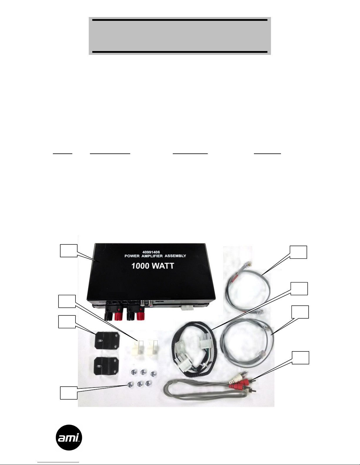
Second Amplifier (1000 Watt) Set Up
The 1000 Watt second amplifier kit is powered by a 1000 Watt Pascal S-PRO2 Class 2
power amplifier. Speaker terminals are provided to connect extension speakers directly to
the amplifiers.
An Audio Output Transformer kit (part number 22180806) is available if your installation
uses 70 volt speakers or you need to connect extension speakers using various power
taps.
Ensure that your speaker load does not exceed 500 watts per channel for the 1000W amplifier.
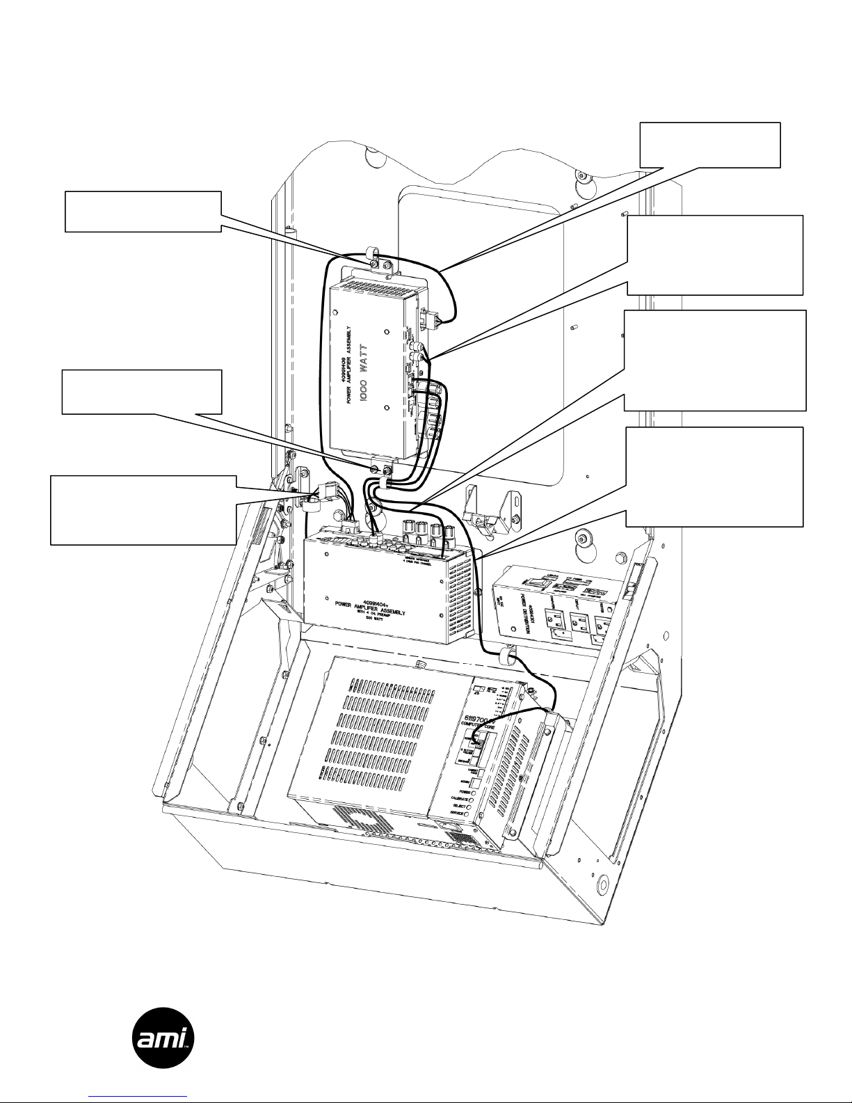
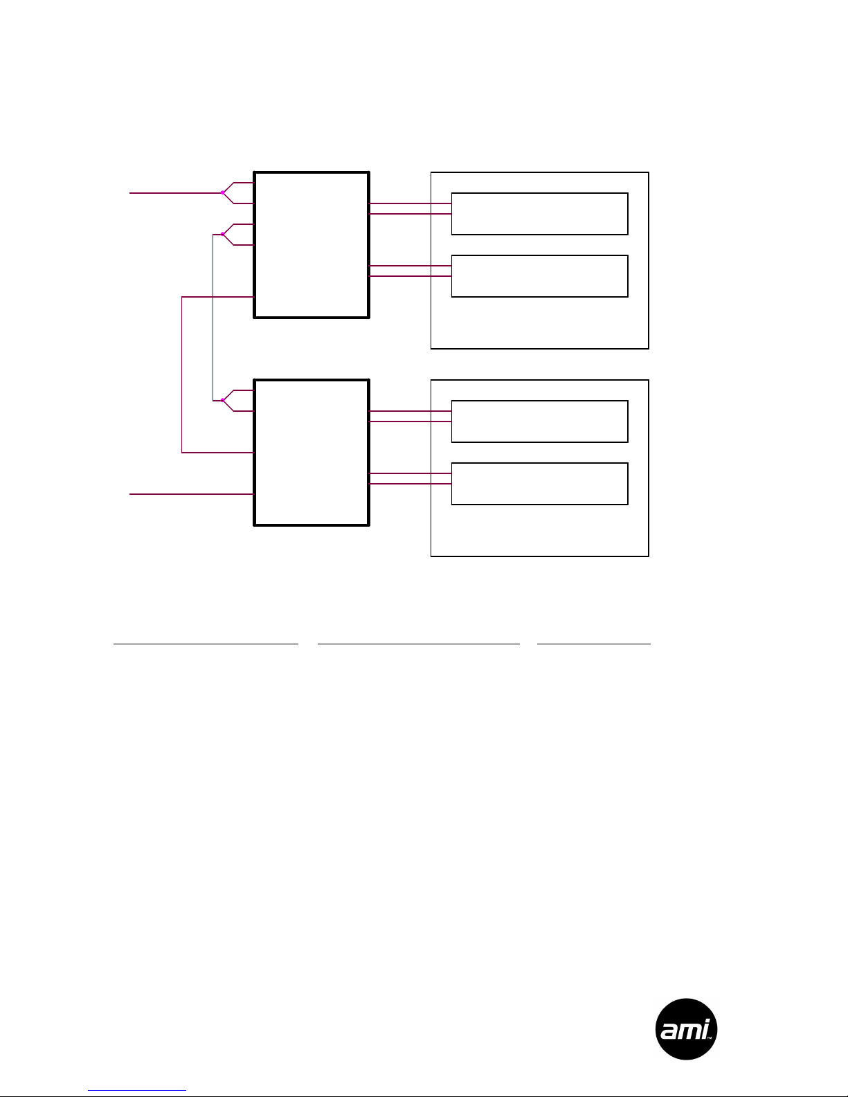
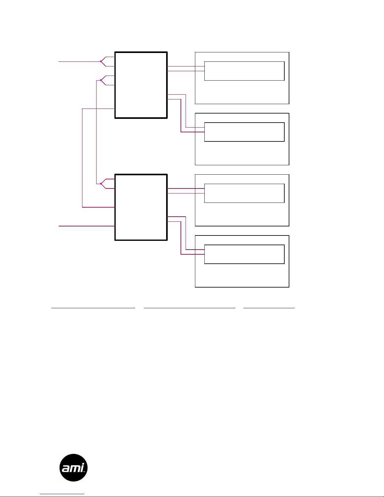
Dual Amplifier Configuration
The installation of a second amplifier brings the total number of driven channels in the
NGX to four. The preamplifier in the primary amplifier is used to drive the inputs of the
second amplifier.
Second Amplifier Indicators
There are three indicator LEDs visible on the front of the secondary amplifier.
POWER – when lit, indicates power is applied to the amplifier
THERMAL – when lit, indicates the amplifier shut down due to overheating
OVERCURRENT – when lit, indicates the amplifier shut down due to a speaker overload
Second Amplifier Switches
MUTING: This switch must be set to the “A” position when the amplifier is used as a
secondary amplifier.
OUTPUT: the Output switch on the front of the 1000 Watt secondary amplifier is used to
select the speaker load. Choose 2 Ohm or 4 Ohm mode. This switch affects only the
secondary amplifier.
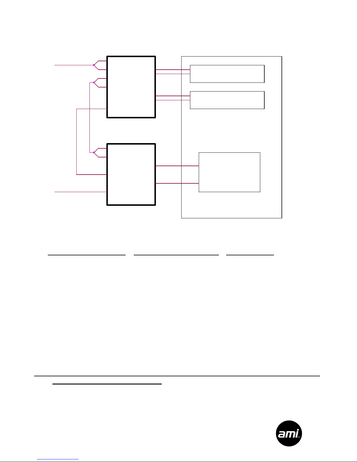
Bridge Mode
The secondary 1000 Watt amplifier can drive speakers in bridge mode. This allows
speaker connections directly across the Channel 1/3– (Black) and Channel 2/4+ (Red)
output terminals. In this configuration, the full 1000 watt amplifier power can be used to
drive appropriate speakers or a sub-woofer. In bridge mode the minimum speaker
impedance is double the OUTPUT switch setting, 4 ohms or 8 ohms. If driving a sub-
woofer, choose one that incorporates a low pass filter and make sure it can handle 1000
watts.