amiad Spin Klin User manual

3” Spin Klin Ext. 910101-000929 / 09.2017 Page 1 of 28
AMIAD WATER SYSTEMS Ltd.
3” Spin Klin Battery
External Source
Automatic back-flush
Serial number:
_______________
Order number:
_______________
Catalog number:
_______________
Filtration degree:
_______________
Tested by:
_______________
Installation and Operation
Instructions
910101-000929/ September 2017

3” Spin Klin Ext. 910101-000929 / 09.2017 Page 2 of 28
AMIAD WATER SYSTEMS Ltd.
3” Spin Klin Battery - External Source - Automatic back-flush
Image is for illustration only
Disclaimer:
Copyright © 2017 Amiad Water Systems Ltd. All rights reserved.
The contents of this document, including without limitation all information and materials, images, illustrations, data, drawings, names and any other such
materials that appear in this document are the sole property of Amiad Water Systems Ltd., including any intellectual property rights, whether registered
or not, and all know-how contained or embodied therein. Amiad may alter, remove or change the Content without any further notice. You may not
reproduce, copy, modify, create derivative works from, sell or participate in any sale of, or exploit in any way, in whole or in part, any of this document or
its content.
The confidential nature of and/or privilege in the file enclosed is not waived or lost as a result of a mistake or error in this file.If you received this file in
This document does not replace any certified drawing, procedure or information provided by Amiad in reference to a specific customer, site or project.
Amiad assumes that all users understand risks involved within this file and/or its attached materials.This document is given in good faith and is not
intended to impose any obligation to Amiad. While every effort has been made to ensure the information in this manual is accurate and complete, we
would appreciate if you can bring any errors or omissions to the knowledge of Amiad or consult Amiad experts or its authorized representatives if you
have any questions.
Amiad Water Systems Ltd. D.N. Galil Elyon 1, 1233500, Israel Tel: 972 4 690 9500 | Fax: 972 4 814 1159 Email: inf[email protected]

3” Spin Klin Ext. 910101-000929 / 09.2017 Page 3 of 28
Table of Contents
1. INTRODUCTION...................................................................................................................................... 4
2. SAFETY INSTRUCTIONS........................................................................................................................... 4
General Safety Instructions.................................................................................................................... 4
Installation.............................................................................................................................................. 4
Commissioning ....................................................................................................................................... 6
Operation and Control ........................................................................................................................... 6
3. STANDARD SYSTEM DIMENSIONS ......................................................................................................... 7
4. DESCRIPTION & OPERATION.................................................................................................................. 8
5. DESCRIPTION AND FILTER OPERATION................................................................................................ 12
6. TECHNICAL DATA ................................................................................................................................. 13
7. INSTALLATION AND OPERATION.......................................................................................................... 14
8. SPIN KLIN SYSTEM MAINTENANCE ...................................................................................................... 17
9. TROUBLESHOOTING............................................................................................................................. 21
10. FILTER PARTS SCHEDULE AND PARTS LIST......................................................................................... 22
11. VALVES - PARTS SCHEDULE AND PARTS LIST ..................................................................................... 23
11.1 STANDARD VALVES PARTS LIST............................................................................................................. 24
11.2 AW VALVES PARTS LIST .......................................................................................................................... 25
11.3 SW VALVES PARTS LIST........................................................................................................................... 22
12. SYSTEM DRAWINGS .................................................................................................................................. 22
13. AMIAD LIMITED WARRANTY.............................................................................................................. 28

3” Spin Klin Ext. 910101-000929 / 09.2017 Page 4 of 28
1. INTRODUCTION
General
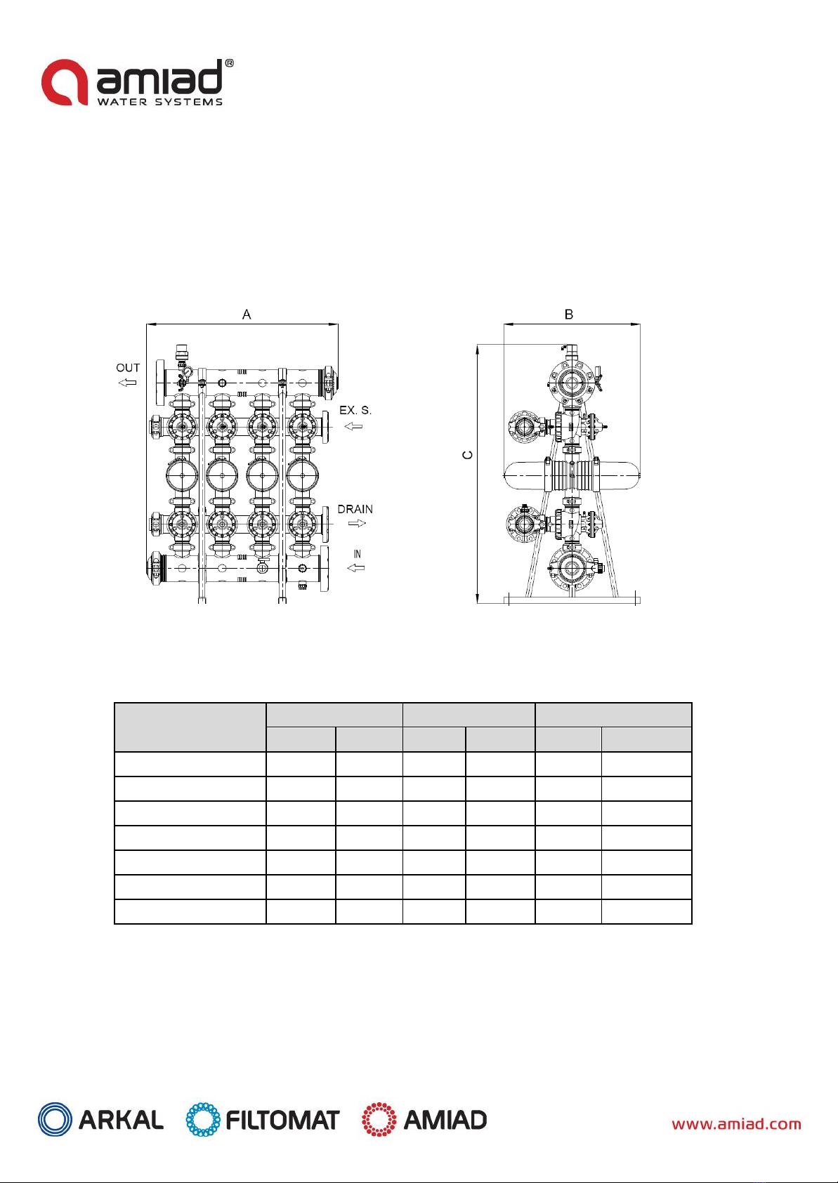
Amiad Water Systems congratulates you for purchasing the 3" Spin Klin battery with external source back-flushing. These
filters are easy to install, use and service; they require no special skills to operate.
For operation and maintenance of this filter, please follow the instructions in this manual.
This 3” Spin Klin battery is an automatic self-cleaning filter battery designed for non-hazardous liquids only and for operation
within the pressure framework specifications.
2. SAFETY INSTRUCTIONS
General Safety Instructions
➢The manufacturer filtration products always operate as components in a larger system. It is essential for the system
designers, installers and operators to comply with all the relevant safety standards.
➢Prior to installation, operation, maintenance or any other type of action carried out on the filter, read carefully the
installation and operation instructions.
➢During installation, operation or maintenance of the filter all conventional safety instructions should be observed to avoid
danger to the workers, the public or to property in the vicinity.
➢The system must be used for non-hazardous liquids only!
➢Please note: The filter enters into a flushing mode automatically, without any early warning.
➢No change or modification to the equipment is permitted without a written notification given by the manufacturer or by its
representative, on the manufacturer’s behalf.
➢Always observe standard safety instructions and good engineering practices whilst working in the filter’s vicinity.
➢Use the filter only for its intended use as designed by the manufacturer, any misuse of the filter may lead to undesired
damage and may affect your warranty coverage. Please consult with the manufacturer prior to any non-regular use of this
equipment.
➢System's cleaning and maintenance shall be carried out only when explosive atmosphere is not present!
Installation
General
➢Install the filter according to the detailed Installation Instructions provided with the filter by the manufacturer and
according to the description given in this manual.
➢Make sure to leave enough clearance, side and top, to enable easy access for future treatments and safe maintenance
operations.
➢The user should arrange suitable lighting at the area of the filter to enable good visibility and safe maintenance.
➢The user should arrange suitable platforms and safety barriers to enable easy and safe access to the filter without climbing
on pipes and other equipment. The user should verify that any platform, barrier, ladder or other such equipment is built,
installed and used in accordance with the relevant local authorized standards.
➢Check and re-tighten all bolts during commissioning and after the first week of operation.
➢Use only appropriate standard tools and equipment operated by qualified operators when installing, operating and
maintaining the filter.
➢When installation is required in hazardous environment sites, underground or high above ground, make sure that the site
design and the auxiliary equipment are appropriate and that installation procedures are carried out in accordance with the
relevant standards and regulations.
➢Ensure walking areas about the installation are slip free when wet.

3” Spin Klin Ext. 910101-000929 / 09.2017 Page 5 of 28
Shipment and transporting
➢Shipping and transporting the filter must be done in a safe and stable manner and in accordance with the relevant
standards and regulations.
➢For shipping, lifting and positioning the filter, use only approved lifting equipment and authorized employees and
contractors.
Electricity
➢Electric wiring should be performed by an authorized electrician only, using standardized and approved components.
➢The system must be installed with suitable electrical earthing that would prevent any electrostatic discharge from the
system.
➢Install a lockable main power cut-off switch close to the control panel.
➢If due to site constraints, the control panel is installed without a clear line-of sight of the filter, an additional lockable power
disconnect cut-off switch should be installed near each filter unit.
➢Installation of the filter should be performed to avoid direct water splashing on the electrical components or on the control
panel.
Pneumatics
➢Install a lockable main cut-off switch, featured with a pressure release mechanism, on the compressed air supply line close
to the control panel.
➢If the control panel is installed far away and there is no eye contact with the filter, a lockable compressed air cut-off switch,
featured with a pressure release mechanism, should be installed near each filter unit.
➢The user should make sure that the compressed air supplied to the filter never exceeds the maximum designated pressure
for this filter. An air-pressure reduction valve should be installed on the compressed air supply line upstream of the filter’s
pneumatic inlet port.
Hydraulics
➢Extra safety devices should be installed on hot water applications to avoid skin burn danger.
➢The user should install a manual Water Cut-off Valve next to the filter’s inlet and outlet ports.
➢In cases where the downstream piping network downstream of the filter is pressurized an additional manual Water Cut-off
Valve should be installed next to the filter outlet port.
➢The user should make sure that the system includes a Pressure Release / Drainage Valve to enable release of residual
pressure prior to any maintenance procedure performed on the filter.
➢The user should make sure that the filter is never exposed to water pressure exceeding the maximum designated pressure
for this filter, if needed a Pressure Reduction Valve should be installed upstream of the filter’s water inlet port.
➢Please note that the maximum working pressure indicated at the filter’s specifications table includes the pressure caused by
fluid hammer and pressure surge effects.
➢it is forbidden to perform any work on the filter before verifying that all pressure has been released from the
system
Civil Engineering
➢Make sure that the filter installation is done by the manufacturer-qualified technicians.
➢Make sure that any civil engineering work at the installation site such as construction, lifting, welding, etc. is done by
qualified workers / technicians / contractors and in accordance with the relevant local standards.
➢While using lifting equipment, make sure that the filter or the lifted part is chained securely and in
a safe manner.
➢Do not leave lifted equipment if there is no necessity. Avoid working below lifted equipment.
➢Wear a safety helmet while using lifting equipment.
➢Make sure that the flooring is sloped for drainage and to avoid accumulation of liquids.

3” Spin Klin Ext. 910101-000929 / 09.2017 Page 6 of 28
Commissioning
➢Read carefully the Commissioning and the First Start-up Operation instructions prior to any attempt to operate the filter.
➢To achieve maximum performance and smooth operation of the filter it is crucial to perform the startup and first operation
procedures exactly as described in this manual.
➢Commissioning the filter should be done by a technician authorized the manufacturer; do not attempt to commission the
filter unaccompanied as this may lead to undesired damage and may affect your warranty coverage.
Operation and Control
➢Do not operate the filter before carefully reading and being familiar with its operation instructions.
➢Observe the safety stickers on the filter and never perform any operation contradicting the instructions given.
➢Never operate or use the filter for purposes other than its original design and operational envelope.
➢The system must be used for non-hazardous liquids only!
➢System's cleaning and maintenance shall be carried out only when explosive atmosphere is not present!
Before any maintenance or non-regular operation
➢Servicing the filter should be done only by technicians authorized by the manufacturer.
➢System's cleaning and maintenance shall be carried out only when explosive atmosphere is not present!
➢Disconnect the filter from the power supply and lock the Main Power Switch.
➢Disconnect the compressed air supply, release the residual pressure and lock the Pneumatics Main Valve.
➢Disconnect the filter from the water system by closing and securing the manual inlet and outlet valves. In cases where the
downstream piping network is pressurized, close and secure the manual outlet valve also.
➢Release the residual water pressure by opening the pressure release / drainage valve.
➢Empty the filter by opening the drainage valve.
➢In hot water systems wait till the filter components cool off to a safe temperature.
➢Place warning signs around the work area, as required by the local standards and procedures.
➢Inspect the filter’s safety stickers and replace any damaged or faded stickers.
Special Note
Before opening the filter lock, check that there is no pressure in the filter.

3” Spin Klin Ext. 910101-000929 / 09.2017 Page 7 of 28
3. STANDARD SYSTEM DIMENSIONS
•Drawing is for illustration only
Description
Length
Height
Width
mm
inches
mm
inches
mm
inches
2-unit battery
824
32.4
1613
63.5
660
26.0
3-unit battery
824
32.4
1613
63.5
660
26.0
4-unit battery
1,074
42.3
1613
63.5
660
26.0
5-unit battery
1,650
65.0
1613
63.5
660
26.0
6-unit battery
1,650
65.0
1613
63.5
660
26.0
7-unit battery
2,470
97.2
1613
63.5
741
29.2
8-unit battery
2,718
107.0
1613
63.5
741
29.2

3” Spin Klin Ext. 910101-000929 / 09.2017 Page 8 of 28
4. DESCRIPTION & OPERATION
Disc Filtration Technology
Amiad Water Systems uses a specially designed disc filtration technology. Thin, color-coded
polypropylene/ nylon discs are diagonally grooved on both sides to a specific micron size. A series of these
discs are then stacked and compressed on a specially designed spine. When stacked, the groove on top runs
opposite to the groove below, creating a filtration element with a statistically significant series of valleys and
traps for solids. The stack is enclosed in corrosion and pressure resistant housing.
During the filtration process, the filtration discs are tightly compressed together by a spring power and
differential pressure, thus providing high filtration efficiency. Filtration occurs while water is percolation from
the outer diameter to the inner diameter of the element. Depending on the micron rating, there are from 18
(in 400 micron discs) to 32 (in 20 micron discs) stopping points in each track, thus creating the unique in-depth
filtration.
Table of Filtration Grades of the Discs and Color Code

3” Spin Klin Ext. 910101-000929 / 09.2017 Page 9 of 28
Spin Klin Technology
Spin Klin Spine - The Core of the Spin Klin Filtration System
The Spin Klin® discs are stacked on the Spin Klin®
spine.
The
discs
are color-coded according to micron size and are assembled to suit
the water filtration requirements. The spine assembly has a spring
compression unit and an internal piston, which operate during alternate
filtration or back-flush modes. Inside the housing the spring and the
pressure
difference compress the discs tightly during the filtration
process, forcing the water to flow between the grooves and
trap
the
solids.
Spin Klin Automatic Back-flush Operation
Activated by an external command
(differ
ential pressure or time)
alternate units of the Spin Klinsystem go
into
back-flush
mode. The
inlet three-way valve closes the inlet to the filter pod and opens
the drain. The outlet three-way valve closes the outlet of the filter
pod and opens the external source. During the back-flush process, the
compression spring is released and the pressure difference is
eliminated
. The spine piston rises, releasing the pressure on the discs.
Tangential jets of clean water are pumped at high pressure in the
opposite direction through nozzles at the center of the spine. The discs
spin free and clear, loosening the trapped solids. Solids are quickly
and efficiently flushed out through the drain.
OUT
BACK-
FLUSH
IN
DRAIN

3” Spin Klin Ext. 910101-000929 / 09.2017 Page 10 of 28
Modes of the filter’s Control valve
Filtration Position:
Inlet valve - Water flows from port [2] (main supply) to port [C] (filter connection). Port [1] (drain water outlet)
is closed by the seal.
Outlet valve - Water flows from port [C] to port [2]. Port [1] is closed by the seal.
Back-flush Position:
Inlet valve - Command pressure is applied to the diaphragm’s control chamber through port [D]. The diaphragm
moves the sealed shaft, port [2] closes, preventing flow to the filter. Port [C] opens, allowing flushing water to
flow from port [C] (filter connection) to the drain [1].
Outlet valve - Command pressure is applied to the diaphragm’s control chamber through port [D]. The
diaphragm moves the sealed shaft, port [2] closes, port [1] opens, allowing flushing water to flow to port [C].
D
2
C
1
Outlet Valve Back-flush Mode
Outlet Valve Filtration Mode
D
2
C
1
D
2
C
1
Inlet Valve Filtration Mode
D
2
C
1
Inlet Valve Back-flush Mode

3” Spin Klin Ext. 910101-000929 / 09.2017 Page 11 of 28
BackFlush
valve
INLET
OUTLET
EX. SOURCE
DRAIN
BackFlush mode
Filter in
3" S.K. Filter
Filtration mode
Filters in
Modes of Operation

3” Spin Klin Ext. 910101-000929 / 09.2017 Page 12 of 28
5. DESCRIPTION AND FILTER OPERATION
During the filtration stage, water flows through the INLET manifold and is distributed through the first
3”x3” back-flush valves into the Spin Klin filters.
The water then passes through the filters' elements to the outlet manifold through the second 3”x3” back-
flush valves for consumer use.
Description of the Back-Flushing Process
The back-flushing process of this system is carried out by external source water; therefore each filter is
equipped with 2 flush valves.
1. The controller transmits an electrical command to the first solenoid according to either differential
pressure or time.
2. The solenoid then sends a pressure command to the back-flush valves, switching them from filtration
mode to back-flushing mode.
3. Filter #1 is then back-flushed with water from the External Water Source. Contaminated water and
impurities flow out through the drain manifold.
4. Upon completion of the allotted back-flush time the controller releases the back-flush command. Filter
#1 returns to filtration mode.
5. Filter #2 then enters back-flushing mode and the process is repeated until all the filters in the system
are back-flushed.
6. After all the filters have been back-flushed the system returns to filtration mode, till the next back-
flush cycle.

3” Spin Klin Ext. 910101-000929 / 09.2017 Page 13 of 28
6. TECHNICAL DATA
Parameters
METRIC
US
Maximum pressure
10 bar (25C)
145 ( 77 °F)
Minimum working pressure
Minimum pressure for back-flush:
400µ-130µ
100µ-70µ
50µ-20µ
1.0 bar
3 bar
3.5 bar
5 bar
14.5 psi
43.5 psi
50.75 psi
72.5 psi
Back-flush flow rate per single spine:
400µ-130µ
100µ-70µ
50µ-20µ
20 m3/hr
22 m3/hr
22 m3/hr
88 gpm
100 gpm
100 gpm
Maximum temperature
60 °C (@4 bar )
158 °F (@58 psi)
PH
4-11
4-11
Construction Materials
Filter Housing & Lid
RPA (Reinforce Polyamide) or RPP (Reinforce Polypropylene)
Disc elements
PP (Polypropylene) or PA (Polyamide)
Backwash valves
RPA (Reinforce Polyamide) or RPP (Reinforce Polypropylene)
Manifolds
PP (Polypropylene)
Seals
NBR or EPDM, (Viton optional)
Control Tubing
PE or PA

3” Spin Klin Ext. 910101-000929 / 09.2017 Page 14 of 28
7. INSTALLATION AND OPERATION
Installation
A. Check for any transport damage (the system operates under pressure!).
B. Make sure that the inlet and outlet flow orientations are correct (shown by arrows on the system).
C. Connect the Inlet the Outlet and the Drain ports together with their valves to the Main Manifolds.
D. Verify that all the covers’clamps are properly closed!
E. Connect and check the water source pressure.
F. Connect the Air pressure source to the solenoid and Accumulator.
Start-up Operation
•If possible, perform a dry test run (once or more) on the system and make sure that all the connections and
wiring are ok.
•Run the system by slowly opening the inlet valve; allow air to vent out of the system through the Air Release
Valve which is mounted on top of the Inlet manifold.
•Once the air is vented, check for any leakage that may happen during transportation and installation.
•If the pressure difference across the filters is high, verify that the flow rate is not too high. An excessive flow
rate through the filter causes excessive pressure loss.
•Open the Air Supply and check the air pressure.
•Manually start a back-flushing cycle and make sure that all the system’s components function correctly.
•If after the back-flushing cycle the pressure difference is not reduced, check that the flow is not too high.
PLC/Control
Note: PLC/Controllers are varied according to the Order.
•Refer to the manufacturer’s handbook before installing the PLC/Controller.
•Make sure that the voltage is correct BEFORE connecting it.
•Check that the ∆P hydraulic switch HIGH and LOW pressure tubes are correctly connected to the appropriate
ports.
•Set the DP Switch to the required ∆P (Recommended ∆P is 5m/ 7PSI according to the site conditions).
•Set the PLC/Controller Back-flush Time to 15 seconds and the Dwell time to 5-10 seconds. These settings may
require adjustment in order to conform to local water conditions. Typically, a 1 to 3 hour interval between
back-flushing cycles is recommended.
•Typically, the Back-flush Cycle Time is used as a backup for the DP switch; any signal that triggers a back-
flushing cycle resets the back-flush cycle timer (including Manual Start command).

3” Spin Klin Ext. 910101-000929 / 09.2017 Page 15 of 28
Control Scheme - External Source for back flush

3” Spin Klin Ext. 910101-000929 / 09.2017 Page 16 of 28
Start-up Operation
A. Gradually open the inlet valve (make sure that the outlet valve is partially open).
WARNING Take precaution while operating the system as it may enter to back-flush mode automatically,
without warning.
B. Check the system assembly and its connections for leaks.
C. Perform a back-flush cycle by disconnecting the low-pressure tube from the differential pressure indicator
(closing the electrical circuit) make sure to re-connect it immediately as the back-flush cycle starts.
D. Verify that the back-pressure reading during back-flushing is according the recommended pressure for your
system specific filtration degree.
E. When the filter is clean, verify that the differential pressure between the inlet and the outlet ports does not
exceed 2m (3 PSI).
F. Check that the differential pressure indicator is set for starting a back-flushing cycle at 5m (7 psi)
G. Perform an additional back-flushing cycle manually by rotating the operation handle (turn clockwise 90⁰)
located on the solenoid valve. Make sure to rotate the handle back to automatic mode once the back-
flushing starts.

3” Spin Klin Ext. 910101-000929 / 09.2017 Page 17 of 28
8. SPIN KLIN SYSTEM MAINTENANCE
Monthly Maintenance
Check the inlet /outlet pressures:
When the pressure differential is above 5m / 7 PSI, activate automatic back-flush of the Spin Klin system.
In the event that the pressure differential remains high, check for possible failures.
Check for leakages from the drain manifold:
When there is a leakage of water to the drain during the filtration stage, check for possible failure of the back-
flush valve seals.
Back-flush controller performance:
Check that the controller timing parameters are correctly adjusted and activate the automatic back-flush cycle.
In the event of a back-flush controller malfunction, check for possible failures.
Cleaning of the Command Filter:
Close the command-filter inlet valve, release the pressure trapped in it and remove the cover. Thoroughly clean
the filtration element, then reinstall the command filter element and cover and open the inlet valve.
Winterization:
To prevent the filter battery becoming damaged during water freezing –drain all the water from the filter battery
and the command filter and leave the drain valve opened.
NOTE:
Before performing any maintenance work on the battery, make sure all water and air connections are
disconnected and that the pressure has been released.

3” Spin Klin Ext. 910101-000929 / 09.2017 Page 18 of 28
Seasonal Maintenance –Cleaning the Discs
When manual cleaning of the discs is required, please
follow the steps described below:
Make sure that system is not under pressure! Release
the clamp and remove the cover (Figures 1, 2)
Unscrew the butterfly-nut on the filtration element
(Figure 3) Remove the tightening cylinder (Figure 4)
Remove the discs (for convenience we recommend
using a plastic bag) (Figures 5, 6)
Tie each set on a string and place them in a cleaning
solutions (HCL, Chlorine, or other) refer to “Cleaning
Recommendations Clogged Filtration Discs”.
Thoroughly wash the discs with fresh water (Figure 7)
Reassemble the discs on the spines; check that the
correct quantities of discs are assembled on the
spine: when the discs are pressed with two hands,
the top disc should be level with the imprinted
circle on the outside of the spine (Figure 8)
Put on the tightening cylinder and tighten the
butterfly-nut, then reassemble the filtercover and
tighten the clamp (Figures 9, 10)
Figure 1
Figure 2
Figure 3
Figure 4
Figure 5
Figure 6
Figure 7
Figure 8
Figure 10
Figure 9

3” Spin Klin Ext. 910101-000929 / 09.2017 Page 19 of 28
Cleaning Recommendations for Clogged Filtration Discs
Water-formed deposits may cause clogging of the filter discs. The formation of these deposits depends on
the quality of the filtered water and environmental conditions like temperature, pH, light, duration of
filtration and more.
Common water-formed deposits are:
•Biological or organic deposits (mostly mucous or oily to the touch, beige, brown or green in color)
•Iron oxide (rust) or other metal oxides
•Carbonates (white or gray deposit)
•Combinations of the above
If these deposits cannot be eliminated by pretreatment of the water, we recommend the following
cleaning procedure:
Material and Equipment
•A well ventilated working place.
•2 small containers (1 liter), 2 large containers (15 liters) and a stirring stick, all resistant to chemicals,
preferably of polypropylene.
•Plastic rope to tie up the disc.
•Sodium Hypochlorite NaOCl - Strong oxidizing liquid, commercial concentration: 10%. Oxidizes and
removes organic and biological deposits.
•Hydrochloric Acid HCl - Very corrosive liquid, commercial concentration: 30%. Dissolves and removes
carbonates, iron oxide, and other deposits.
•Safety equipment: safety glasses, gloves, long pants, long sleeved shirt and shoes.
ATTENTION!
While working with chemicals protect yourself with the necessary safety equipment:
•Safety glasses, gloves, protective clothing
•Work in a well-ventilated area
•Follow the manufacturer’s instructions
Cleaning Organic and Biological Deposits
•Open the filter and remove dirty discs. Attention –Never open the filter before the pressure has
been released.
•Arrange the discs loosely on the plastic rope
•Prepare a 5% Sodium Hypochlorite solution:
1. Pour 5 liters of water into one of the large containers.
2. Add 5 liters of Sodium Hypochlorite (10%) into the water.
•Soak the discs in the solution so that both sides are covered. To achieve maximum cleaning, agitate
the discs several times with a stirring stick.
•Contact time with cleaning solution: up to 8 hours
•Remove the discs carefully from the solution, put them in the second large container and rinse them
very well with clean water before placing them back in the filter.
•We recommend flushing the cleaned discs again in the filter to ensure that all chemical residues are
removed.
The cleaning solution can be used for several sets of discs. As the cleaning activity of the solution deteriorates,
it may be necessary to soak the discs for a longer time.

3” Spin Klin Ext. 910101-000929 / 09.2017 Page 20 of 28
Cleaning Carbonates and Iron Deposits
•Open the filter and remove the dirty discs.
•Arrange the discs loosely on the plastic rope.
•Prepare a 5% Solution of Hydrochloric Acid:
1. Pour 10 liters of water into one of the large containers.
2. Carefully add 2 liters of Hydrochloric Acid (30%) into the water. Soak the discs in the solution so
that both sides will be covered.
PLEASE NOTE: Carbonates react violently with hydrochloric acid (foaming, gas evolution). To achieve
maximum cleaning, agitate the discs several times with a stirring stick.
•Contact time with cleaning solution: 1 - 8 hours.
•Remove the discs carefully from the solution and rinse them well with clean water before placing them back
in the filter.
•We recommend flushing the cleaned discs again in the filter to ensure that all chemical residues are
removed.
The cleaning solution can be used for several sets of discs. It may be necessary to soak the discs for a longer period as the cleaning
activity of the solution deteriorates.
Cleaning Complex Deposits
If the composition of the deposit is not known, perform the following test:
•Take 5 discs for the test.
•Soak 2 discs in a 5% Sodium Hypochlorite Solution.
Preparation of the solution:
Pour 1 cup of water into a small container, then add 1 cup of Sodium Hypochlorite (10% NaOCl).
•Soak 2 discs in a 5% Hydrochloric Acid Solution.
Preparation of the solution:
Pour 2½ cups (= 500ml) of water into a small container, then add carefully
½ cup (= 100ml) of Hydrochloric Acid (30% HCl).
•Keep one disc as a control.
Observe the cleaning process:
If one of the solutions removes all the deposit, clean the discs in that solution according to the
instructions above.
If neither solution removes the deposit completely, continue with the test procedure.
•Remove the discs from both solutions, rinse them well with water and soak them in the second solution:
put the two discs, which have been in the Sodium Hypochlorite Solution, in the Hydrochloric Acid Solution,
and the other way around.
•Check the cleaning process:
If one of the treatments removes all the deposit, clean all the discs following the same two-step
procedure in the exact same order. Rinse the discs well between the two cleaning processes. If the
deposit hasn’t been completely removed, send a set of untreated discs to the laboratory for further
examination.
This manual suits for next models
1
Table of contents
Popular Camera Accessories manuals by other brands

DISCOVER
DISCOVER 14-24-2800 operating manual

First Alert
First Alert SFA250 user manual

Franklin Fueling Systems
Franklin Fueling Systems INCON TSSP-BAT REPLACEMENT PART INSTRUCTIONS

Vivid
Vivid CLT-302R user manual

PROAIM
PROAIM CINEMA Series Assembly manual

Sundstrom
Sundstrom SR 501 EX Maintenance Instruction

PASCO
PASCO EP-3560 Replacement instructions

Platinum
Platinum PT-TPM665-C Quick setup guide

Cyclopital3D
Cyclopital3D Close–up/Macro Adapter forFujiFilm FinePix Real3D... user guide

WIRAL
WIRAL wiral lite user manual

American Dynamics
American Dynamics AD1371 Series installation instructions

Teledyne
Teledyne 7000 Series INSTALLATION PROCEDURE