3
OWR 20 data
Notes
Collector angle/installation
The collector can be installed at
any angle between 0° (horizon-
tal) and 90° (vertical).
Installation is possible on roofs,
on walls, or free-standing. An-
gles between 15° and 75° are
optimal.
Position of the collector pipe
The collector can be installed
with the collector pipe either
vertical or horizontal. However,
the application is optimised
for horizontal installation. It is
not possible to install with the
collector pipe at the bottom.
Filling the system
Do not fill the system in direct
sunlight. Danger of steam ham-
mering!
Flow setting
The standard collector flow setting
can be found in the data table.
Manual bleed valves
Only use manual bleed valves
which are stable at high tem-
peratures, and which have no
plastic parts.
Setting the pressures correctly
For trouble-free operation, it
is essential that the pre charge
pressure in the expansion ves-
sel, and the operating pressure
in the solar system, are set cor-
rectly. Correct dimensioning
and correct connection of the
expansion vessel are just as im-
portant (pp. 17-21).
Automatic bleed valves
We do not recommend auto-
matic bleed valves! If, however,
there is no alternative, automat-
ic bleed valves must always be
installed vertically. A mechani-
cal shut-off in the form of a
suitable stop valve is imperative
(see instructions).
Frost risk
Outdoor pipes with no flow-
through are bound to be at risk
from frost. During installation
care must be taken to keep all
outdoor pipes as short as pos-
sible.
Sensor installation
For trouble-free functioning of
the entire system, the sensor
must be inserted 19 cm into the
provided sensor well in the col-
lector on the input/output side.
Devices/Fittings
For trouble-free functioning of
the entire system, it is impera-
tive to install the devices and
fittings described in the product
documentation.
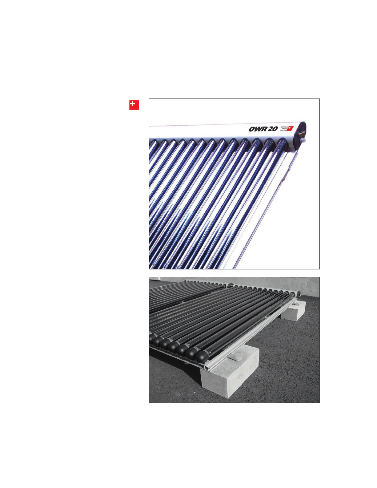
Vacuum test
Reflective tube ends
= vacuum is okay.
Milky tube ends
= vacuum (insulation) damaged.
Notes
Length:
Width:
Height (including frame):
Number of tubes:
Gross surface area:
Aperture area:
Active absorbing area 360°:
Weight:
Total content:
Max. permissible operating pressure:
Recommended volume flow
200 mm
1670 mm
120 mm
20
3.457 m2
1.98 m2
5.46 m2
72.5 kg
3.52 litres
10 bar
1.7 l/min (per module)
Data OWR 20
In addition to the collector frame,
the packaging unit also contains
the associated glass tubes.
These packaging units should be
transported carefully and may not
be dropped or thrown. AMK-Col-
lectra AG cannot extend warranty
cover for improper transport and
will replace defective parts only
against charge.
The packaging units may not be
stored outside.They must be
stored in a dry room and protect-
ed from damage.The temperature
should not be under 15°C and not
above 50°C.The relative air hu-
midity should not exceed 75%.
No hamp seals must be used (e.g.
use high temperature resistant
teflon).
The solar circuit is to be bled thor-
oughly; every circuit must be
flushed separately.
Warning!
Local regulations must be ob-
served during installation!
Packaging, transport
and storage of the
system