amore WMUI281514-F0 User manual


SAFETY NOTICE .......................................................................................................................................................... 4
Installation and Application Considerations................................................................................................................ 5
Important Care Information......................................................................................................................................... 6
Disclaimer.................................................................................................................................................................... 6
IN THE BOX .................................................................................................................................................................. 7
HANDLING AND INSPECTION.................................................................................................................................. 8
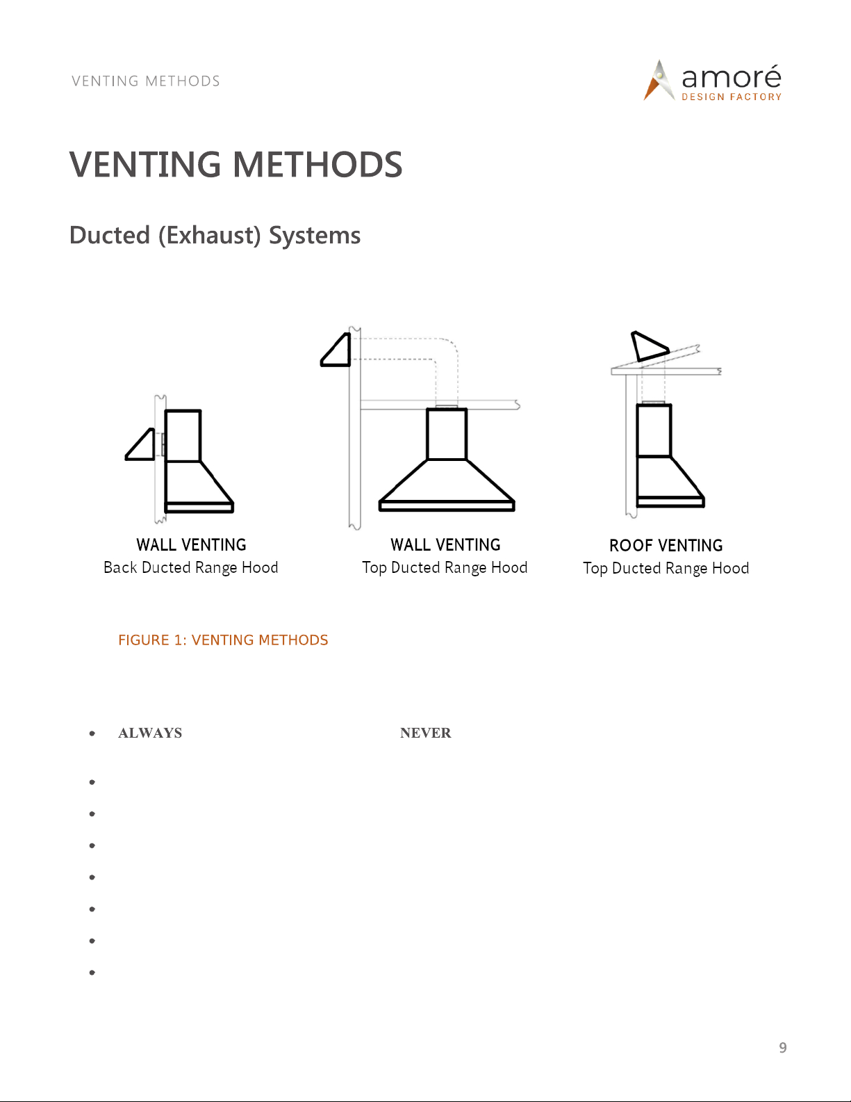
VENTING METHODS................................................................................................................................................... 9
Ducted (Exhaust) Systems........................................................................................................................................... 9
Ductless (Purification) Systems................................................................................................................................. 11
INSTALLATION PREPARATIONS ........................................................................................................................... 12
INSTALLATION.......................................................................................................................................................... 15
Mounting the Insert ................................................................................................................................................... 15
Complete the Installation........................................................................................................................................... 18
OPERATION ................................................................................................................................................................ 20
MAINTENANCE & CARE.......................................................................................................................................... 21
Cleaning Exterior Surfaces........................................................................................................................................ 21
Cleaning Stainless Steel Baffle Filters ...................................................................................................................... 22
Charcoal Filter Change .............................................................................................................................................. 25
Light Bulb Replacement............................................................................................................................................ 25
WARRANTY................................................................................................................................................................ 27

Your safety and the safety of others are very important to us. Always read and obey the safety messages contained in this
manual. The installer should leave this manual with the customer who should retain
future reference.
The installation instructions in this manual are intended for qualified installers, service technicians or persons with
similar qualified background.
Installation and electrical wiring must be performed by qualified professionals and in accordance with all applicable
codes and standards, including fire rated construction.
attempt to install this appliance yourself. Injury could result from installing the unit due to lack of
appropriate electrical and technical background.
Turning any switch ON before completing installation may cause ignition or an explosion.
The range hood insert may have very sharp edges; please wear protective gloves when installing, servicing,
or cleaning unit.
Excessive weight. Three or more persons are required to move and install this range hood insert. Less than
three persons may result in spinal or other serious injury.

Ensure the following to reduce the risk of fire, electric shock, or injury to persons:
These range hood inserts are designed for general ventilating use only. use to exhaust hazardous or
explosive materials and vapors.
The combustion air flow needed for safe operation of fuel-burning equipment may be
operation. Follow the such as published by the
National Fire Protection Association (NFPA), and the American Society of Heating, Refrigeration and Air
Conditioning (ASHRAE), and the local code authorities.
Before installation, servicing or cleaning the unit, switch OFF the power at the service panel and lock the service
panel to prevent power from being switched ON accidentally.
Ducted fans always be vented outside. vent exhaust into spaces between walls, crawl spaces,
ceiling, attics, or garages.
Use only metal smooth ductwork and smooth gradual turn elbows. use flexible ductwork or sharp
angle turn elbows.
Sufficient air is needed for the proper exhausting of gases through the duct to prevent back drafting.
ASHRAE residential ventilation standard 62.2 limits exhaust fans (total) to a maximum of 15 CFM per 100
square feet of living space, unless a back drafting test is performed or make up air is provided. Consult a local
HVAC engineer for make up air evaluation.
When cutting into the wall or ceiling, be careful not to damage electrical wiring or other hidden utilities.
All electrical wiring must be properly installed, insulated and grounded using UL approved accessories by a
licensed electrician.
The range hood insert be grounded using the green wire of the supply.
Check all joints on ductwork to ensure proper connection and all joints should be taped with silver tape.

Use this unit only in the manner intended by manufacturer. If you have any questions, contact the dealer.
Always turn the range hood ON 5 minutes before cooking to begin the flow of air.
Clean ventilation filters frequently.
allow grease to accumulate on fan, filter, or baffles.
The manufacturer and/or the distributor/reseller decline all responsibility and damages in the event of a failure to observe
the instructions given here for installations, maintenance, and suitable use of the product. The manufacturer and/or
distributor/reseller will not be held responsible for any damages to personal property or real estate or any bodily injuries
whether caused directly or indirectly by the range hood insert. The manufacturer and/or the distributor/reseller further
decline all responsibility for injury due to negligence and the warranty of the unit automatically expires due to improper
maintenance.
Range hood inserts and installation conditions vary by situation. Each installation of our product must be managed and
executed by an experienced professional. This installation guide serves only general and typical situations. Please contact
your dealer with any questions.

Each box contains the following items.
Refer to HANDLING AND INSPECTION (page 8) for important information before removing items from
the box.
1 Ziplock bag containing:

Remove all rings, watches, belt buckles, jewelry, and clothing with metal buttons or snaps to prevent
damage to range hood insert.
Use the cotton gloves provided when handling the range hood insert to prevent scratches and to aid grip.
Once the installation area is prepared and you are ready to commence installation, remove the range hood insert
from its carton and place it on a clean, soft blanket.
remove the range hood insert from its carton until you are ready to install it.
Inspect the range hood insert carefully for any damage or imperfections before you begin the installation. If any
damage or imperfects are discovered, return the range hood insert to its carton and call your dealer
IMMEDIATELY. Do not install a damaged range hood insert.
remove permanently affixed labels, warnings, or plates from the product. This may void
the warranty.
Locate the filters which will be packed separately.

Venting systems can terminate either through the wall or roof (see FIGURE 1). To vent through a wall a 90-degree elbow
is required for top-ducted range hoods.
Ensure the following principles when designing and installing ductwork (refer to FIGURE 2, page 11):
exhaust the ductwork to the outside. terminate or exhaust ductwork into spaces between
walls, crawl spaces, ceiling, attics, soffits, or garages.
Use metal / aluminum ductwork only.
For the 600 CFM exhaust blower system a minimum of a 6-inch diameter duct system must be installed.
For the 1200 CFM exhaust blower system a minimum of a 10-inch diameter duct system must be installed.
Ensure the opening of the damper is equivalent to the open area of the duct.
If a long duct run is required, increase the duct size.
Fasten all connections with sheet metal screws and tape all joints with certified Sliver Tape.
Use caulking to seal external wall or roof opening around cap.

Reduce turns or transitions to a maximum of two if possible (or use the lowest number possible). Install them as
far as possible from the opening and as far apart as possible from each other.
Limit the calculated length of the duct system to 50 feet.
The calculated length is determined as follows:
1ft of straight duct = 1ft
90-degree elbow = 9ft
45-degree elbow = 5ft
Caps = 0ft (do not contribute to the calculated length of the system)
For example, if a duct system has 25ft of straight duct, two 90 degree elbows, one 45 degree elbow
and one roof cap, the calculated length of the duct system would be: 25ft + 9ft + 9ft + 5ft + 0ft =
48ft.

In ductless system installations, the hood insert provides a purification function instead of exhausting as in the ducted
hood system. Fumes and exhaust from cooking is drawn and filtered by a set of charcoal filters. The air is purified and re-
circulated back into the room.
The design incorporates a set of charcoal filters and an air-diverter in addition to the standard aluminum filter sets that
exist in the vented hood system. The standard stainless filters are intended to capture residue from the cooking, the
charcoal filters help to purify the fumes exhausted from the cooking, and the air-diverter redirects the filtered clean air
back into the room.

Put a thick, protective covering over the countertop/cooking surface to protect it from damage or dirt.
Remove any hazardous objects from the work area.
Verify that the insert cut-out is properly dimensioned under your cabinet or hood structure (SEE FIGURE 3)

Verify the proper mounting height of the range hood insert (SEE FIGURE 4).
The recommended heigh
the cooking surface, the hood
capture of heat and grease.

Locate the electrical power inlet hole on the side of the range hood insert (SEE FIGURE 5).
Disconnect the main electric power, prepare and run a 115 volt, 15 amp electrical cable to the rang
mounting location.
Electrical wiring must be performed by qualified professionals and in accordance with all
applicable codes and standards, including fire rated construction.
Mark the location of the duct entrance in the ceiling or wall. Use a drill and saber saw or keyhole saw to cut the
opening for the duct.
Install the ductwork from the ceiling or wall to the exterior of the house.
Refer to the ductwork requirements listed in VENTING METHODS, page 9.

Once the INSTALLATION PREPARATIONS (page 12) have been made, follow the installation steps that apply to your
installation:
Do not perform work on any live electrical system. Disconnect
the main electrical supply before installing this range hood. Touching electrical connectors or other
exposed electrical circuitry inside the range hood when energized could result in death, serious bodily
injury, or property damage.
The range hood insert may have very sharp edges; please wear protective gloves when installing,
servicing, or cleaning unit.
Excessive weight. Three or more persons are required to move and install this range hood insert. Less
than three persons may result in spinal or other serious injury.
Lift the range hood insert up into the cut-out under the cabinet or hood structure (SEE FIGURE 6)

Once inserted, use customer provided hardware to secure the flange to the mounting location using the flange
perimeter mounting holes (SEE FIGURE 7)
Ensure the range hood insert is secured to with appropriate hardware for your selected mounting
location.
attempt to install this appliance yourself. Injury could result. Installation and must be
performed by qualified professionals.
The quantity of flange perimeter mounting holes will vary by insert size. Be sure to secure the
insert using

Install the ductwork between the wall or ceiling and the starter collar on the hood. Fasten connections with sheet
metal screws and tape joints with certified Sliver Tape to secure and ensure the connection is airtight.
Extraction performance will be affected and may result in excessive noise if the ductwork
connection is not airtight.
Insert blower orientation is preset at factory, but can be changed from back ducted to top
ducted (and vice versa) at job site if necessary.
Continue to , next page.

remove permanently affixed labels, warnings, or plates from the product. This may void the
warranty.
Extend the electric power cable through the range hood insert and into the wiring box. Make sure the power
cable is secured in the wiring box with an UL rated clamp.
Referring to the Wiring Diagram displayed in FIGURE 8, connect the black and white wire of the power cable to
the blank locations on the terminal block. Make sure:
the black wire is terminated opposite the existing black wire on the terminal block.
the white wire is terminated opposite the existing white wire on the terminal block.
the green wire from the electric power cable should be connected to the green screw in the wiring
Electrical wiring must be performed by qualified professionals and in accordance with all
applicable codes and standards, including fire rated construction.

Install the stainless steel baffle filters as follows:
Angle the baffle filter and insert front edge into front channel of hood (FIGURE 9).
Bring up the rear edge of baffle until it clears the back edge of hood (FIGURE 10).
Slide the baffle filter backward clearing the catch and rest securely on back edge of hood (FIGURE 11).

put your hands into the fan housing while the fan is operating. Danger of bodily injury.
This appliance is not to be used by persons (including children) with reduced physical, sensory, or mental
capabilities, or lack of experience and knowledge, unless they have been given supervision or instruction
concerning the use of the appliance by a person responsible for their safety. Children should be supervised
to ensure they do not play with the appliance.
Turn the knob marked clockwise until you hear a click. The first
position after the click is the lowest speed for the blower. Continuing to
turn the knob clockwise will increase the speed of the blower.
Turn the knob marked counterclockwise until you hear a click.
Turning the knob counterclockwise also decreases the speed of the blower.
Always turn the range hood ON 5 minutes before cooking to
begin the flow of air, and OFF 5 minutes after cooking to
ensure gases and fumes are properly exhausted/purified.
Turn the knob marked clockwise until you hear a click. The first
position after the click is the highest brightness. Continue to turn the knob
clockwise to lower the brightness.
Turn the knob marked counterclockwise until you hear a click.
Turning the knob counterclockwise also increases lights to maximum
brightness.
This manual suits for next models
55
Popular Ventilation Hood manuals by other brands

FALMEC
FALMEC Plane Top wall FFPLN36W5FS-R Instruction booklet

Kleenmaid
Kleenmaid RH12 Instructions for use and warranty details

ILVE
ILVE X301ISL Series instruction manual

Monogram
Monogram ZV800 installation instructions

KOBE
KOBE CH22 SQB-5 Series Installation instructions and operation manual

Robam
Robam CXW-200-A812 Operation manual