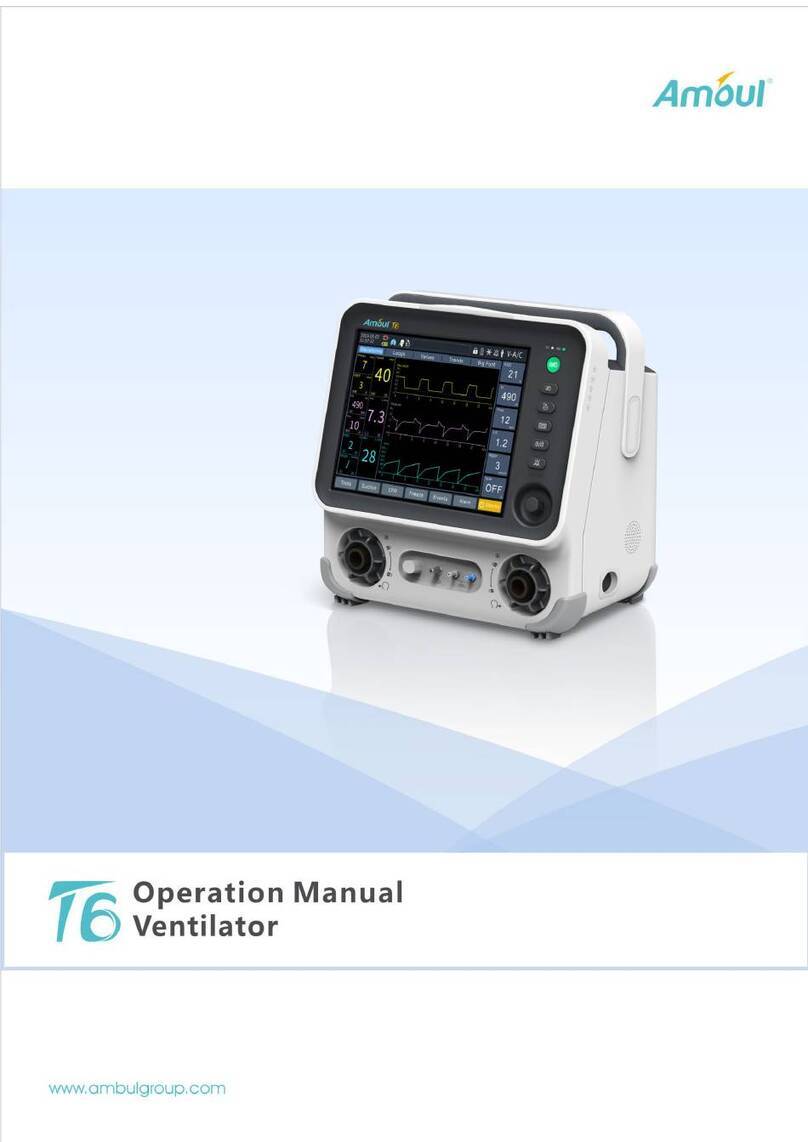
Amoul D-Tiger AII6000A User manual

密级: ★ABMOBAN0001(A1.0)
I
文件类型
文档
项目编号
601
文件编号
H-1.601.00024
打印要求
彩色 □黑白
AII6000A USER MANUAL
参考资料
文件编号
说明
修订记录
版本
ECR/PCN
TCN
更改内容
制订
批准日期
A3.0
ECR20180
108
更新地址、电话传真号码
苑振家
发放部门
□生产部 采购部 □质量部 □市场部 研发部
存档方式
电子文档 纸文档 □其它:
制订
审核
批准
日期
日期
日期
2018.1.18
2018.1.18
2018.1.18

D-Tiger
AII6000A USER MANUAL
Instructions and Safety Considerations of Ambulanc Emergency Ventilator
FILE NO.: H-1.601.00024
VERSION: A3.0
ISSUE DATE: 2018-1-18

H-1.601.00024-A3.0
I
© COPYRIGHT AMBULANC (SHENZHEN) TECH.CO. ,LTD.
2017 ALL RIGHTS RESERVED
Intellectual Property Statement
AMBULANC (SHENZHEN) TECH.CO., LTD. (hereinafter called Ambulanc) owns the
intellectual property rights to this Ambulanc product and this manual. This manual
may refer to information protected by copyrights or patents and does not convey any
license under the patent rights of Ambulanc, nor the rights of others.
Ambulanc intends to maintain the contents of this manual as confidential information.
Disclosure of the information in this manual in any manner whatsoever without the
written permission of Ambulanc is strictly forbidden.
Release, amendment, reproduction, distribution, rental, adaption and translation of
this manual in any manner whatsoever without the written permission of Ambulanc is
strictly forbidden.
are the registered trademarks or trademarks owned by Ambulanc
in China and other countries. All other trademarks that appear in this manual are used
only for editorial purposes without the intention of improperly using them. They are the
property of their respective owners.
Responsibility Statement on the Manufacturer Party
Contents of this manual are subject to changes without prior notice.
All information contained in this manual is believed to be correct. Ambulanc shall not
be liable for errors contained herein nor for incidental or consequential damages in
connection with the furnishing, performance, or use of this manual.
Ambulanc is responsible for the effects on safety, reliability and performance of this
product, only if:
all installation operations, expansions, changes, modifications and repairs of this
product are conducted by Ambulanc authorized personnel;
the electrical installation of the relevant room complies with the applicable
national and local requirements;
the product is used in accordance with the instructions for use.
Warning
This equipment must be operated by skilled/trained clinical professionals.
It is important for the hospital or organization that employs this equipment to carry
out a reasonable service/maintenance plan. Neglect of this may result in machine
breakdown or personal injury.

H-1.601.00024-A3.0
II
Warranty
THIS WARRANTY IS EXCLUSIVE AND IS IN LIEU OF ALL OTHER WARRANTIES,
EXPRESSED OR IMPLIED, INCLUDING WARRANTIES OF MERCHANTABILITY
OR FITNESS FOR ANY PARTICULAR PURPOSE.
Exemptions
Ambulanc's obligation or liability under this warranty does not include any
transportation or irresistible natural disaster or other charges or liability for direct,
indirect or consequential damages or delay resulting from the improper use or
application of the product or the use of parts or accessories not approved by
Ambulanc or repairs by people other than Ambulanc authorized personnel.
This warranty shall not extend to
Malfunction or damage caused by improper use or man-made failure.
Malfunction or damage caused by unstable or out-of-range power input.
Malfunction or damage caused by force majeure such as fire and earthquake.
Malfunction or damage caused by improper operation or repair by unqualified or
unauthorized service people.
Malfunction of the instrument or part whose serial number is not legible enough.
Others not caused by instrument or part itself.
Safety Information
Danger
Indicates an imminent hazard that, if not avoided, will result in death or
serious injury.
Warning
Indicates a potential hazard or unsafe practice that, if not avoided, could
result in death or serious injury.
Caution
Indicates a potential hazard or unsafe practice that, if not avoided, could result
in minor personal injury or product/property damage.
Note
Provides application tips or other useful information to ensure that you get
the most from your product.

H-1.601.00024-A3.0
III
Product information
Product Name: D-Tiger TM Emergency Ventilator
Mode: AII6000A
Manufacturer: Ambulanc (Shenzhen) Tech. Co. , Ltd
Manufacturer address:3rd Floor, Block C, Building #5, Skyworth Innovation Industry
Park, Tang Tou 1st Road, Shiyan Town, Baoan District, 518108 Shenzhen,China
Warning
This device is not intended for home using!
Company Contact
Manufacturer: Ambulanc (shenzhen) Tech.Co., Ltd.
Address: 3rd Floor, Block C, Building #5, Skyworth Innovation Industry Park, Tang
Tou 1st Road, Shiyan Town, Baoan District, 518108 Shenzhen,China
Tel: +86-755-26072210
Fax: +86-755- 23016012
Website: http://www.ambulgroup.com
E-mail: manager@ambu-lanc.com
EC-Representative: Shanghai International Holding Corp. GmbH(Europe)
Eiffestrasse 80,20537 Hamburg,Germany
Contact Pers.: Qiming Cheng
Telephone: +49-40-2513175
Fax: +49-40-255726
Preface
Manual Purpose
This manual contains the instructions necessary to operate the product safely and in
accordance with its function and intended use. Observance of this manual is a
prerequisite for proper product performance and correct operation and ensures
patient and operator safety.
This manual is based on the maximum configuration and therefore some contents
may not apply to your product. If you have any question, please contact us.
This manual is an integral part of the product. It should always be kept close to the
equipment so that it can be obtained conveniently when needed.
Intended Audience
This manual is geared for clinical professionals who are expected to have a working
knowledge of medical procedures, practices and terminology as required for
emergency rescue.
Illustrations
All illustrations in this manual serve as examples only. They may not necessarily
reflect the setup or data displayed on your ventilator.

H-1.601.00024-A3.0
IV
Contents
1. The Basics ..................................................................................................................................1
2. Description..................................................................................................................................3
2.1 Uses.....................................................................................................................................3
2.2 Ventilation function ............................................................................................................3
2.3 Demand flow function.........................................................................................................4
2.4 Patient valve........................................................................................................................4
2.5 Audio response....................................................................................................................5
3. Safety instructions......................................................................................................................6
3.1 Safety regulations................................................................................................................6
4. Installation.................................................................................................................................10
4.1 Connecting the oxygen cylinder........................................................................................10
4.2 Ventilation hose ................................................................................................................11
4.3 Wall mounting set.............................................................................................................12
4.4 Please check as below advised carefully before using............................................13
5. Using the ventilator..................................................................................................................14
5.1 Switching on / self test......................................................................................................14
5.2 Selecting the ventilation settings.......................................................................................14
5.3 Performing ventilation ......................................................................................................15
5.4 Monitoring ventilation ......................................................................................................16
5.5 Demand Flow....................................................................................................................16
5.6 Terminating ventilation or Demand Flow.........................................................................17
5.7 Alarm signals ....................................................................................................................17
5.8 Audio response for user guidance.....................................................................................20
5.9 Calculation of oxygen content/remaining operating time.................................................22
5.10 Alternative ventilation procedures..................................................................................23
6. Hygienic preparation................................................................................................................24
6.1 AII6000A..........................................................................................................................24
6.2 Patient valve......................................................................................................................24
6.3 Ventilation hose ................................................................................................................24
6.4 Masks................................................................................................................................25
6.5 Fittings ..............................................................................................................................25
6.6 Cleaning and disinfection procedure.................................................................................25
7. Functional checks....................................................................................................................27
7.1 Intervals.............................................................................................................................27
7.2 Checking for leaks in the system.......................................................................................28
7.3 Checking the patient valve................................................................................................28
7.4 Checking the alarm systems..............................................................................................29
8. Troubleshooting........................................................................................................................31
9. Servicing....................................................................................................................................33
9.1 Intervals.............................................................................................................................33
9.2 Performing technical safety check and servicing..............................................................33
9.3 Battery...............................................................................................................................34
9.4 Change valve membrane in patient valve..........................................................................35
9.5 Storage ..............................................................................................................................35
9.6 Disposal.............................................................................................................................35
10. Product and accessories......................................................................................................36
10.1 Standard product.............................................................................................................36
10.2 Optional Accessories.......................................................................................................36
10.3 Consumables...................................................................................................................36
11. Technical data.........................................................................................................................37
11.1 Specifications..................................................................................................................37
11.2Product structure diagram................................................................................................38
11.3 Relationship between ventilation parameters..................................................................39
12. Warranty..................................................................................................................................40
13. Storage and transportation...................................................................................................41

H-1.601.00024-A3.0
V
14.EMC declaration......................................................................................................................42
14.1 Guidance and manufacturer’s declaration – electromagnetic emission –for all
EQUIPMENT and SYSTEMS................................................................................................42
14.2Guidance and manufacturer's declaration –electromagnetic immunity –for all
EQUIPMENT and SYSTEMS................................................................................................43
14.3 Guidance and manufacturer’s declaration – electromagnetic immunity.........................44
14.4 Recommended separation distances between portable and mobile RF communications
equipment and the EQUIPMENT or SYSTEM......................................................................46

H-1.601.00024-A3.0
1–46
1. The Basics
A: AII6000A control panel
1 Mask/tube ventilation switch with indicator LEDs.
2 Ventilation pressure gauge.
3 Alarm panel.
4 Alarm mute button.
5 Respiratory stalls
6 Regulator knob, ventilation parameters
7 Stop notch
8 LED Demand flow
9 ON/OFF switch
B: AII6000A connections
10 Pressurized gas connection
11 Product label
12 Battery compartment
13 Speakers
14 Pressure gauge hose connection
15 Fresh air intakes
16 Outlets
C: AII6000A device combinations
17 Masks
18 Patient valves
19 Pressure pipeline
20 Ventilation hose
Symbol
Meaning
Emergency ventilation mode —Toddler
Emergency ventilation mode —Child
Emergency ventilation mode —Adult
IPPV warning mode —Please be cautious when the
knob going over this symbol during usage

H-1.601.00024-A3.0
2–46
13
12
17
19
20
18
2
1
4
6
7
8
9
3
5
10
16
14
15
11

H-1.601.00024-A3.0
3–46
2. Description
2.1 Uses
AII6000A is an automatic oxygen respiration device (short-term ventilator) with
additional inhalation facility.
You can use AII6000A:
To revive patients at the site of the emergency;
For longer periods in more protracted emergencies, e.g. fires;
For short-term O2 inhalation using a respiration masks.
You can use AII6000A while transporting patients:
Between the various rooms and departments of a hospital;
Between the hospital and other premises;
In emergencies;
When transport over considerable distances is planned.
AII6000A:
Is designed to provide controlled ventilation to persons of 10kg body weight
or more;
Is used to treat respiratory arrest;
Can be preset to parameters that ensure evenly balanced ventilation,
provided that the selected Maximum ventilation pressure Pmax is not
exceeded.
Permits respiration-controlled oxygen inhalation in Demand mode.
2.2 Ventilation function
AII6000A operates within a pressure range of 2.7 to 6 bar and at a flow rate of not less
than 70l/min O2. It has a built-in power pack.
It uses high-pressure, medicinal-grade oxygen. An external pressure reducer brings
this down to the required operating pressure. The oxygen supply is fed in at input
valve 10.
The ventilation settings are continuously variable. These settings (frequency and
volume per minute are coupled) and the inspiration/expiration ratio of 1:1.67 are
regulated by internal electronic control mechanisms.
The gas for inspiration flows along the hose and through the patient valve and either
the mask or tube into the patient’s airways. The patient valve is fitted with a one-way
valve membrane that enables expired gas to be conducted away through the outlet.
You can check the course of ventilation at ventilation pressure gauge 2.

H-1.601.00024-A3.0
4–46
2.3 Demand flow function
The Demand flow setting switches the AII6000A breathing-controlled O2 inhalation.
Such inhalation must be carried out with the respiration mask. A small inspiration
(trigger) pulse causes oxygen to continue flowing until slight overpressure interrupts
the flow. Expiration then takes place via the patient valve as in ventilation.
2.4 Patient valve
The gas for inspiration is channeled into the patient's airways through the patient
valve.
The valve is designed to enable spontaneous breathing in the event of failure of the
AII6000A.
When connecting the patient valve, take care to ensure that the direction of
respiratory gas flow is correct (see arrow).
1
Outlet
Φ30mm Convex cone Interface
2
Intake
Φ15mm/20mm Coaxial Interface
3
Patients connector (Connect to mask
/ intubations)
Φ15mm/20mm Coaxial Interface
4
Emergency air intake
Non-standard interfaces
5
Pressure measurement port
Φ5mm Non-standard cylindrical interfaces

H-1.601.00024-A3.0
5–46
2.5 Audio response
The device has an audio response facility that can be switched on for user guidance,
especially for users who have little practice.
If audio response is not required, a key combination can be used to switch it off
(See “5.8 Audio responses for user guidance”).

H-1.601.00024-A3.0
6–46
3. Safety instructions
3.1 Safety regulations
For your own safety and that of your patients, please observe the following
points:
General
Please read the directions for use carefully. They are an integral part of the
ventilator and must be kept available for reference at all times.
Continuing long time supply high concentrated oxygen will cause toxic
effects, patients afford time are varied on different ages and self conditions.
AII6000A is a device driving by internal battery power.
Working conditions:
Ambient temperature: 0℃~ +40℃
Air humidity: Relative humidity less than 95%.
Atmospheric pressure: 70kPa ~ 110kPa.
Use the AII6000A for the described purpose only (See “2.1 Uses”).
Warning:
Do not use the AII6000A in toxic environments or where there is a risk of
explosion.
AII6000A is not suitable for hyperbaric use (pressure chamber).
Do not use AII6000A with flammable anesthetics.
A back-up ventilator should always be available in case of technical failure.
Before starting to work with AII6000A, you must understand how to operate
it.
To prevent infection or bacterial contamination, please observe section “6.
Hygienic preparation”.
AII6000A should be used only by medically qualified personnel who have
had training in ventilation techniques. Incorrect use can cause severe
physical injury.
This Equipment should be stored at ambient temperature -40 ℃~+ 50℃,
relative humidity less than 95%, and no corrosive gases and well-ventilated
room.
Only trained medical staff can operate this ventilator.

H-1.601.00024-A3.0
7–46
Can cause explosive reactions when high-pressure oxygen and
combustible material( grease, oil,alcohol, etc.) meet.
This equipment is only suitable for patients weight more than 10KG.
NOTE:
Please note that a safe distance must be maintained between AII6000A
and equipment that emits HF radiation (e.g. mobile phones), otherwise
malfunctions may occur.
We recommend that maintenance work such as inspections and repairs be
performed only by the manufacturer: Ambulanc, or by qualified technicians
expressly authorized by Ambulanc.
Malfunctions and a lack of biocompatibility may result if third-party articles
are used. Please note that in such cases all warranty entitlement and
liability claims shall be void where items other than the accessories
recommended in the instructions for use or original spare parts are used.
Oxygen
Warning:
Spontaneous explosive reactions can occur if high-pressure oxygen comes
into contact with flammable substances (fat, oil, alcohol etc.):
Keep the equipment and all screw connections absolutely free from oil and
grease.
Always wash your hands before starting to work on the oxygen supply.
Smoking and open flames are strictly prohibited in the vicinity of all fittings
containing or transporting oxygen.
During assembly and when changing the oxygen cylinder, only hand
pressure should be used when tightening the screw connections to the
cylinder and to the pressure reducer. Never use tools for this purpose.
Excessive tightening damages the screw threads and seals, and can
cause leaks.
Protect oxygen cylinders from accidental falls. If a cylinder falls over, the
pressure reducer or the valve may break off and cause a violent explosion.
Warning:
Always open the valve of the oxygen cylinder slowly to prevent pressure
damage to the other fittings.
The oxygen cylinder should never be completely emptied, as this may
allow air containing moisture to enter the cylinder and cause corrosion.

H-1.601.00024-A3.0
8–46
Ventilation/Operation
Caution:
Both patient and ventilator must be kept under constant observation during
ventilation.
Make sure that neither the outlet nor the emergency air intake on the
patient valve are blocked or their function impeded in any other way, e.g.
by the patient’s position.
Software:
Extensive validation tests have been performed to minimize risks arising
from software errors.
Accessories:
Please protect the silicone and rubber components from UV radiation and
prolonged exposure to direct sunlight, as this can make them brittle and
friable.
Adjustable knob:
The effective adjustable area of the knob is situated in the colorized scale
of operation panel only (the yellow, orange, brown, green and white area
on above figure), and other region is strictly forbidden to access.
Warning:
It is strictly forbidden turning the knob into non-operating area which is
indicated by the red line and arrow in the illustration above with brute force,
it will disturb the preset output parameters, and may cause damage to the
device.
Before starting the device, please rotate the knob counterclockwise softly,
when it encounter an obvious resistance, stop rotating and check whether

H-1.601.00024-A3.0
9–46
the indicating on the knob is aligned with the lower left edge of yellow
colorized scale. If not, the device may exist problem, please stop using and
contact the manufacturer or the Ambulanc authorized personnel.

H-1.601.00024-A3.0
10–46
4. Installation
A permanent mounting is usually necessary only when AII6000A is installed as a
fixture in rescue vehicles, helicopters or aircraft .If AII6000A is supplied complete on a
carrying platform or in an emergency rucksack, it is ready for use and requires no
further installation. Separate directions for use are supplied for carrying platforms and
emergency rucksacks.
Caution:
In order to ensure safe and reliable operation, functional tests must be carried
out after installation (see “7. Functional checks”).
4.1 Connecting the oxygen cylinder
Caution:
Always wash your hands thoroughly before starting any work on the oxygen
supply. Products containing hydrocarbons (e.g. oils, greases, alcohols, hand
creams, sticking plasters) may cause explosive reactions if they come into
contact with high-pressure oxygen.
Never use wrenches or similar tools to tighten or loosen the screw
connections.
Removing the empty cylinder
Close the valve of the oxygen cylinder. Switch on AII6000A with ON/OFF
switch 9. This exhausts any residual oxygen and depressurizes the
ventilator. Wait until the pressure gauge on the pressure reducer shows an
oxygen content of zero before undoing the screw connection by hand.
Switch off AII6000A with ON/OFF switch 9.
Then loosen the screw of reducing valve connected to the cylinder.
Connecting the new cylinder
1. First briefly open and close the valve of the new oxygen cylinder. This
should blow out any particulate matter.
Caution:
Keep the valve opening away from the body, making sure that neither
yourself nor other persons can be injured by escaping particles.
2. Next use the fluted connecting nut to couple the pressure reducer to the
valve on the oxygen cylinder. Tighten the connecting nut by hand.

H-1.601.00024-A3.0
11–46
3. If the pressure hose is not already connected to the exit from the pressure
reducer, make this connection with the 9/16’’-18UNF connecting nut.
4. Screw the other end of the pressure hose on to pressurized gas connection
10 on the AII6000Aif this has not yet been done.
4.2 Ventilation hose
1. Slide the pressure gauge hose onto connection 14.
2. Slide the ventilation hose onto connection 15. Make sure that this does not
cause any kinks in the pressure gauge hose already connected. If necessary,
turn the ventilation hose while sliding on as appropriate.
Caution:
Always grasp the ventilation hose and pressure gauge hose by their end only
(position of arrow in adjacent drawing), otherwise they may be damaged or
split.

H-1.601.00024-A3.0
12–46
3. Connect the patient valve to the other end of the ventilation hose and
pressure gauge hose.
4. If a mask is being used for ventilation, attach the mask connection to the
patient valve (identical with hose connection), or if the patient is intubated,
attach the patient valve to the hose.
Warning:
Please use the ventilation hose which is supplied by the manufacturer
Ambulanc, otherwise Ambulanc is not responsible for any adverse effect on the
product performance.
If you are using the disposable patient ventilation hose, please discard it after
using.
4.3 Wall mounting set
A wall mounting set is available for permanent fixing, e.g. on a vertical surface
inside a vehicle.
Please refer to the sheet enclosed with the wall mounting set for details of
dimensions and installation procedure.

H-1.601.00024-A3.0
13–46
4.4 Please check as below advised carefully before
using
Check power alarm status.
Check Respiratory Valve for patients.
Check trigger pressure.
Check the stenosis alarm.(see “7.4 Checking the alarm systems”)
Check the disconnection alarm. (see “7.4 Checking the alarm systems”)
Check the drop in O2 pressure alarm. (see “7.4 Checking the alarm systems”)
Table of contents
Other Amoul Fan manuals
Popular Fan manuals by other brands

Euromatic
Euromatic TF4603TR-S instruction manual

WAC Lighting
WAC Lighting Mocha XL F-064 installation instructions

Patron
Patron AS-550 owner's manual

Monte Carlo Fan Company
Monte Carlo Fan Company 5HS42XX Series owner's guide

Sunbeam
Sunbeam FA7200 Instruction booklet

Emerson
Emerson SWEEP ECO Wi-Fi owner's manual

Vent-Axia
Vent-Axia 45 90 49 installation instructions

Hunter
Hunter 42823-01 owner's guide

Fanimation
Fanimation STELLAR MAD7997 Series manual

Brillian
Brillian LAGUNA ABS installation manual

Tecnogas
Tecnogas FastPipe Installation Manual and Declaration of Warranty

Oxygen 8
Oxygen 8 SERENA Installation & operation manual