AMP AMP 21x-2 User manual

AMP mounting and user manual, Pumps 2022-1 page 1 of 14
AMP - User manual for
70 bar aqua misting pump system for cooling and humidifying
This unique type plate is placed both inside the cabinet and on the head frame.

AMP mounting and user manual, Pumps 2022-1 page 2 of 14
1.0 MODEL INFO
Item nr. AMP 21x-2
2,2 kW, 540 l/h
AMP 22x-2
2,2 kW, 1200 l/h
AMP 42x-2
4 kW, 1200 l/h
AMP 43x-2
4 kW, 1800 l/h
Max. pressure [bar]
70
70 70
70
Water flow max [l/h|l/min)
1:1
-
540 (9)
1:1,5 - 800 (13,3) 1:1 - 1200 (20)
1:1,2
-
1500 (25)
Different
speed
1:1 - 1:1,5 - 1:2 - 1:3
1,5 - 1:2 - 1:3 1:1 - 1:1,2 1:1,2 - 1:1,5 - 1:2 - 1:3
Different capacity [l/h]
540|360|270|180
800|600|400 1200|1000
1500
|1200|900|600
Voltage [Vac]
3 x 400
3 x 400 3 x 400
3 x 400
Current [Amp]
4,5
4,5 7,95
7,95
Oil type
SAE 15/40
SAE 15/40 SAE 15/40
SAE 15/40
Standard filter type
10”
–
5 My
10” – 5 My 20” – 5 My
20”
–
5 My
Dimension wall
-
T [cm]
W70xH90xD42
W70xH90xD42 W70xH120xD42
W70xH120xD46
Dimension wall
-
W [cm]
W65xH90xD42
W65xH90xD42 W60xH120xD42
W60xH120xD46
Weight (all incl. approx.)
51 kg
55 kg 65 kg
72 kg
Dimension shipment
80x60xH5
5 [cm]
80x60xH55 [cm] 80x60xH55 [cm]
80x60xH5
5 [cm]
Noise level (approx.)
70
-
75 dB(A)
70-75 dB(A) 75-80 dB(A)
75
-
80 dB(A)
This user manual applies to various models and combinations:
If you buy a pump system with tank solution or other simple systems a lot of the info inside this
manual will not apply to you.
If you buy a solution without cabinet and without motor protection, you will not need the electrical
info inside this manual.
VERY IMPORTANT: Motor protection and all other electrical wiring must be installed in
accordance with local electrical law.
If your purchase includes a SAFE misting controller, you will find a separate instruction for this
controller.
For more information about AMP product series, contact: sales@amn-misting.com

AMP mounting and user manual, Pumps 2022-1 page 3 of 14
2.0 SAFETY INSTRUCTIONS AND WARNINGS
Before installing your new aqua misting pump, please read the following instructions carefully to
avoid damages to the user, surroundings, and the pump system itself.
2.1 BEFORE OPERATING THE PUMP SYSTEM
Before operating the pump system, carefully inspect the shipment to locate possible missing parts or
damages. Please report anything, which is not satisfying, to the supplier of this system.
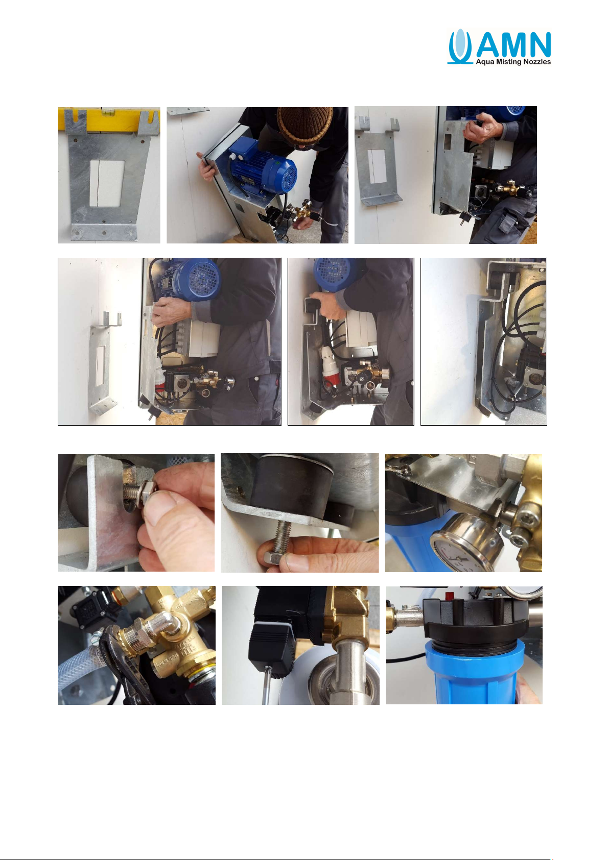
The plug on top of the high-pressure pump must be replaced with the enclosed oil dip stick.
Oil level must be checked.
The insulation on the wire must be flawless, and without cracks. In doubt, please contact the
supplier of this system.
Please see if the voltage displayed on the registration plate on the motor is equal to the voltage in
your power supply.
2.2 CURRENT CONNECTION
Wrong current connection of the pump system can lead to life threatening electrical chocks. The
pump system must only be connected to electrical circuits with earth leak circuit breaker.
2.3 SAFETY INSTRUCTIONS
This pump system can produce a high pressure. Wrong handling can lead to serious injuries.
For your own sake and safety of other persons please follow the rules listed below:
The pump system must not be operated if cable or safety devices are damaged.
The pump system may only be used for humidifying of air – it may not be used as a high-pressure
cleaner.
Water pressure from the pump system should never be pointed at people, animals etc.
2.4 SAFETY DEVICES ON THE PUMP SYSTEM
The high-pressure pump is on the pressure side equipped with a bypass valve. This valve leads the
water, which is not needed on the high-pressure site, back to the suction side of the filter. Do not
mount a ball valve or similar, which can shut off waterflow between the pump system and nozzles +
from the pump system and back to the filter section.
The pump unit will be over heated if more than 80 % (Capacity of the pump) is running in
circulation, which may cause breaking the pump, valves, nozzles etc. The temperature may not
exceed 50 °C.
2.5 MOTOR OVERLOAD PROTECTION
The motor is fitted with a motor protection relay which protects the motor against overload. At an
increased power consumption (error) the motor protection relay will automatically turn off the
power supply and the motor are switched off. Before rebooting the pump system at the red button
(inside the cabinet), the cause of failure must be found and repaired.
Be aware that the motor is not overheated if it has too many start/stops.
2.6 MOTOR CONNECTION TO POWER
All systems have CEE plug 400 Vac pre-installed. In case of pump service, the CEE plug must be
removed from socket to avoid any hazard.

AMP mounting and user manual, Pumps 2022-1 page 4 of 14
3.0 OPERATION DIRECTIONS
3.1 WATER CONNECTION
Water connection to the pump uses a regular water hose minimum 3/4” in diameter and minimum
1,5 bar pressure (The pump itself just need more than 0 bar). The water is lead into the pump
through low pressure filters. Flow direction is indicated by an arrow on the filter housing. Please
check the filters for impurities by routine. Filter house is delivered with a standard 5µm cartridge
filter inside.
3.2 START/STOP PROCEDURE
Start
Observe that the stop button on the electrical box is set to “OFF” to assure it is turned off.
Turn on the water supply and turn the power switch to “MAN”. Your system will now be filled with
water. Now the pump system is ready for manual or automatic operation.
Stop
Stop the pump system by turning the power switch to “OFF” and pump system will stop
immediately.
3.3 PRESSURE REGULATION
The pump has a pressure regulation. Factory settings are max. 70 bar. This basic adjustment must
not be changed. Pressure regulation is automatic with different numbers of nozzles.
3.4 FUNCTION
The pump system is provided with a manual and an automatic mode.
MAN:
Used when the pump system must run continuously (manual), such as soaking etc.
In the manual position, there is no security system for pressure, bleed-off etc.
OFF: Pump system is turned off.
AUTO:
Used when the pump system must run automatically (normal position). Can start the pump system
by external thermostat, timer, or other control systems. If the pump system does not reach operating
pressure within a given period of 20 sec., it will turn off. Before re-starting the pump system, the
cause of failure must be found. This function is controlled by a 25-bar pressure switch.
To restart – turn off the switch and return to “AUTO” mode again.
V-belt drive:
After few hours of operation, make a control, that the operation in total is OK including an extra
control, that the pulley is tensioned and in the right position.
Inside the belt house, you find an extra V-belt – for service if needed.

AMP mounting and user manual, Pumps 2022-1 page 5 of 14
4.0 MAINTENANCE
Your pump demands just a minimum of maintenance, however before operation the oil level must
be checked.
Pump routine maintenance:
After the first 50 hours: Oil change. (Oil type 15W-40).
Every 500 hours: Oil change (minimum each year).
Every 1000 hours: Replace the valves – Replace piston seal rings (or replace a service pump).
Bad seal rings, condense or cleaning with water can eventually lead to water in the oil.
In extreme conditions/use – Please check/replace oil etc. regularly.
If you have too much water leak, you can replace the entire pump unit with a service pump.
Filters:
The water filters must be checked and changed regularly. Minimum once a year.
Check pressure before and after the filter. If pressure loss exceeds 1 bar, the filter must be changed.
Pre-cleaning:
Before connecting the water supply hose and the high-pressure hose/pipe: Pipe system and
couplings should be cleaned for dust and sand (no particles inside pipes).
To empty the pump for water:
Disconnect the hose/pipe before and after the pump and demount filter house.
Start the pump system “MAN”. Let the motor run for approx. 30 sec. until the pump system is
totally empty for water.
Dry out fittings and other parts with e.g., high-pressure air to ensure all parts are completely dry.
The pump system should be mounted in a place free of frost and if not possible, you need to protect
the pump system with an anti-freeze fluid.
If the pump system by mistake is frozen, do NOT start. De-freeze pump system and accessories
before start-up.
NEVER START A FROZEN PUMP SYSTEM!
Pump for multiple sections service – pipeline with high pressure:
Before you make service on the decentralized solenoid valve or when the system is stopped over a
long period as the winter-season.
Make a pressure relief by opening the valve at the end of the pipeline or loosening a screw fitting on
the pipeline for taking of the high pressure.

AMP mounting and user manual, Pumps 2022-1 page 6 of 14
5.0 TROUBLESHOOTING AND SOLUTIONS
Error
Possible cause
Correction
The pump system
will not start
Blown fuse.
No power supply.
Change fuse
Connect power.
The pump system
stops shortly after
start-up
Wrong current connection.
Water pressure cannot be
reached.
Check power supply matches type plate.
Check if your water supply can provide
sufficient water flow. Water supply more than
0 bar (specification 1,5 bar).
High pressure more than 40 bar.
Pressure is
unstable and
bumping
Water supply is insufficient
or clogged.
Water inlet filter is clogged.
Impurities in valves or
broken valves.
Check water supply.
Filters must be checked or changed.
Clean or change valves.
No working
pressure
No water inlet.
System is frozen.
Broken valves.
Pipe system leaking.
Check water inlet connection / filters.
De-freeze.
Change valves.
Repair pipe systems.
Pump unit loses
water
Leaking gaskets Check and repair gaskets.
Replace
the
pump

AMP mounting and user manual, Pumps 2022-1 page 7 of 14
Quick guide for use of AMP Pumps 2022-1.
Filter change:
Change - Max 500 hour or 1 year
or pressure difference > 1 bar
Oil service:
Mineral oil SAE 15W-40:
Change every max. 500 hours or 1
year
bad seal rings, condense or cleaning with water can
eventually lead to water in the oil
.
Easy access:
Twist the cabinet out to make oil
change and easy service access.
Accumulator control:
1 bar pressure accumulator must be
controlled every max. 500 hours or
once every year.
Control of the V-belt:
Push with 1 kg pressure on center of
V-belt through inspection hole - and
the belt should move from 4 to 6
mm. If more than 6 mm, you need to
tighten.
Control every max. 500 hour or 1
year
Extra V
-
belt enclosed with pump system purchase
.
Electrical fault:
Motor thermal relay will stop power
supply in case of circuit fault.
To restart press the red button
Pressure fault:
Switch of to “0” before restart.
“MAN” position is without any
security functions.
Pressure change:
Adjust with wrench
60 bar +/- 10 bar
Gauges:
All gauges must show values outside
the red areas.
This quick guide is also delivered in a laminated version with the pump.

AMP mounting and user manual, Pumps 2022-1 page 8 of 14
Delivery and mounting the pump.
Delivery:
Demounting from transportation pallet:

AMP mounting and user manual, Pumps 2022-1 page 9 of 14
When ordering a universal pump with AMP 54.
When delivered the system is standard for 1 section:
Bleed-off valve for eliminating the pressure when pump stop (No dripping from nozzles)
Low pressure solenoid valve open 1 sec. before pump start (reduced vacuum at start)
Why change the pump to handle multiple sections:
The system will be able to handle capacity down to 0,0 l/h with a temperature safety system.
The pump and low-pressure solenoid valve operate simultaneously.
A non-return valve ensures that water remains in the main pipeline and therefore provides a
better, faster, and more even misting
What you MUST change if you run for multiple sections:
Insert a short wire (jumper) into the terminal 23|24 and the program change to multiple sections
incl. temperature security system.
Insert the non-return valve straight after the pump and you have constant pressure inside the pipe
feeding line for multiple sections.

AMP mounting and user manual, Pumps 2022-1 page 10 of 14
Wall mounting:
Mounting details (close up):

AMP mounting and user manual, Pumps 2022-1 page 11 of 14
Low-pressure water connection and power supply:
CEE plugs are used for simple start-up and
as a main safety “circuit breaker”.
High-pressure connection with Stainless steel pipe (Normal connection):
A = ball valve not allowed
B = Free distance (without pipe hanger)
from pump to pipe > 1 mtr.
C = Free distance to pipe hanger > 0,5 mtr.
High-pressure connection AMP 16 (Extra equipment):
A
B
C
C

AMP mounting and user manual, Pumps 2022-1 page 12 of 14
How to replace a pump (service pump):
View of the replacement pump
Demount the high-pressure pipe. Demount the by-pass hose Demount the high-pressure set.
Demount the filter set The pump is ready for Demount the gauge. Demount the fitting
demounting

AMP mounting and user manual, Pumps 2022-1 page 13 of 14
Demount the 3 nuts below the pump and you
can take out the pump from position.
Make all the steps backwards when replacing the new service pump.
The bolts in the bottom of the pump – if same position and same length of the bolts - the V-belts are
properly tensioned again. Be sure that the V-belt are OK tightened.
Control of the V-belt:
Push with 1 kg pressure on center of V-belt through inspection hole - and the belt should move from
4 to 6 mm. If more than 6 mm, you need to tighten. Adjust the 3 nuts set below of the pump.
Demount the 2
screws
Demount the front guard and remove the pulley
Tighten the screw
In the center hole
Demount the pulley
These nuts must be
kept
in p
osition
Loosen the nut and
demount t
he 3 bolts

AMP mounting and user manual, Pumps 2022-1 page 14 of 14
Frost protection of the pump and pipeline.
If the system should be shut down for the winter, make sure that it is frost protected. It is almost
impossible to drain all the water from the system, so instead, fill it with anti-freeze windshield
washer fluid (Min. approved for -21°C)
You will need about 1 liter of anti-frost fluid per 10 meters of pipe + a some extra for pumps, filters
etc.
AMP 48 remote wi-fi control for service, can with success be used for this job.
1. Empty the filter house and insert a new cartridge filter.
2. Arrange a tank with a higher level than inlet to the pump (It can be a pressure tank or a
separate low-pressure pump)
3. Put the ¾” low pressure hose down in the tank, ready for water to the pump (no air inside
the hose)
4. Make a manual start of the pump, be sure the pump works OK and makes the right pressure
without any disturbing sounds.
5. Open the end of the high-pressure pipe – one by one if more pipelines.
6. Start the pump and stop again when anti-freeze fluid comes out of the end of the pipeline.
Close the end of the pipeline and proceed to the next pipeline and redo the step – when all
pipelines are filled with anti-freeze fluid continue to the next step.
7. Ensure that the end of each pipeline is closed properly
8. Start the pump with normal pressure and let all the nozzles spray minimum 30 sec.
The system is now frost protected.
In the springtime or when you are sure to avoid freezing the system, make the same again, but this
time with normal water directly from the pipeline, instead of anti-frost fluid.
Check the pump and pipeline for errors. Change the oil in the pump (SAE 15/40) and the system is
now ready for a new season.
An example of a pump and container that is useful for this job.
This manual suits for next models
3
Table of contents
Popular Water Pump manuals by other brands

Little Giant
Little Giant 3-MDX Operating instructions and repair parts list

Smartpond
Smartpond 52672 manual

Aqua Medic
Aqua Medic DC Runner 1.2 Operation manual

Pure-Pro
Pure-Pro HF-8367 RO BOOSTER PUMP user manual

Little Giant
Little Giant 5.5-ASPA Series owner's manual

Little Giant
Little Giant EC-400 Series instruction manual