LF Series
Replacement
Seal Kit
Instructions
PUMP ASSEMBLY AND SEAL INSTALLATION
When replacing the seal assembly lubricate all o-rings with food grade
lubricant. Once the pump is assembled turn the stub shaft a few revolu-
tions by hand making sure it turn relatively freely and nothing is rubbing
inside the pump. Running the pump with foreign objects in the pump or
having the impeller making contact with either the cover or the casing
will result in serious damage if not completely destroying the pump.
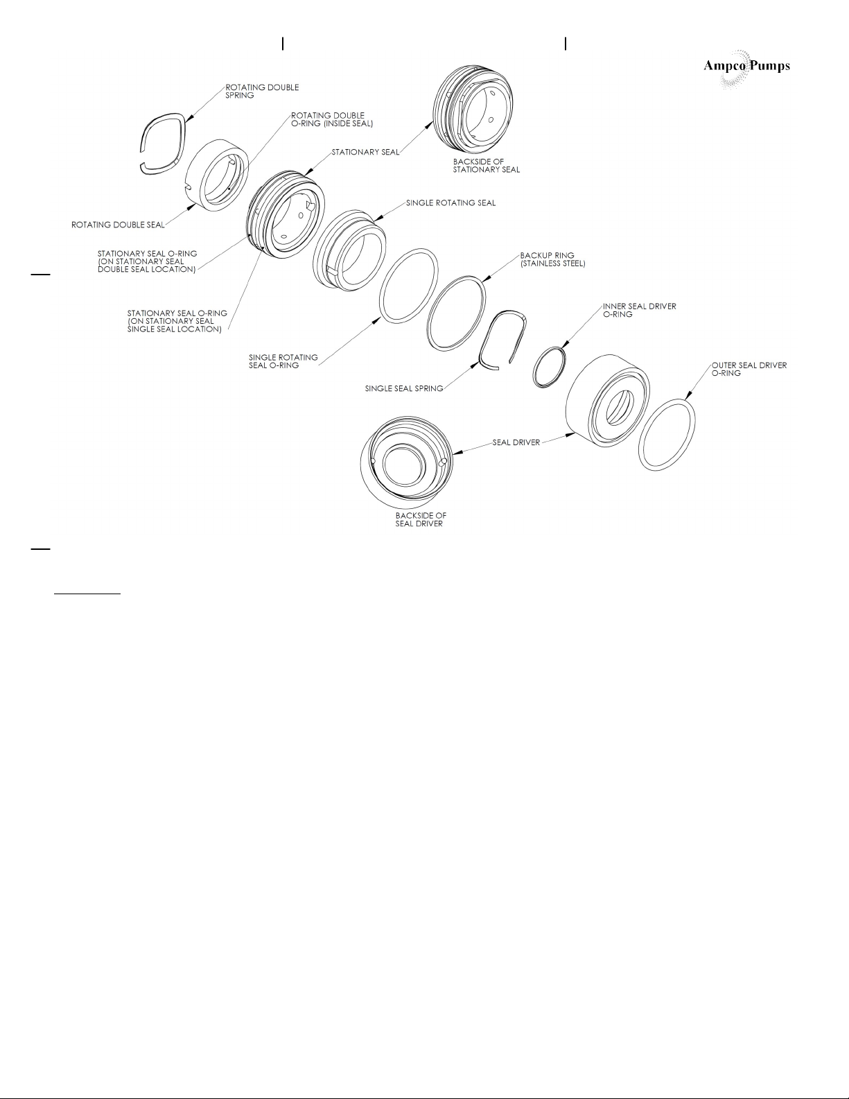
1. For double seals slide the rotating double spring onto the shaft. Use the slot to
set the spring between the driving pins on the shaft and shoulder.
2. For double seals slide the rotating double seal onto the shaft, making sure the
driving pins are in the slots of the rotating double seal.
3. Slide the stationary seal over the shaft and into the casing. Line up a flat on
the stationary seal to the a flat of the window of the casing and gently press the
stationary seal into the casing bore. The stationary seal should be properly seated
before continuing the assembly of the pump.
4. Install inner seal driver o-ring.
5. Assemble the seal driver assembly. Insert the single seal spring into the seal
driver. Insert the backup ring into the seal driver.* Insert the single rotating seal
o-ring into the seal driver. Then insert the single rotating seal into the seal driver
while aligning the notches in the single rotating seal with the pins in the seal
driver.
6. Then slide the rotating seal assembly onto the stub shaft against the stationary
seal. Be sure the outer seal driver o-ring is in the o-ring groove of the seal driver.
7. Insert key into the keyway in the stub shaft.
8. Slide impeller onto the shaft and over the key.
9. Install the impeller nut and impeller nut gasket.* Insert a 3/8” bar into the hole
of the stub shaft to hold the rotating parts while tightening the impeller nut.
Torque the impeller nut to 90 ft-lbs for LF X-pumps and to 40 ft-lbs for all other
LF pumps.
10. Reinstall cover, wing nuts, gasket cover and shaft guard.
NOTE: ONE WAY TO DAMAGE A NEW SEAL IS TO RUN IT DRY BE
SURE THE DOUBLE SEAL FLUSH IS RECONNECTED AND FLOWING
AND THE PUMP IS IN PLACE AND PRIMED BEFORE OPERATING.
*Replacement seal kits come with a backup ring and two different sized impeller
nut gaskets. Use only one backup ring in the seal driver and the impeller nut
gasket that fits the impeller nut for the pump.
REV. TML 3/24/10
SEAL REMOVAL
ATTENTION! BEFORE ATTEMPTING ANY SEVICE ON ANY PUMP OR
MOTOR, DISCONNECT OR LOCKOUT ELECTRICAL POWER TO THE
PUMP MOTOR. IF THE PUMP AND MOTOR ARE TO BE REMOVED AS A
UNIT, NOTE THE WIRING AND CONFIGURATION. USE COLORED OR
NUMBERED TAPE TO MARK THE WIRE CONNECTIONS OF THE PUMP
MOTOR AND POWER SOURCE, FOR RECONNECTION.
TOOLS REQUIRED
7/16” wrench Dead blow hammer
Socket wrench for impeller nut 3/8” round bar
90 degree o-ring pick
1. Disconnect electrical power to the pump motor and follow any lockout / tag-
out procedures in place at your facility.
2. Disconnect pump from the suction piping. Drain all fluids from the pump.
3. Loosen cover nuts. They may need to be tapped loose with a dead blow ham-
mer. Remove cover wing nuts, flat washers (if provided), lock washers (if provid-
ed), cover, cover gasket and shaft guard.
4. Insert a 3/8” bar in the hole in the stub shaft. Turn the impeller nut with a
socket wrench counterclockwise.
5. Remove the impeller nut then the nut gasket.
6. Rotate the impeller so the key is on top.
7. Remove the impeller then the key.
8. Pull out the seal driver assembly. You may have to use a pick to separate the
rotating seal assembly from the stationary seal. The rotating seal, o-ring, spring
and seal driver will come out at as a single component.
9. Push the stationary seal out from the back of the pump using an o-ring pick or
your fingers or both (pushing on opposite sides of the shaft with constant light
pressure the best). Make sure to push outside of the rear seal face to avoid dam-
aging the face for a double seal. Remove stationary seal once pushed out of its’
bore. Check the condition of the casing, rotating seal and stationary seal. Clean
seal and casing and remove any foreign matter before reinstalling the seal.
10. For double seals remove the rotating double seal by sliding the seal off the
shaft remove the rotating double spring as well.
The mechanical seal is the only expandable pump part. It is suggested that
the complete mechanical seal, both stationary and rotating members, be
replaced whenever dripping or leakage occurs at the shaft, or whenever parts
are removed to the point of separating the primary sealing surfaces.


