SPECIFICATIONS
Tape
Width
Reel
Size
Tape
Speed
Playing
Time
Reproduce
Timing
Accuracy
Flutter
and Wow
Starting
Time
Stopping
Time
Fast
Forward
Time
Rewind
Time
Frequency
Response
Signal-to-Noise
Ratio
Record
Inputs
Reproduce
Output
Operating
Controls
VA inch.
7inch,RETMAreel(maximum).
IV2 ips,
lull
track.
IVj ips,halftrack.
3Mips,
full
track.
.3Mips,halftrack.
Full
Track—32
minutes
witii
7 inchreel,
IV2 ips,1200
feet.
Half
Track—64
minutes
with
7 inchreel,
71/2ips,1200
feet.
±0.2%,oran
accuracy
of±3.6
seconds
in
a30-rninuterecording.
71/2ips—Below0.17%rms.
ips—Below0.3%rms.
The
tape
attains
full
speed
in
less
thanone-
fifth
second
ineithertheplayorrecordmode.
Less
thanone
second.
90
seconds
for
full
1200footreel.
90
seconds
for
full
1200footreel.
71/2
ips—40
to
15,000
cps±2db50to
10,000
cps
down
nomorethan4 dbat
15,000
cps.
3M
ips—±2db50to
7500
cps.
Full
Track—over55dbbelow
peak
rec-
ord
level.
Peak
recordlevelisdefinedasthe
point
of3%totalrmsiiarmonicdistortion,
measuredwhileusinga 400cpstone;and
peak
recordlevelincludes
bias,
erase
andre-
produceamplifiernoise.
Half
Track—50
dbbelow
peak
recordlevel.
MICROPHONE:Accommodatesanyhigh
impedancemicrophone,andcanbequickly
convertedfora lowimpedancemicrophone
with
the
plug-in
accessory
transformer(Cat-
alogNo.
17331-1).
LINE:
0.5
volt
requiredfornormalprogram
level.
1.23voltsrmsinto600ohmsatprogramlevel.
PLAY—REC:Theplaymodeis
selected
by
placing
theswitchinPLAYposition.
Therecordmodecanbe
selected
onlybyde-
pressingthe
safety
buttonatthe
same
time
the
selector
switchisplacedinRECposition.
The
safety
button,a flattoppedneonlamp,
remainslightedwhilethemachineisinthe
recordmode.
REWIND—FASTFWD:This
selector
switch
ismechanicallyinterlocked
with
the
PLAY—RECswitch.
1-2
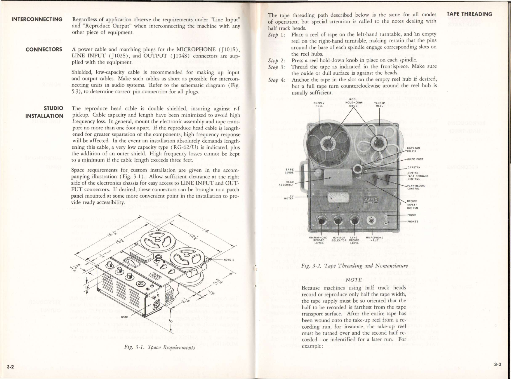
Reproduce
Output
Operating
Controls
Miscellaneous
Monitoring
Head
Assembly
Power
Requirements
Accessories
MIC
RECLEVEL,andLINERECLEVEL
are
separate
mixingcontrols.
TheMONITOR
SELECTOR
switchisused
for
monitoringasdescribedinthe
following
paragraphs;butitfunctions
also
asanoper-
ating
control.InthePLAYmode,the
MON-
ITOR
selector
switchmustbeintheTAPE
position
inordertobringthereproducehead
signaltotheOUTPUT.
A
toggleON—OFFswitch,locatedonthe
control
panel,turnspoweronoroff.When
placedintheONposition,thistoggleswitch
will
cause
the
capstan
torotate;butthe
tape
will
notmove
until
oneofthetwooperating
switchesisturned
from
itsneutralposition.
TheMICROPHONE
input,
a threecircuit
connector,isconvenientlylocatedonthecon-
trol
panel.
ThePHONESoutputisa twocircuit
jack,
locatedonthefrontpanel.
TheLINEINPUT
connector
isa twocircuit
jack
recessed
intothe
right
sideoftheequip-
ment.
TheOUTPUT
connector
isa threecircuit
jack
also
recessed
intothe
right
sideofthe
equipment.
Mating
connectors
aresupplied(see
Table
1-1).
TheMONITOR
SELECTOR
switchallows
monitoring
ofprogram
input,
orreproduce
output.
A phone
jack
andilluminatedv-u
meterareonthefrontpanel.
WhentheTAPEpositionis
selected,
there-
produceoutputcanbemonitored.
WhentheINPUTpositionis
selected,
the
headphones
andmeterreportprogramsignal
level.
Separate
erase,
record,andreproduce
heads
arecontainedina singlehousing.
117volts,50or60cps;0.52ampere,61
watts.
MaintenanceKit:
6392-1
Speed
ConversionKitsto:
3M
ips,60cps
7556-0
71/2ips,60cps
7556-1
3%ips,50cps
7556-2
71/2ips,50cps
7556-3
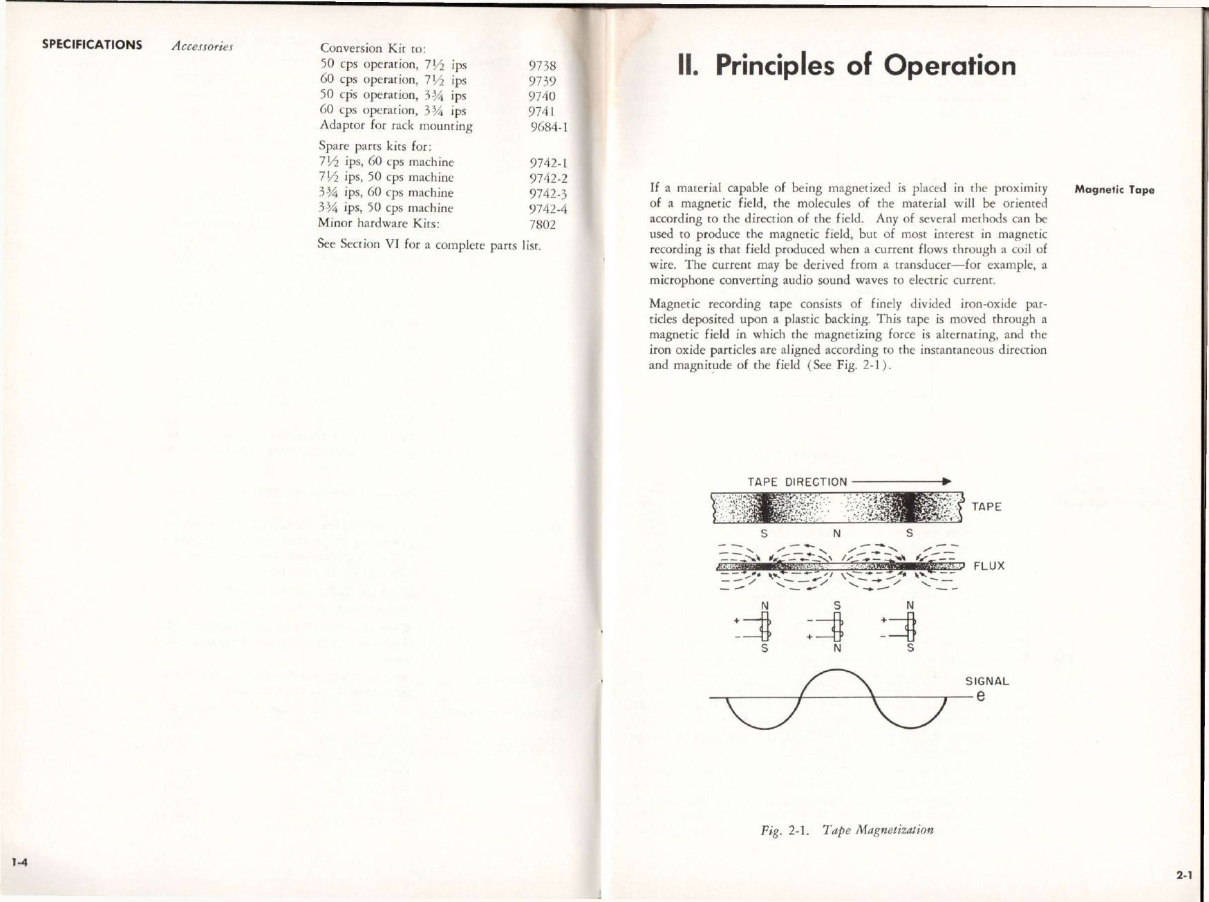
SPECIFICATIONS
1-3