e
For
a
Blank
of
More
Than
4
Seconds
During
recording,
keep
the
REC
MUTE
button
pressed
for
a
longer
blank
section.
Release
the
button
to
enter
the
record-
pause
mode.
eFor
a
Blank
of
Less
Than
4
Seconds
After
pressing
the
REC
MUTE
button
during
recording,
press
the
PAUSE
button
before
the
4-second
interval
has
expired,
to
cancel
the
muting
mode
and
engage
the
record-pause
mode.
To
restart
record-
ing,
press
the
PAUSE
button.
Or
press
the
REC
MUTE
button
again
to
resume
recording
without
stopping
the
tape.
Erasing
Previously
recorded
tapes
will
be
erased
automatically
when
you
make
a
new
record-
ing
on
them.
Alternatively,
tape
can
be
erased
by
“recording”
on
them
with
the
REC
LEVEL
control
set
to
“0”.
Calibration
Procedure
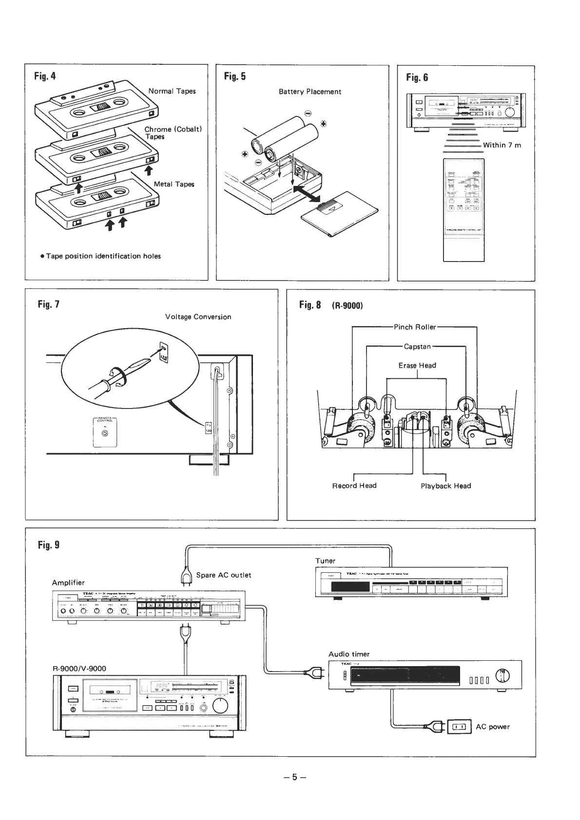
Tapes
with
various
formulas
are
available
from
different
manufacturers.
in
some
cases,
however,
even
when
tapes
are
of
the
same
type,
they
may
differ
depending
on
the
brand
or
sot.
The
calibration
controls
allow
you
to
adjust
the
recording
level
and
bias
for
the
optimum
performance
of
any
tape.
1.
Load
the
tape
on
which
you
want
to
record.
2.
Press
the
PAUSE
button,
then
press
the
RECORD
button.
(On
the
R-9000,
if
the
reverse
play
button
<¢
is
pressed
together
with
the
RECORD
button,
calibration
is
impossible.)
3.
Press
the
CAL
ON
button.
The
record-
ing
of
the
internally
generated
calibra-
tion
signal
starts,
and
the
indicators
light.
4.
Press
the
»
button.
The
direction
indicator
lights
and
the
tape
starts.
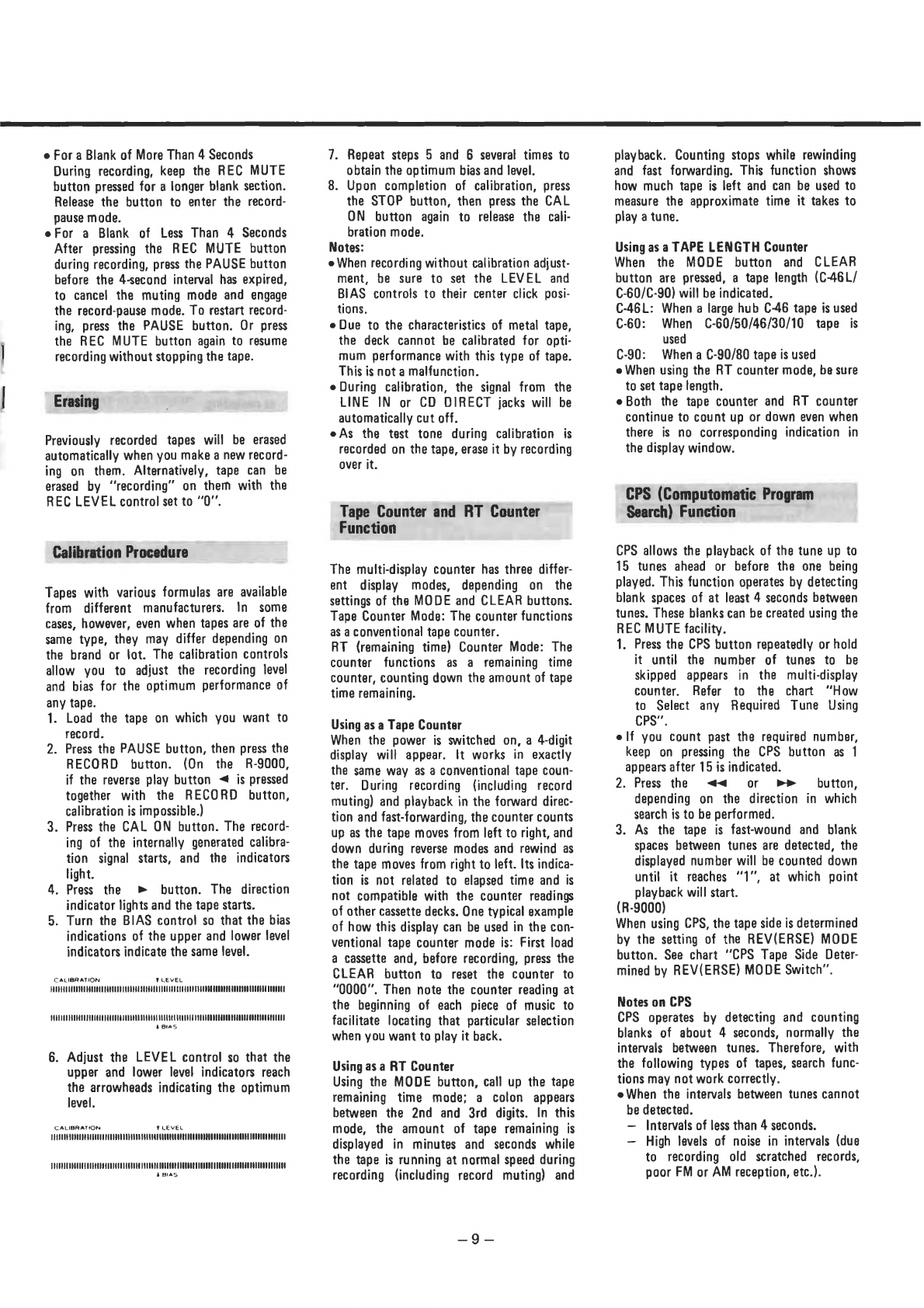
5.
Turn
the
BIAS
contro!
so
that
the
bias
indications
of
the
upper
and
lower
level
indicators
indicate
the
same
evel.
CALIBRATION
PLEVEL
FODEAAOUEUOTEODEDUEGERGUNODDSOORSTSGEARSOVINEISORESSGUACTIODEELOO
ORAL
TOOROONANGORLGIOGNONT
TOUUDOUTASARSTATOARLUREROUERTUDDEDTAEERGGT
ETA
COTE
TE
DOCERUU
OE
LAOUUEASOG
DS
CURR
AOO
GETTTT
&
BIAS
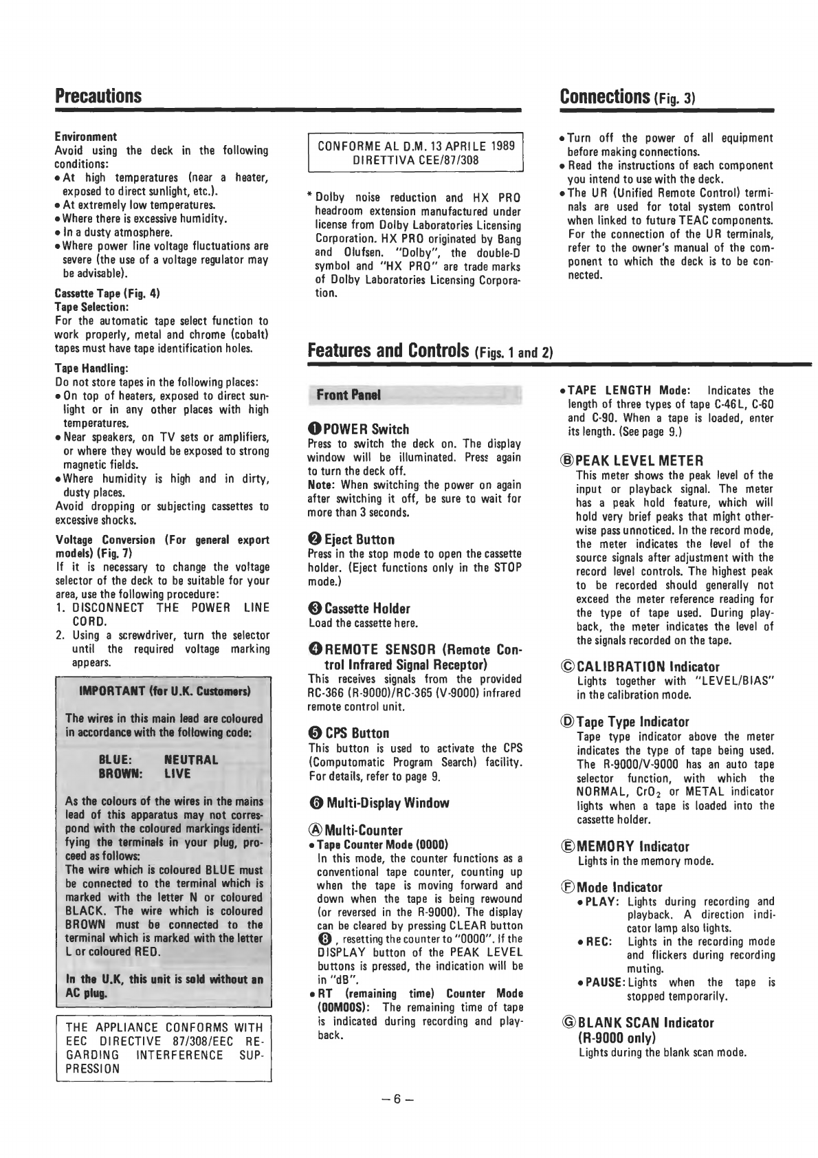
6.
Adjust
the
LEVEL
control
so
that
the
upper
and
lower
level
indicators
reach
the
arrowheads
indicating
the
optimum
level.
CALIBRATION
T
LEVEL
VHVSUAGAOGCONUATERUUGRUUODEDUORSSONERANUGUCLCUOUGGURHIGGGUODOGRGUUDEROUDEOOG
DONRNOOOOIIND
VEAUOLUDDGGOELOUEEUDDAOGEGOOLAONOEG
ISOUGRUNORNGOEANGGOGRONSRUDEUGGODN
LAORNGO
RGU
NOOR
NIINO
Aas
7.
Repeat
steps
5
and
6
several
times
to
obtain
the
optimum
bias
and
level.
8.
Upon
completion
of
calibration,
press
the
STOP
button,
then
press
the
CAL
ON
button
again
to
release
the
cali-
bration
mode.
Notes:
e
When
recording
without
calibration
adjust-
ment,
be
sure
to
set
the
LEVEL
and
BIAS
controls
to
their
center
click
posi-
tions.
eDue
to
the
characteristics
of
metal
tape,
the
deck
cannot
be
calibrated
for
opti-
mum
performance
with
this
type
of
tape.
This
is
not
a
malfunction.
e
During
calibration,
the
signal
from
the
LINE
IN
or
CD
DIRECT
jacks
will
be
automatically
cut
off.
eAs
the
test
tone
during
calibration
is
recorded
on
the
tape,
erase
it
by
recording
over
it.
Tape
Counter
and
RT
Counter
Function
The
multi-display
counter
has
three
differ-
ent
display
modes,
depending
on
the
settings
of
the
MODE
and
CLEAR
buttons.
Tape
Counter
Mode:
The
counter
functions
as
a
conventional
tape
counter.
RT
(remaining
time)
Counter
Mode:
The
counter
functions
as
a
remaining
time
counter,
counting
down
the
amount
of
tape
time
remaining.
Using
as
a
Tape
Counter
When
the
power
is
switched
on,
a
4-digit
display
will
appear.
It
works
in
exactly
the
same
way
as
a
conventional
tape
coun-
ter.
During
recording
{including
record
muting)
and
playback
in
the
forward
direc-
tion
and
fast-forwarding,
the
counter
counts
up
as
the
tape
moves
from
left
to
right,
and
down
during
reverse
modes
and
rewind
as
the
tape
moves
from
right
to
left.
Its
indica-
tion
is
not
related
to
elapsed
time
and
is
not
compatible
with
the
counter
readings
of
other
cassette
decks.
One
typical
example
of
how
this
display
can
be
used
in
the
con-
ventional
tape
counter
made
is:
First
load
a
cassette
and,
before
recording,
press
the
CLEAR
button
to
reset
the
counter
to
“0000”.
Then
note
the
counter
reading
at
the
beginning
of
each
piece
of
music
to
facilitate
locating
that
particular
selection
when
you
want
to
play
it
back.
Using
as
a
RT
Counter
Using
the
MODE
button,
call
up
the
tape
remaining
time
mode;
a
colon
appears
between
the
2nd
and
3rd
digits.
In
this
mode,
the
amount
of
tape
remaining
is
displayed
in
minutes
and
seconds
while
the
tape
is
running
at
normal
speed
during
recording
(including
record
muting)
and
playback.
Counting
stops
while
rewinding
and
fast
forwarding.
This
function
shows
how
much
tape
is
left
and
can
be
used
to
measure
the
approximate
time
it
takes
to
play
a
tune.
Using
as
a
TAPE
LENGTH
Counter
When
the
MODE
button
and
CLEAR
button
are
pressed,
a
tape
length
(C-46L/
C-60/C-90)
will
be
indicated.
C-46L:
When
a
large
hub
C-46
tape
is
used
C-60:
When
C-60/50/46/30/10
tape
is
used
C-90:
When
a
C-90/80
tape
is
used
e
When
using
the
RT
counter
mode,
be
sure
to
set
tape
length.
eBoth
the
tape
counter
and
RT
counter
continue
to
count
up
or
down
even
when
there
is
no
corresponding
indication
in
the
display
window.
CPS
(Computomatic
Program
Search)
Function
CPS
allows
the
playback
of
the
tune
up
to
15
tunes
ahead
or
before
the
one
being
played.
This
function
operates
by
detecting
blank
spaces
of
at
least
4
seconds
between
tunes.
These
blanks
can
be
created
using
the
REC
MUTE
facility.
1.
Press
the
CPS
button
repeatedly
or
hold
it
until
the
number
of
tunes
to
be
skipped
appears
in
the
multi-display
counter.
Refer
to
the
chart
“How
to
Select
any
Required
Tune
Using
CPS”.
elf
you
count
past
the
required
number,
keep
on
pressing
the
CPS
button
as
1
appears
after
15
js
indicated.
2.
Press
the
<@<¢
or
-®
—
button,
depending
on
the
direction
in
which
search
is
to
be
performed.
3.
As
the
tape
is
fast-wound
and
blank
spaces
between
tunes
are
detected,
the
displayed
number
will
be
counted
down
until
it
reaches
“1”,
at
which
point
playback
will
start.
(R-9000)
When
using
CPS,
the
tape
side
is
determined
by
the
setting
of
the
REV(ERSE)
MODE
button.
See
chart
‘CPS
Tape
Side
Deter-
mined
by
REV(ERSE)
MODE
Switch”.
Notes
on
CPS
CPS
operates
by
detecting
and
counting
blanks
of
about
4
seconds,
normally
the
intervals
between
tunes.
Therefore,
with
the
following
types
of
tapes,
search
func-
tions
may
not
work
correctly.
e
When
the
intervals
between
tunes
cannot
be
detected.
—
Intervals
of
less
than
4
seconds.
—
High
levels
of
noise
in
intervals
(due
to
recording
old
scratched
records,
poor
FM
or
AM
reception,
etc.).