AMPHIBICO Genesis User manual

HOUSING FOR THE SONY NEX FS-100
INSTRUCTION MANUAL

Table of content
Introduction and features Page 1
Unpacking your housing Page 2
Housing controls description Page 3
Preparing camcorder and housing Page 4 to 7
Housing and camcorder operation Page 8 to 12
Specications Page12
Maintenance Page 13
Accessories Page 14
Shooting tips Page 15
Warranty conditions Page 16
INTRODUCTION & FEATURES
GENESIS FS100
Marine housing for the Sony NEX-FS100U
The NEW Amphibico GENESIS housing for the Sony FS100U NXCAM HD PRO camcorder is built with
the same high quality solid aluminum construction as our previous PRO line of housings, no compromise
was taken to create the New “GENESIS” line from Amphibico. Keeping in mind total ergonomics and
underwater balance, its compact design with an intergraded electronic grip system makes the unit extre-
mely user friendly underwater.
This full featured housing will provide access to all key camcorder functions to depths of 330 feet (100
meters). Amphibico’s high quality full zoom-through 94° optics (optional) will complement the package.
Features & Controls:
- 14 Electronic push button controls to access over 25 functions
- Power On/Off
- Record/Standby
- Control Panel for menu access to camcorder functions
- Proportional Manual Focus
- Proportional Manual Zoom knob
- Manual White Balance
- Manual Iris
- Manual Gain
- Manual Shutter Speed
- Sensitive Hydrophone
- Moisture sensor alarm
- Tallylightashesgreenwhilelming
- 3 Auxiliary ports
- Bayonet lens mounting system
- Conveniently designed to accept Aquatica ports
Page 1

UNPACKING YOUR HOUSING
Before unpacking your housing kit, inspect the shipping box as well as all contents for damage during
shipping.
If damage has occurred, please contact the shipping company immediately.
Every Amphibico Housing is pressure tested prior to shipping. However, damage may have occurred
during shipping. It is strongly recommended to test dive the housing once without camcorder installed to
insure the housing is water tight.
This instruction manual assumes that the user is already familiar with the SONY® NEX-FS100U
camcorder. If not, please read instruction manuals thoroughly before beginning to use the housing.
Your GENESIS FS100 underwater housing comes to you as follows:
A) Marine Housing
B) Removable / lockable camcorder saddle (shipped in its position inside the housing)
C) O-ring kit (# ACOR-0124) with container of silicone grease
D) Instruction manual and warranty card
Page 2
U
B
L
R
I
G
C
N
A
I
N
R
-
T
O
MONTREAL, CA NADA
TEL. 514-737-9481
WWW.AQUATICA.CA
PLEASE REFER TO OWNER MANUAL FOR PROPER USE.
ACCIDENTAL DAMAGE, SAND OR DIRTON O-RINGS,
THREADS OR SEALING SURFACES MAY PREVENT AN
ADEQUATE SEAL. IT IS THE
RESPONSAB ILITY
OF THE
CUSTOMER TO TEST THE SEALS BEFORE EACH DIVE,
BEFORE INSTALLATION OF THE CAMERA:
IMMERSE THE HOUSING WITH THE PORTAND
BULKHEAD CONNECTIONS TO BE USED ON THE DIVE
IN SHALLOW WATER FOR THIRTY SECONDS
(MINIMUM) , AND INSPECT THOROUGHLY FOR LEAKS
BEFORE INSTALLING CAMERA EQUIPMENT.
THE
AQUATICA WARRANTY
DOES NOT APPLY IN THE
EVENT OF AFAILURE TO PERFORM THIS “SEAL TEST”
OR IN THE ABSENCE OF EVIDENCE OF A DEFECT IN
THE MANUFACTURE OF THE PRODUCT.
WARNING
Frontports
Qty : 1
Main Inner O-rin g
Qty : 1
Main Outer O-rin g
Qty : 1
O-ringLubricant
Qty : 1
FS-100 maintenance O-ringkit
HOUSING FOR THE SONY NEX FS-100
INSTRUCTION MANUAL

1
2
3
4
5
5
5
5
5
10-24
10-24
1/4"-20
5
5
3
4
2
1
6
6
6
7
7
7
8
9
10
11
12
13
14
15
17
9
12
13
14
16
17
9
10
4
3
18
17
19
19
21
14 13 21 12
16
12
22 20
43
18
1/4"-20
3/8"-16
1/4"-20
Bottom view
Side view
Side view
1/4"-20
1/4"-20
20
PUSH
AB
22
HOUSING CONTROLS
1-Right Electronic Grip
2-- Iris Wheel
3- Left Electronic Grip
4-- Focus Wheel
5--Accessory Mounting Holes 2 x 1/4» -20, 2 x 10-24
6- Carry Handle & trim weigh bracket mounting Rail
7- LCD Display Window
8-Rear bulkhead hinge
9- Auxiliary port
10- Auxiliary port
11- Auxiliary port
12- Hydrophone
13- Bayonet Mount Lens system
14- Bayonet port lock release knob
15-Zoom housing gear
16-Zoom knob
17-Anode
18- Menu Control Panel
19-mounting holes 1/4-20 x 3
20-housing tray
21-maintence plug
22-Rear door latch

Page 4
PREPARING CAMCORDER & HOUSING
OPENING THE HOUSING
Sitthehousingonaatsurface.Pressandrotatebothsafety
latches counter clockwise simultaneously until the rear door
opens.
REMOVING THE SADDLE
1. Push the saddle locking mechanism as indicated in order to
release the saddle from its locked position.
2. Use the handle to pull the saddle completely out of the housing.
SETTING THE CAMCORDER
1.Removehandcradle,mic.supportholderandviewnderhoodfromcamcorder.Itshouldbelikethis
image.
2.RotateandiptheLCDpaneltorestoreitbacktothe
original position with the LCD screen facing out.
- Open support holder to expose the mounting screws.
3. Set display output to “ALL OUTPUT” and
set all markers to OFF if using an external monitor
4. Set AUTO LOCK switch to the manual.
5 . Audio Settings
- Set Input 2 to MIC
- Set CH1 & CH2 TO “INPUT 2”
- Set audio levels to manual and set dial to level 10 for
maximum hydrophone performance.

Page 5
PREPARING CAMCORDER & HOUSING
INSTALLING THE SADDLE
Place the saddle under camcorder with its handle pointing the back of the
camcorder. Align the thumb screw’s saddle and guide pin with the camcor-
der’s tripod mounting holes. Hand tighten the thumb screw to secure the
saddle to the camcorder.
CONNECTING THE SADDLE
REMOTE: Connect the cable from the rear of the saddle to the
camcorders REMOTE jack.
AUDIO: Connect the XLR microphone connector to the
camcorder’s INPUT 2 MIC jack, located on the rear of
camcorder.
VIDEO: Connect the yellow RCA jack to VIDEO OUT yellow jack on rear of
camcorder
PREPARING CAMCORDER & HOUSING
PLACING THE CAMCORDER INTO THE HOUSING
By now the camcorder is set, installed to the saddle and ready to be placed
inside the housing.
1. Turn ON the camera.
2. Line up the camcorder and saddle with the docking rails found on the left
and right sides inside the housing. Watch the cables !
3. Insert the camcorder and slide it all the way until the saddle connector makes contact with the docking tray
connector. At this point the saddle lock should have engaged on the left side of saddle.
CLOSING THE HOUSING
1. While the housing is open, inspect the two o-rings and the sealing surface for dirt and debris. If necessary, clean
them with a lint free tissue. Make sure that the two o-rings and the sealing surface are clean. Then apply a small
amount of lubricant (supplied) to the o-rings.
NOTE: If you have to change your o-rings, make sure you are using the o-rings provided with the package. Using
different o-rings than those in the o-ring kit may cause the housing to leak and result in damage.
2. Make sure that the saddle cables do not block the sealing
surface. If any cable gets pinched, the system might be intermittent or not functioning at all. Close the rear door
until the latch begins to engage.
INPUT 2
COMPONENT OUT
REMOTE

Page 6
MOUNTING THE PORT
Before mounting the port on the housing always ensure that the port O-ring is clean, lubricated and proper-
ly seated in its groove and that he sealing surface on the housing is clean and free of physical damage.
The GENESIS HD Digital Housing System features a bayonet mount #13 equipped with a locking mechanism
#14 If there is already a port or extension mounted on the housing and you wish to remove it, simply pull
the lock lever (key 18) until it stop, rotate the port counter clockwise and carefully pull out, and put it aside
in a safe place with the port lens delicate surface protected.
To mount the port or extension ring simply:
1. Place the housing on its back on a soft steady surface.
2. Place the port or extension ring inside the main port of
the housing. Align one of the four alignment notches with the
opening of the housing.
3. Place your hands on opposite sides of the port or exten-
sion ring.
4. Push with even force on both sides of the port or extension
ring until you feel it snap into place. Make sure the bayonet is
completely inside the housing.
5. Turn the port clockwise until it stops. Do not force, if there
is too much resistance takes the port off, check the O-ring and retry.
6. Check to ensure for the proper seating and sealing of the port or extension and that it is safely locked
on the housing.
Note: It is recommended that you familiarize yourself with this mount by trying it without the camera;
this will allows you to see the inside view of the bayonet mount and of the ports or extension rings in the
housing.
Lock
Unlock
Press to
unlock

Page 7
PREPARING CAMCORDER & HOUSING
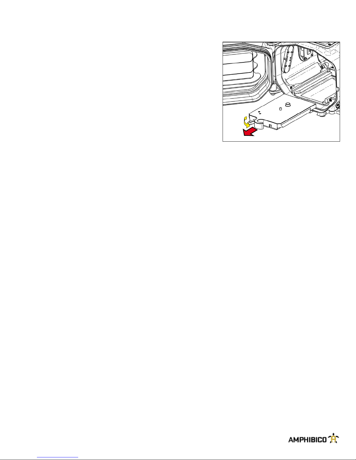
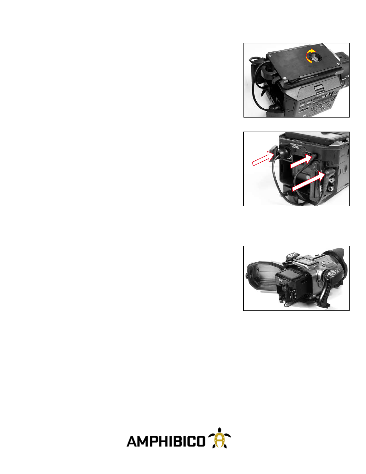
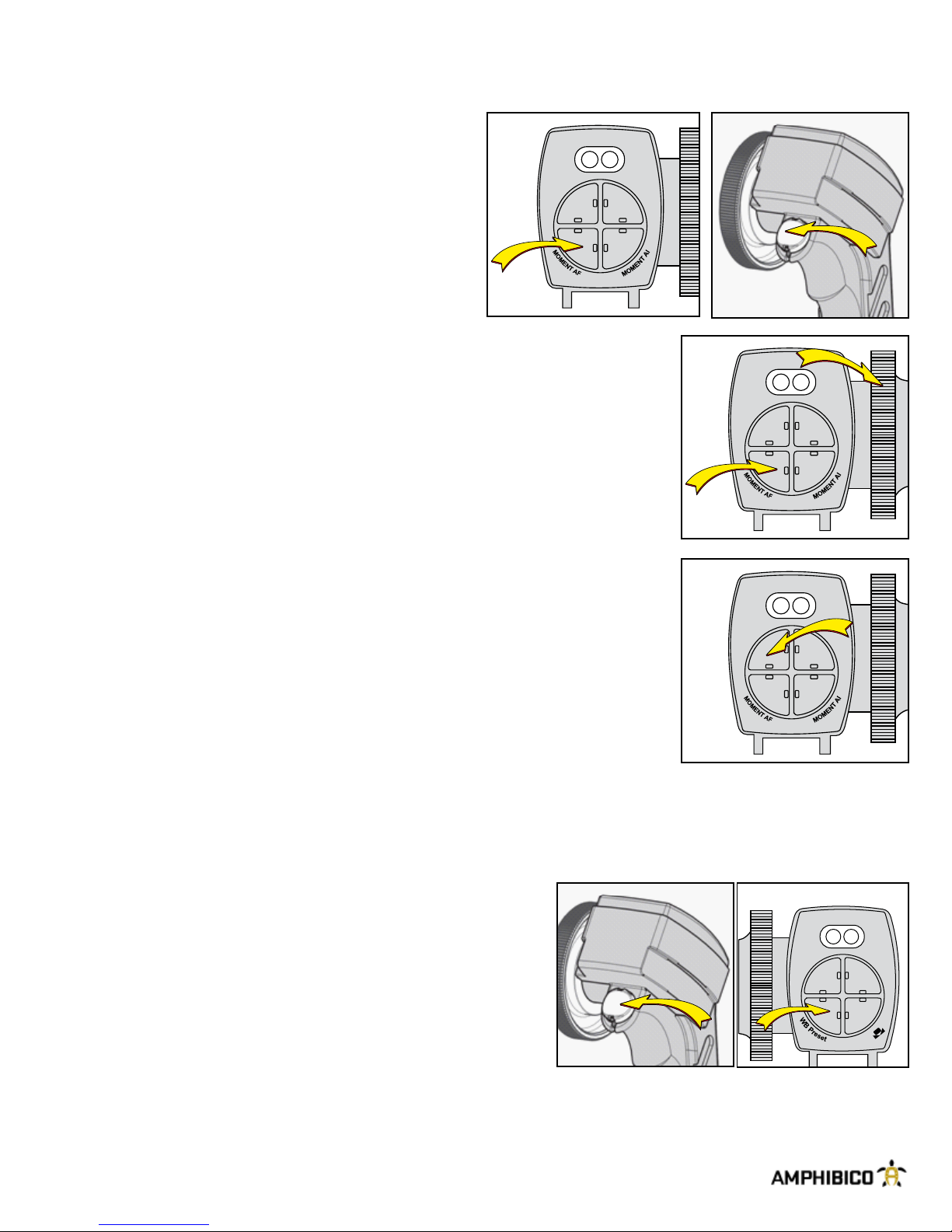
INSTALLING ACCESSORIES
The GENESIS has been equipped with mounting holes and
a railing system to accommodate for a variety of accessories.
Locations for a few of these accessories have been designated
for your convenience. However, these locations can be used
for other accessories. Some accessories like the monitor or
video lights require to be connected to the housing. Accessory
connector ports (three on the right side) for installing external
monitor.
Achieving neutral buoyancy and balance
DependingontheDomeportandlenscongurationandaddingaccessoriestothehousingmaymakeit
heavier or off balance in the water. In freshwater and seawater the GENESIS can be perfectly balanced and
neutral in buoyancy by trimming it with the optional trim weigh kit and the port of choice.
WATER ENTRY
1. Always turn housing to its ON position before entering water. To turn it ON, use the right grip trigger
button.ThisisconrmedbytheCAM.indicatorlightturningonsteadygreen.ThecamcordertopLCD
viewnderwillalsoturnON.Doingstep1willactivatethebuilt-inmoisturealarmsensorlocatedinthe
bottom of the housing.
IMPORTANT
TherightlightsonbothgripswillstartashingREDifwaterleakageoccursinsidethehousing.Remove
from
water as soon as possible, take the camcorder out of the housing and inspect all seals and the inside of
the
housing. ALWAYS REMEMBER DIVER SAFETY FIRST.
2.Lowerthehousingjustbelowthewatersurfaceinlevelpositionandholdforoneminutetoconrmthere
is no leakage in the housing. Never leap into the water while holding the housing. Always have the housing
handed to you or lowered down once you are in the water.
3. Point the lens of the housing upwards and shake off any air bubbles. It may also be necessary to gently
wipethelenswithyourngertoremovebubbles.
--------------------------------------------------------------------
Trim Weight & Handle Kit
# ACGETHK-01

Page 8
HOUSING & CAMCORDER OPERATION
The GENESIS offers a large range of electronic functions. This chapter will explain to you in detail all of
these functions.
POWER ON
The camcorder should be powered ON by default after inser-
ting it into the housing. In the event that it's not, the trigger
button on the right grip will activate the camcorder. Simply
press on it once and the CAM indicator light will turn on stea-
dygreenandthetopLCDviewnderwillalsobeturnedonto
conrmthepowerONofthecamcorder.
POWER OFF
To power off the camcorder during a dive will allow you to save on battery energy.
To do so, push and hold down on one of the Menu control panel button as indicated.
CAM MODE
The housing will set itself to record/standby mode (CAM indi-
cator LED is steady green) when initially turned ON. To record
a scene, simply press on the right grip trigger button. The
CAMindicatorLEDwillashgreenwhenrecording.Pressing
it again will bring it back to record/standby mode.
HOUSING & CAMCORDER OPERATION
ZOOMING
On the GENESIS, zooming is achieved by using the mechani-
cal knob on the left side of housing Zoom Knob
Right grip
trigger button
CAM NAV.
W
A
-
B
e
r
P
P
r
e
-
B
B
W
WB
Power ON
MENU CONTROL PANEL
Record/Standby
CAM NAV.
W
A
-
B
e
r
P
P
r
e
-
B
B
W
WB
Right grip
trigger button
Page 8

Page 9
FOCUSING
The camcorder focus on the GENESIS can be set to either
auto or manual focus. To toggle from auto to manual focus,
press down on the MOMENT AF button while holding down
the shift key, on left grip.
Manual Focus
Inmanualfocus,youcanadjustthefocusbyusingthefocuswheeltoneadjustthefocus.
Use the MOMENT AF button (by holding it down) to temporally auto focus. Letting go will
return to manual focus.
Expanded Focus
Press the EXP. FOCUS button to magnify the center of the screen when in
manual focus. Pressing it again will bring back the screen to its original size.
Focus Wheel functionality
The focus wheel is spring loaded and maintains a zero (non active) position when not in use.
DISPLAY Toggle
This function allows you to display ON or OFF the camcorder’s information
onthe camcordersLCD viewnderwhile recordingor inplayback mode.
To access this function, while holding down the shift key (left trigger button)
press the WB Preset button on the right grip.
SHUT.
IRISAF
GAIN
G
A
S
I
N
U
S
C
E
O
L
F
E
.
P
C
X
T
E
SHUT.
IRISAF
GAIN
G
A
S
I
N
U
S
C
E
O
L
F
E
.
P
C
X
T
E
Left Grip
CAM NAV.
W
A
-
B
e
r
P
P
r
e
-
B
B
W
WB
Right Grip
SHUT.
IRISAF
GAIN
G
A
S
I
N
U
S
C
E
O
L
F
E
.
P
C
X
T
E
Left
Grip Left Grip
Left
Grip
Left
Grip

Page 10
HOUSING & CAMCORDER OPERATION
WHITE BALANCE
The capability to white balance underwater plays an important
role in achieving good quality footage. This is why the GENE-
SIS offers the "One Push" white balance.
Pressing on the WB button on the right grip while holding down the shift key will allow you to tog-
gle between manual and automatic white balance. Once in manual mode, you can choose between white
balance preset, memory A and memory B, pressing down on the appropriate button found on the right grip.
Use the WB Preset button to store the adjusted white balance value in memory A or B.
MENU
To activate and deactivate the camcorders menu, press
and hold the left trigger then press the right trigger button.
Navigation Function (NAV)
To change any of the settings inside the menu or to select a
pictureprole,youneedtoactivatethenavigationfunction
(NAV)rst.Thisisdoneasfollows:Holddowntheshiftkey
while pressing down on the right grip trigger button to acti-
vate and deactivate the NAV function.
The NAV light indicator will turn on steady green when activa-
ted. Use the WB Pre-A, WB Pre-B, WB Preset & WB
onthe right grip buttons to navigate through the menu.
The execute button is the right grip trigger button.
CAM NAV.
W
A
-
B
e
r
P
P
r
e
-
B
B
W
WB
Left Grip Righ Grip
Left Grip Right Grip
CAM NAV.
W
A
-
B
e
r
P
P
r
e
-
B
B
W
WB
Right Grip

Page 11
Assign Buttons
You can also access the camcorder’s assign buttons via the control panel.
The available assign buttons are found on the control panel as follows.
S1: Assign 1
S2: Assign 2
Shift (Right trigger ) & WB Pre-A: Assign 3
S3: Assign 4
S4: Assign 5
Shift ( Right trigger) & WB Pre--B: Assign 6
Adjusting the iris
Youmustrstmakesurethattheirisissettomanual.Todoso,push
on the left grip IRIS button while holding down the shift key (left trigger
button).
In manual mode, you can adjust the aperture value of the camcorder by
holding down the shift key and turning the right grip wheel.
You can also engage Auto Iris momentarily when in manual iris by pushing on the
MOMENT AI button located on the left grip.
Right grip
trigger button
CAM NAV.
W
A
-
B
e
r
P
P
r
e
-
B
B
W
WB
S1
S2
S3
S4
Right grip
trigger button
CAM NAV.
W
A
-
B
e
r
P
P
r
e
-
B
B
W
WB
Left Grip
SHUT.
IRISAF
GAIN
G
A
S
I
N
U
S
C
E
O
L
F
E
.
P
C
X
T
E
Left grip
trigger button
CAM NAV.
W
A
-
B
e
r
P
P
r
e
-
B
B
W
WB
Left grip
trigger button
Right Grip
SHUT.
IRISAF
GAIN
G
A
S
I
N
U
S
C
E
O
L
F
E
.
P
C
X
T
E

Page 12
Adjusting the gain
Youmustrstmakesurethatthegainissettomanual.
To do so, push on the GAIN button located on the left grip
while holding down the shift key. Once activated, you can
adjust the gain by pushing on the GAIN SELECT button
located on the left grip to select one of its preset gain le-
vels (H 18db,M 9 db,L 0db).
Adjusting the shutter speed
Youmustrstmakesurethattheshutterissettomanual.
To do so, push on the left grip SHUT. button while holding
down the shift key. In manual mode, you can adjust the
shutter speed of the camcorder by holding down the shift
key and turning the left grip wheel.
SPECIFICATIONS
GENESIS FS100
Marine housing for the Sony NEX-FS100U
- Marine grade aluminum Construction
- Fully anodized with a hard coat of polyurethane powder coat paint
- All hardware is marine grade brass and stainless steel
- Marine bayonet mounted lens system
- Sensitive hydrophone to pick up high frequency sounds, such as whales and dolphins
- 3 Auxiliary ports
Weight of unit :
- On land 12lbs. (16.3kg) fully loaded w/camera NP-F970 battery.
- In freshwater and seawater the GENESIS can be perfectly balanced and neutral in buoyancy by trimming it with the optional
trim weigh kit and the port of choice
Dimensions :
- Length 10.5’’ (267mm)
- Width 13.6’’ (345mm)
- Height 6.5’’ (165mm)
- Measurements includes grips
Operating depth :
- Each unit is pressure tested to 330ft (100m)
SHUT.
IRISAF
GAIN
G
A
S
I
N
U
S
C
E
O
L
F
E
.
P
C
X
T
E
Left Grip
Left grip
trigger button
Left Grip
SHUT.
IRISAF
GAIN
G
A
S
I
N
U
S
C
E
O
L
F
E
.
P
C
X
T
E
Left grip
trigger button

Page 13
MAINTENANCE
WARNING: DO NOT leave the housing exposed to direct sunshine, as extreme heat condition can be detrimental
to certain of its components.
1. Keep housing and o-rings away from direct sunlight. Always store unit when possible away from direct sunlight
as this can dry out and crack o-rings in the housing. Ultraviolet rays can damage plastics, paint and o-rings.
2. Always rinse or soak closed housing in fresh water for 10 to 15 minutes after every use. Reach into freshwater
and operate all controls to clear salt water. Do not use solvents to clean unit. If preferred, use mild detergent and
clean freshwater.
3. Fasteners that are removable should occasionally have the threads lubricated with silicon grease.
4.Rinsecleanandremovewaterspotsfromexternalltersandlenssurfaceaftereverydiveorwaterspotsmay
build up and become impossible to remove. Dry gently with a soft, lint-free cloth.
5. Inspect housing's rear door main o-ring seals (double seals) before every dive. Make sure that there are no
cracks or misalignment in the o-ring channel and that no debris is caught on the o-rings.
6. During storage or transit, leave rear door ajar on unit to prevent damage due to extreme high pressure.
SERVICING O-RINGS
1. O-rings and sealing surface should be lightly lubricated with silicon lubricant on a regular basis. This is not ne-
cessaryaftereverydive;everytenthdiveduringregularheavyuseissufcient.Thisshouldalwaysbedonebefore
storingthehousingandbeforearstdiveaftertakingthehousingoutofstorage.
2. It is important never to use a sharp instrument when removing an o-ring as this may cause damage to the o-ring
or the o-ring groove. A hairpin or a credit card works well.
3. The removed o-ring should be examined for damage. Check to make sure that the o-ring is free from nicks and
cutsandthatitretainsitsoriginalroundprole.O-ringsthatappeartobedamagedshouldbediscardedimmedia-
tely and replaced with new o-rings.
4. Rinse the o-ring with freshwater and dry it with a clean lint free cloth.
5. Clean the o-ring grooves (where the o-rings sit) with a Q-tip. Be sure to remove any lint the Q-tip may leave
behind. Inspect the groove for damage.
6. Wipe the part of the housing that the o-ring seals against with a clean lint free cloth.
7. Re-grease the o-rings with a thin layer of silicon grease until it appears to be smooth and shiny. Do not over
greaseit,usejustenoughgreasesothattheo-ringwillpullsmoothlythroughyourngers.Excessiveamountswill
only attract dirt to the o-ring.
8. Replace o-rings in their proper position on the lens assembly and on the main door seal.

Page 14
OPTIONAL ACCESSORIES
The GENESIS offers an array of accessories and they are as follows:
-PORTS
-18407 Aquatica 9.25" Mega Dome in BK7 coated glass
-18405 Aquatica 8" Dome port
-18409 Aquatica 6" Dome port
-18410 Aquatica 4" Mini Dome in BK7 coated glass
-18428 Aquatica AF Macro port
-Extension Ring
-18463 Aquatica 21.5mm /.82" (overall 34mm/1.32")
-18462 Aquatica 39.5 mm / 1.56" (overall 52mm/2.06")
-Gears
-GRSO1855.1 18-55mm zoom gear
- Lights*
- 10 Watt Arc Light "HID Technology" with mounting arm
- 3.5” Standard LCD Monitor
- WB/Color chart slate
- 7" x 11" slate
Check out our website for more update accessories at www.amphibico.com
U
B
L
R
I
G
C
N
A
I
N
R
-
T
O
MONTREAL, CA NADA
TEL. 514-737-9481
WWW.AQUATICA.CA
PLEASE REFER TO OWNER MANUAL FOR PROPER USE.
ACCIDENTAL DAMAGE, SAND OR DIRTON O-RINGS,
THREADS OR SEALING SURFACES MAY PREVENT AN
ADEQUATE SEAL. IT IS THE
RESPONSAB ILITY
OF THE
CUSTOMER TO TEST THE SEALS BEFORE EACH DIVE,
BEFORE INSTALLATION OF THE CAMERA:
IMMERSE THE HOUSING WITH THE PORTAND
BULKHEAD CONNECTIONS TO BE USED ON THE DIVE
IN SHALLOW WATER FOR THIRTY SECONDS
(MINIMUM) , AND INSPECT THOROUGHLY FOR LEAKS
BEFORE INSTALLING CAMERA EQUIPMENT.
THE
AQUATICA WARRANTY
DOES NOT APPLY IN THE
EVENT OF AFAILURE TO PERFORM THIS “SEAL TEST”
OR IN THE ABSENCE OF EVIDENCE OF A DEFECT IN
THE MANUFACTURE OF THE PRODUCT.
WARNING
Frontports
Qty : 1
Main Inner O-rin g
Qty : 1
Main Outer O-rin g
Qty : 1
O-ringLubricant
Qty : 1
FS-100 maintenance O-ringkit

Page 15
TIPS & TRICKS
General Shooting Tips
1. Best results will be obtained with natural light if the sun is directly overhead during calm water periods.
2. Placing the sun behind your shoulder during shooting will produce the best colors.
3. Wide angle is the preferred focus setting for best results with subject, as close as possible to the housing.
This
will reduce the water column and the amount of particles between subject and lens.
4. Zooming during shooting is not recommended unless absolutely necessary as telephoto will magnify parti-
cles.
Swimmingtowardsubjectisamuchmorevisuallypleasinglmingmethod.
5. Useimagestabilizerifavailableonyourcamerawhenlmingmacrotominimizecameramovementduring
highmagnication.Imagestabilizerisnotascriticalwhileusingwideangleandwillusebatterypower
unnecessarily.
6. Buoyancy control is one of the most important aspects of underwater videography and diving in general.
Avoid
disturbing bottom silt and contacting delicate reef structures. Work on controlling your breathing and your buoyan-
cy.
Your video will be much more visually appealing. You are trying to make yourself a steady shooting plat-
form.
The less movement you make , the better your video will be. Work on attaining a comfort zone underwater. The
more comfortable you are underwater, the more controlled your breathing will be and the steadier your video will
be.
7. In low light situations, add light with optional Amphibico video lights for brighter and more vibrant colors. As
lightlevelfallssodoescolorsaturation.Lightswillalsoprovidenecessaryllduringdaylightshooting.
Audio Tips
To eliminate any faint background noises which may come from an internal device, it is recommended to switch the
audio settings of CH1 on your camcorder from auto to manual. The audio level for CH1 should be set anywhere
between 3 and 4 once in manual mode.
Trouble Shooting
The GENESIS marine housing is equipped with a built in dia-
gnostic test mode. To activate it, simply push and hold one of
the buttons on the control panel as shown bellow while turning
on the unit with the right grip trigger button. Once activated, you
can test all the push buttons and wheels to see if the function
properly. Pushing a button or turning a wheel will light up a diffe-
rent indicator light making it either red or green. Push and hold
one of the buttons on the control panel as shown bellow to exit
diagnostic test mode.
TEST MODE ENTRY
TEST MODE EXIT

Page 16
WARRANTY
Please take time to register your product on line at the following secure WEB site
“www.amphibico.com”. This way your product will be recorded in our data base in
case it gets lost or stolen. It also allows us to contact you in the unlikely event that
asafetynotication is required on yourproduct.Thisonlineproductregistration
eliminatestheneedforyoutolloutthewarrantycardthatwassuppliedwithyour
Amphibico product.
All Amphibico products are guaranteed against defects in material or workmanship for two full years from
the date of purchase for consumer use. These same products when used commercially will carry a 90-day
warranty. No statutory warranty applies. Cameras housed in Amphibico housings are not covered under
this warranty and ANY WATER DAMAGE SUSTAINED DUE TO INSTALLATION ERROR OR FOR ANY
OTHER REASON IS NOT THE RESPONSIBILITY OF AMPHIBICO INC. Therefore the appropriate insu-
rance should be maintained by the user.
Subjecttothetermsandconditionsspeciedhereunder,AmphibicoInc.agreestocorrect,eitherbyrepair
or by replacement, any defect in material or workmanship which develops within one year after delivery of
the product to the original purchaser.
Repair or replacement is provided in the event that investigation and factory inspection by Amphibico Inc.
discloses that such a defect has developed under normal and proper use. No warranty is granted concer-
ning components, accessories, or devices not manufactured by Amphibico Inc.
AMPHIBICO INC. SHALL BE RELEASED FROM ALL OBLIGATIONS UNDER ITS WARRANTY IN THE
EVENT REPAIRS OR MODIFICATIONS ARE MADE BY PERSONNEL OTHER THAN ITS OWN OR
AUTHORIZED
(IN WRITING) SERVICE PERSONNEL.
AmphibicoInc.,initscontinuedcommitmenttoprovideexcellenceintheeldofunderwaterimaging,re-
servestherighttochangespecicationsatanytime,withoutnoticeandwithoutincurringanyobligations
to incorporate new features in equipment previously sold.
CONDITIONS
Registration:Theattached(warranty)cardmustbelledoutandmailedtoAmphibicoInc.withinfourteen
(14) days after retail purchase.
Repairs: The unit must be returned freight prepaid to Amphibico Inc. The returned documents must show
Serial N0. and be marked “ CANADIAN GOODS RETURNED.” No returns will be accepted without Amphi-
bico Inc return authorization number.
Table of contents
Other AMPHIBICO Camera Accessories manuals

AMPHIBICO
AMPHIBICO Dive Buddy EVO HD User manual

AMPHIBICO
AMPHIBICO Dive Buddy EVO HD User manual

AMPHIBICO
AMPHIBICO Phenom FX21 User manual

AMPHIBICO
AMPHIBICO HD Wave WAVH0760 User manual

AMPHIBICO
AMPHIBICO genesis fs-700 User manual

AMPHIBICO
AMPHIBICO Handycam HDR-FX1 User manual

AMPHIBICO
AMPHIBICO VH-2000 Operating and maintenance manual

AMPHIBICO
AMPHIBICO PHENOM NX5 SE User manual

AMPHIBICO
AMPHIBICO Video Camera Housing User manual