Amphony L1500 Manual

RR
User and Installation
Guide
5.8 GHz DIGITAL Wireless
Audio Transmitter / Receiver
Model 1500

Contents
Unpacking
Connecting the transmitter
Placing the transmitter
Connecting the receiver
Operating the transmitter and receiver
Troubleshooting
Technical specifications
Safety information
Your warranty
....................................................................................... 2
.............................................................. 2
.................................................................... 5
.................................................................. 6
............................................ 8
............................................................................ 10
................................................................ 12
......................................................................... 13
................................................................................ 15

User and Installation Guide
RR
Step 1Step 1 Connecting the transmitter
The transmitter connects either to a standard line-out audio interface via the
supplied RCA cable or to an amplified speaker output via the supplied short
speaker cables.
If the transmitter is connected via speaker cables, observe the polarity of the
cable connection to ensure that the transmitter will be fed with a correct
polarity signal. If one of the cables is switched (reversed), one speaker will
receive an opposite polarity signal which will degrade sound performance.
The transmitter can also be connected to other audio outputs by using an
appropriate adapter.
Connect the supplied small AC adapter’s barrel-shaped plug into the DC 9V
jack, and then plug the transformer into a standard AC outlet. We recommend
the use of a surge protector to protect the transmitter from power surges.
Unpacking: Check that this package contains:
One 5.8 GHz Digital Audio transmitter, one 5.8 GHz Digital Audio receiver,
two AC adapters, two dual RCA audio cables.
ATTENTION!
Do not use both the speaker cables and RCA cable. Do not
connect speakers to the transmitter.
Page 2

User and Installation Guide
RR
Page 3
LRDC 9V
L R
L R
AUDIO
LINE OUT
Audio Source
Transmitter
DC 9 V
300 mA
Power outlet
AC adapter
Using the transmitter RCA audio input:

LRDC 9V
L R
Using the transmitter speaker audio input:
Transmitter
DC 9 V
300 mA
Power outlet
AC adapter
L R
SPEAKER OUT
Audio Source
User and Installation Guide
RR
Page 4

User and Installation Guide
RR
Page 5
Step 2Step 2 Placing the transmitter
The operating range essentially depends on how many obstacles there are
between the transmitter and the receiver. Therefore, it should be carefully
considered where to place the transmitter.
Below, two examples are given. In the first example, there are 4 walls
between the transmitter and the receiver. The transmission may be
interrupted. By locating the transmitter such as in the second example,
reliable transmission to all of the 6 rooms is possible.
Also, the elevation of the transmitter as well as the presence of reflecting
walls will influence the range.
It is suggested to experiment in order to find the best location for the
transmitter.
Example 1: Poorly chosen
transmitter location Example 2: Improved
transmitter location

User and Installation Guide
RR
Page 6
Step 3Step 3 Connecting the receiver
The receiver connects to a line-in interface of an active speaker or external
amplifier via the supplied RCA cable.
If no line-in interface is available, the receiver can also be connected to other
audio inputs by using an appropriate adapter. It should be noted that the
maximum audio level of the receiver output is 1 Vrms (V ± 1.4 V maximum).
pp
Ensure that the connected audio device will accept this audio level.
Connect the DC power input with the supplied AC adapter. The use of a surge
protector is recommended to protect the receiver from power surges which
may damage the receiver or may cause audio dropouts.
For best reception, the receiver should be placed right side up and with the
front of the receiver facing toward the transmitter. The receiver employs a
directional antenna which prefers signals arriving at the front of the receiver.
Example 1: Receiver placed
on top of a speaker Example 2: Receiver mounted
vertically behind a speaker
Transmitter Receiver
Transmitter
Active
speaker
Receiver
line of sight indirect connection
(reflected signal)
Active
speaker

User and Installation Guide
RR
Page 7
L R
AUDIO
LINE IN
Audio Input
(Active speaker)
Receiver
DC 9 V
300 mA
Power outlet
AC adapter
DC 9V
L R
ATTENTION! Do not connect the receiver audio output directly to passive
speakers or other low impedance drains as this may damage
the receiver! The receiver audio output cannot drive passive
speakers or headphones directly. For those devices, an
external amplifier is required.

User and Installation Guide
RR
Page 8
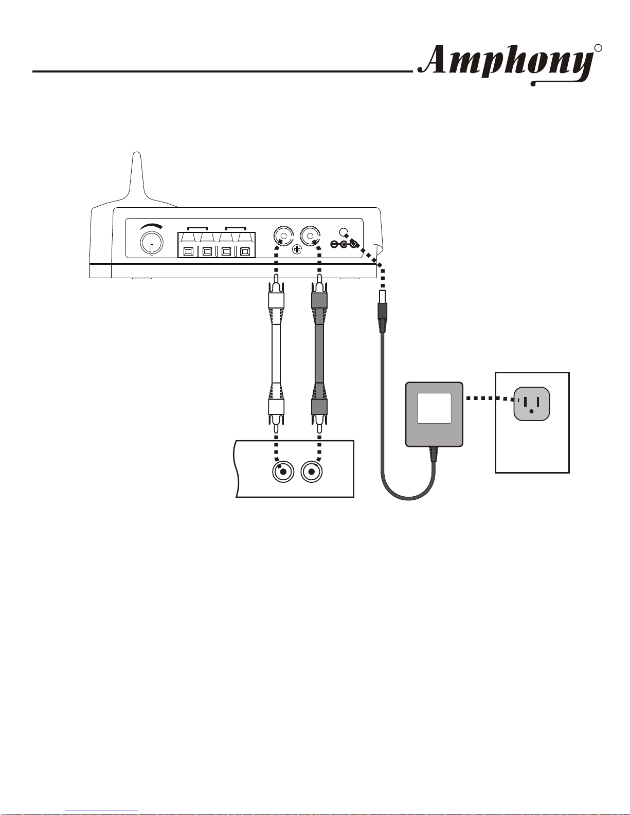
Step 4Step 4 Operating the transmitter and receiver
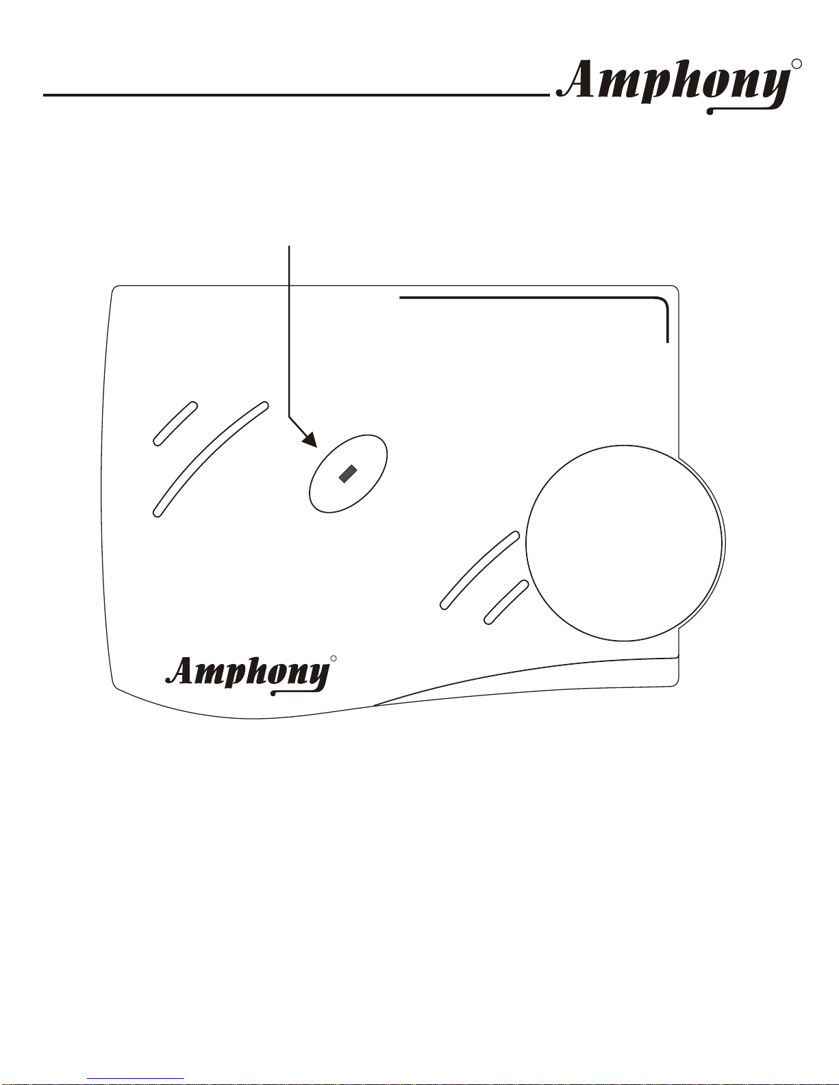
After powering up the transmitter, the transmit light will light for
approximately 5 seconds while the transmitter initializes.
After initialization, the transmit light will go out.
Once audio is detected at the audio input, the transmit light will light and the
transmitter will transmit the audio signal.
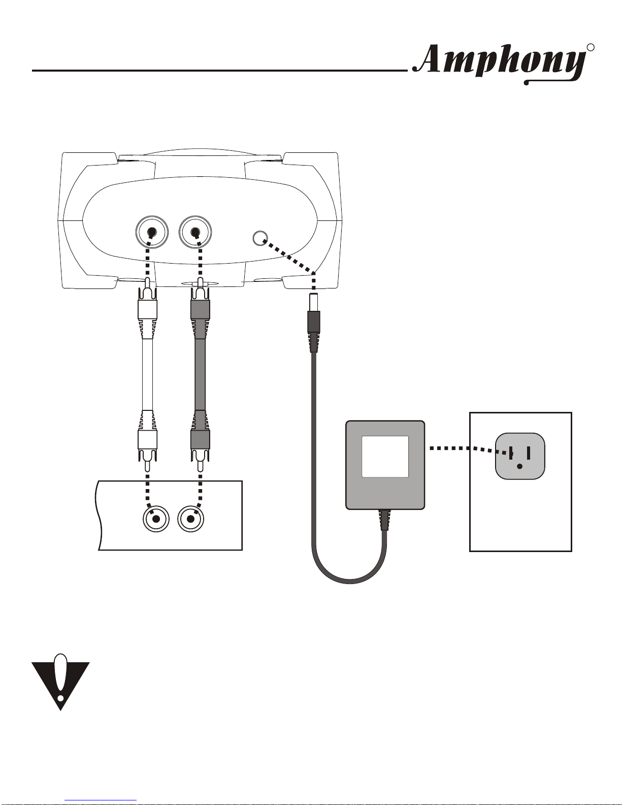
Switch on the speakers connected to the receiver. The audio will now be
played back through the speakers.
In order to properly set the transmitter volume control, turn the volume of the
speakers connected to the receiver to a low setting. Then feed a signal with
the highest possible volume to the transmitter. Set the transmitter volume
control to the highest level while there is still no clipping / distortion of the
audio signal. Then set the volume of the connected speakers to the desired
level.
When no audio is present anymore, the transmitter will
go into standby mode after approximately 1 minute. The transmit light will go
out. During standby mode, no signal is transmitted.
Once the receiver is powered up and a valid audio signal is detected, audio
will be output at the receiver line output. When no valid audio signal is
received, the receiver audio output will be muted and the receiver will go into
standby mode.
If the transmitter or receiver are not used for an extended period of time,
remove the AC adapters from the power outlet.
If the transmitter level is set too low, the dynamics of the transmission are
not fully used. If the level is set too high, audio clipping (distortion) will occur
inside the transmitter.

User and Installation Guide
RR
Page 9
5.8 GHz Digital Audio Transmitter5.8 GHz Digital Audio Transmitter
RR
TRANSMIT
TRANSMIT
Transmit light

User and Installation Guide
RR
Page 10
Troubleshooting
Problem Possible Cause Solution
The transmitlight
does not go on after
DC power is applied
to the transmitter
Faulty AC adapter
or faultypower outlet Check the power outlet and
the ACadapter; if possible,
check for correct voltage of
the ACadapter.
No audio present at
audio input Check the audio connection
to the transmitter and ensure
that there is audio present.
The transmitlight
goes out after a few
seconds and does
not light again Transmitter hung up Disconnect and then
reconnect DC power.
Faulty AC adapter
or faultypower outlet See under “Faulty AC adapter
or faultypower outlet“ above.
Transmitter volume
control set toolow Adjust the transmitter volume
control.
No audio at receiver
Strong interference See under “Strong
Interference“ on next page.
Transmitter volume
control set too high Adjust the transmitter volume
control until clipping stops.
Audio is distorted
Strong interference See under “Strong
Interference“ on next page.
Transmitter volume
control set toolow Adjust the transmitter volume
control to achieve the desired
audio level.
Speaker volume
control set toolow Adjust the speaker volume
control to achieve the desired
audio level.
Speaker audio level
is toolow
Audio signal too
weak Increase the output level of
the audio source (connect
transmitter to an adjustable
output by using an adapter if
necessary).

User and Installation Guide
RR
Page 11
For more information, visit www.amphony.com
Problem Possible Cause Solution
Strong interference Interference preventing
proper reception of the audio
signal can be caused by 5.8
GHz cordless telephones or
wireless networks. Either
eliminate the interference,
locate the base unit of the
cordless phone in another
room, set the wireless
network to use the 5.1 GHz
frequency band rather than
5.8 GHz, relocate the
transmitter, relocate or
reorient the receiver.
Audio drops out
intermittently or
crackles
Unstable power
supply Ensure that the power outlet
delivers a stable voltage. Very
strong surges may cause
audio dropouts. Try usinga
surge protector.
Strong interference See under “Strong
Interference“ above.
Transmitter volume
control set too low Adjust the transmitter volume
control.
Audio is noisy
Audio signal too
weak See under “Audio signaltoo
weak“ on previous page.
Strong interference See above.Transmitter range is
extremely short Too many obstacles Audio will drop out if there are
too many obstacles between
the transmitter and the
receiver, try relocating the
receiver or transmitter to
improve reception.

User and Installation Guide
RR
Page 12
Technical Specifications
Transmitter:
Audio transmission method: Digital
Transmitter frequency: 5.8 GHz
Error correction: 1/2 rate FEC
Transmitted data rate:> 3 Mbps
Transmitter operating range:
max. 200 ft. line of sight, max. 50 ft. through walls and ceilings
Audio sampling method: 128 times oversampling
Receiver:
Output level: 1 Vrms
Frequency response: 2 Hz … 23 kHz
Signal-to-noise ratio: 95 dB (Transmitter / Receiver,A-weighted)
Total harmonic distortion: typ. 0.006 % (- 84 dB)
Overall audio latency: < 1 ms
Channel separation: typ. 86 dB

User and Installation Guide
RR
Page 13
IMPORTANT SAFETY INFORMATION ATTENTION!
READ THESE SAFETY INSTRUCTIONS CAREFULLY AND
HEED ALL WARNINGS IN THIS MANUAL.
POWER SOURCE
To avoid product malfunction, and to protect against electric shock, fire or personal
injury, please observe the following:
• This product has been designed to work with 120-volt AC current using the
supplied AC adapters. Connection to a line voltage other than that or use of non-
compatible AC adapters may create a safety and fire hazard and may damage
the product.
• Do not run power cords under rugs or carpets or place heavy objects on them.
• Damaged or deformed power cords are hazardous and should be replaced
immediately by a qualified service technician.
LOCATION
• Do not use this product outdoors or in cars.
• Air vents are provided at the bottom of the receiver to prevent excessive
temperatures inside the unit. Do not place the receiver in closed spaces, cover it,
or otherwise block the vents.
• Do not place this product in direct sunlight, or near heat sources.
• Keep this product away from strong magnetic objects.
VOLUME CONTROL
• Do not turn up the volume while listening to a portion with very low level input or
no audio signal to avoid damage to your speakers during a peak level audio
portion.
• Turn the speaker volume control to minimum prior to connecting or disconnecting
the transmitter or receiver and prior to switching audio sources as this may cause
loud clicks which can damage your speakers.
CARE
• Do not insert or drop anything into the receiver through the air vents as this could
cause serious damage, possibly resulting in fire.
• Do not place any object containing water or other liquids on this product.
• Do not remove the cabinet. Touching parts inside the cabinet could result in
electric shock and damage to the product.

User and Installation Guide
RR
Page 14
NON-USE PERIODS
• When the product is not being used for a long period of time, unplug the product.
CLEANING
• Unplug the product before cleaning.
• When the system gets dirty, wipe it with a clean, soft cloth. If necessary, wipe it
with a soft cloth, slightly dampened with soapy water. Wipe dry immediately with
a dry cloth.
• Never use benzene, aerosol cleaners, thinner, alcohol or any volatile cleaning
agent.
• Do not use abrasive cleaners, as they may damage the finish.
SERVICE
• Do not open the cabinet of any components. Opening the cabinets may present a
shock hazard, and any modification to this product will void your warranty.
• Do not attempt to service the unit yourself. If liquid or any metal objects such as
paper clips, wire or staples accidentally fall inside, disconnect the product from
the power source immediately, and consult an authorized service center.
• Please refer any service to an authorized Amphony service center.
Copyright (C) 2007 Amphony.All rights reserved.
The information contained herein is subject to change without notice.
Revisions may be issued to advise of such changes and/or additions.
All product names, trade names, or corporate names mentioned in this
document are acknowledged to be the proprietary property of the registered
owners.
FCC ID PMJT1500
This device complies with part 15 of the FCC Rules. Operation is subjected to
the following two conditions: 1) This device may not cause harmful
interference and 2) this device must accept any interference received,
including interference that may cause undesired operation.
Caution: Any changes or modifications not expressly approved by the party
responsible for compliance could void the user's authority to operate the
equipment.

Limited warranty
WHAT YOUR WARRANTY COVERS
This warranty extends only to the original user of the equipment (“you”, ”your”) and is
limited to the purchase price of each part. Amphony and its affiliated companies (”we”,
”our”, ”us”) warrant this Wireless Transmitter / Amplifier Set against defects in materials
or workmanship as follows.
LABOR: For a period of ninety (90) days from the original date of purchase, if we
determine that the equipment is defective subject to the limitations of this warranty, we
will replace it at no charge for labor. We warrant any such work done against defects in
materials or workmanship for the remaining portion of the original warranty period.
PARTS: For a period of one (1) year from the original date of purchase, we will supply,
at no charge, new or rebuilt replacement parts in exchange for parts we determine are
defective subject to the limitations of this warranty. We warrant any such replacement
parts against defects in materials or workmanship for the remaining portion of the
original warranty period.
Note: ”Parts” means items included in this package. It does not include other parts
purchased separately.
WHAT YOUR WARRANTY DOES NOT COVER
This warranty does not cover consumer instruction, physical setup or adjustment of any
consumer electronic equipment, or signal transmission problems.
This warranty does not cover cosmetic damage, damage due to the affixing of any
attachment not provided with the product, loss of parts, connecting the product to any
but the specified receptacles, lightning, electrical surges, fire, flood, or other acts of
God, accident, misuse, abuse, repair or alteration by other than authorized service
personnel, negligence, commercial or institutional use, or improper or neglected
maintenance.
This warranty does not cover equipment sold AS IS or WITH ALLFAULTS, equipment
removal or reinstallation, shipping damage if the equipment was not packed and
shipped in the manner we prescribe, nor equipment purchased, serviced, or operated
outside the contiguous United States ofAmerica.

LEGAL LIMITATIONS
REPLACEMENT AS PROVIDED UNDER THIS WARRANTY IS YOUR EXCLUSIVE
REMEDY. WE SHALL NOT BE HELD LIABLE FOR ANYINCIDENTAL OR
CONSEQUENTIAL DAMAGES FOR BREACH OF ANY EXPRESSED OR IMPLIED
WARRANTY ON THIS EQUIPMENT, NOR FOR ANY INCIDENTAL OR
CONSEQUENTIAL DAMAGES RESULTING FROMTHE USE OF, OR INABILITYTO
USE, THIS EQUIPMENT. UNDER NO CIRCUMSTANCES SHALL OUR LIABILITY, IF
ANY, EXCEED THE PURCHASE PRICE PAID FOR THIS EQUIPMENT, EXCEPT TO
THE EXTENT PROHIBITED BY APPLICABLE LAW. EXCEPTAS PROVIDED
HEREIN, WE MAKE NO WARRANTIES, EXPRESS OR IMPLIED, INCLUDING
WARRANTIES OF MERCHANTABILITYAND FITNESS FOR APARTICULAR
PURPOSE. WE RESERVE THE RIGHT TO REFUSE TO HONORTHIS WARRANTY
IF WE DETERMINE ANY OF THEABOVE EXCEPTIONS TO HAVE CAUSEDTHIS
EQUIPMENT NOT TO HAVE PERFORMED PROPERLY. THIS WARRANTY SHALL
BE VOID IF ANY FACTORY-APPLIED IDENTIFICATION MARK, INCLUDING BUT
NOT LIMITED TO SERIAL NUMBERSAND WARRANTY LABELS, HAS BEEN
ALTERED OR REMOVED. THIS WARRANTY SHALL ALSO BE VOID IFTHE
TRANSMITTER OR AMPLIFIER HAVE BEEN OPENED BY AN UNAUTHORIZED
PERSON.
This warranty gives you specific legal rights which may vary from state to state. Some
states do not allow the exclusion or limitation of incidental or consequential damages,
or allow limitations on the duration of an implied warranty, so those limitations may not
apply to you.
Note: No responsibility is assumed for the presence of interference outside of
Amphony’s control, such as other transmitters or cordless phones, which may hamper
proper signal reception.
Other manuals for L1500
1
This manual suits for next models
1
Table of contents
Other Amphony Stereo System manuals