Amplified Nation Wonderland Overdrive v2 User manual

Wonderland Overdrive v2
OWNER’S MANUAL
A
mplifie
d
Nation

About Amplied Nation
Located in Hudson, MA, Amplied Nation is a boutique brand of guitar ampliers and
speaker cabinets.
We have built our business on four core values: Integrity, knowledge, attention to detail
and quality. We provide an excellent experience for our customers and are committed to
constant communication and adherence to time lines.
Our passion for the craft of hand-building ampliers can be seen in every piece of gear
that leaves our shop.
Thank you for choosing to work with us.
Amplied Nation
120 Central Street, Suite 4
Hudson, MA 01749
781-499-2677
sales@ampliednation.com
www.ampliednation.com
Congratulations on purchasing an amplier from Amplied Nation. Whether you acquired the amp
new or used, we hope that you will enjoy your experience as an Amplied Nation customer. Our
products are designed to deliver great tone and be an inspiring extension of your instrument.
The Wonderland Overdrive v2 is a remarkable amp, equipped with two channels and built-in tube
reverb. You will immediately feel how exible the amp can be, and so many of the iconic tones are
very easy to dial in.
The Wonderland Overdrive v2 comes in dierent power levels, from 22w to 100w and can be found
in head or combo form factor. The higher wattage have increased headroom as you get higher in
wattage; and increased sonic presence. The head and combo amps are identical in function, so this
manual will serve them both equally. All power levels also function the same with the exception of
bias settings. See Page_____
Please read through the control layout functions and make note of the instructions on general
operation before attempting to operate your new amp. This instruction manual includes essential
safety information regarding the use and maintenance of the amplier.
If you have any questions about the amp that are not answered in this guide, please reach out to
us at sales@ampliednation.com and we will be glad to assist you.
Thank you,
Taylor Cox
CEO, Amplied Nation
2

Important Safety Instructions
1. Follow all instructions
2. Do not use this amplier near water
3. Clean only with dry cloth
4. Do not block any ventilation openings
5. Do not install near any heat sources such as radiators, heat registers or vents.
6. Protect the power cord from being walked on or pinched particularly at plugs and the point where they exit from the
amplier
7. Only use attachments/accessories specied by the manufacturer
8. Unplug this amplier during lightning storms or when unused for long periods of time
9. Refer all servicing to qualied service personnel. Servicing is required when the amplier has been
damaged in any way, such as blown tubes, blown fuse, liquid has been spilled or objects have fallen into the apparatus,
the apparatus has been exposed to rain or moisture, does not operate normally, or has been dropped
10. To disconnect the unit completely from the MAINS, unplug
11. DANGEROUS VOLTAGE WARNING:
A tube amplier chassis contains lethal high voltage even when unplugged--sometimes over 700 volts AC and 500
volts DC. Do not attempt to service, repair or conduct tube biasing unless you are qualied to do so. Please contact
Amplied Nation beforehand with questions in this regard. Amplied Nation takes no responsibility or shall be held
liable for any personal harm caused or damage to this amplier as a result of unauthorized service, repair or internal
adjustments made to this amplier.
Please Read Before Powering Up Your Wonderland Overdrive v2
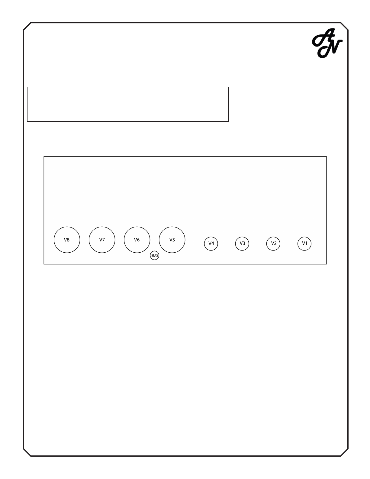
1. Inspect to make sure power and pre-amp tubes are intact and snuggly seated in their sockets
2. Make certain a speaker (load) is plugged into the correct speaker input jack on the back of the amplier.
Failure to have a speaker connected to the amp will result in damage to the output tubes. Your amplier is
supplied with multiple speaker inputs for various impedances; select the one closest to or transition your
speaker(s) impedance.
3. Install cable into footswitch and then connect into rear panel input marked FOOTSWITCH
4. Install instrument cable from guitar into front panel INPUT
5. Be sure both POWER and STANDBY switches are in DOWN position
6. Install power cord to amplier (AC POWER IN) and to AC power source
7. POWER UP amplier by:
1. ipping POWER switch UP. WAIT at least 1 minute for tubes to heat up
2. Flip STANDBY switch UP, amplier will now operate
8. The amplier is now fully on and ready to use. Feel free to adjust all controls as you see t
TO PUT AMP IN STANDBY MODE - Simply ip the STANDBY switch DOWN
TO PUT AMP IN PLAY MODE - Simply ip the STANDBY switch UP
TO TURN AMP OFF - Flip the STANDBY switch DOWN. We then recommend (as a kindness to the output
tubes) waiting at least 1 minute before ipping POWER switch DOWN hence fully shutting the amp down.
3

Front Panel Functions
Input Jack: High impedance input to the amplier. Plug in your instrument here.
Treble: Adjusts the high frequency response. In the full counter-clockwise position, high frequencies
are bypassed to ground. In the full clockwise position, high frequencies are increased.
Middle: Adjusts the mid-range response. In the full counter-clockwise position, the tone will be
somewhat “scooped” of mid-range response, emphasizing the highs and lows. In the full clockwise
position, mid-range frequencies are increased.
Bass: Adjusts the bass response. In the full counter-clockwise position, low frequencies are cut. In
addition, the response of the treble and mid-range controls is greatly reduced. In the full clockwise
position, low frequencies are increased.
Bright Switch: Boosts the treble frequency response.
Mid Switch: Boosts the mid range frequency response.
Deep Switch: Cuts high end frequency response as a low frequency contour switch.
Gain: Adjusts the gain of the ampliers clean channel. Keep in mind that the amount of gain set here
determines the signal level feeding the lead channel. Low gain settings of this control will require high-
er lead gain settings for the same amount of overdrive.
Master: Adjusts the overall output level of the amplier.
Drive: Adjusts the amount of gain of the overdrive channel.
Drive Level: Adjusts the overall volume level of the overdrive channel.
(CONTINUED ON TO NEXT PAGE)
4

Front Panel Functions (CONTINUED)
Overdrive Switch: Switches the amplier channel, sending the instrument signal through the overdrive
channel. To enable foot switch control of this function, this switch must be down.
PAB Switch: This switch bypasses the tone controls, increasing both level and mids. To enable foot
switch control of this function, switch must be down.
Reverb: The reverb control sets the level of reverb in the mix. The reverb eect is eliminated with this
control in the full counter clockwise position and increased when turned clockwise.
Contour Control: The contour control is similar to a ‘cut’ control. In the 12 o’clock position, the amps’
frequency response is at. Counterclockwise rotation reduces high end
response and increases low frequencies. Counterclockwise rotation decreases low end and increases
the high frequency response.
Stand-by Switch: Should be in the “down” or “stand-by” position when you apply power to the unit.
After turning the A/C mains on, place the switch in the “up” position to use the amplier. You may leave
the unit “powered up” and place this switch in the “stand-by” position to mute the output. Do not leave
the amp in standby for more than 30 minutes at a time.
Power Indicator Lamp: The replacement light bulb is a 6.3v A/C.
NOTE: All switches are ON in the “up” position
5

Rear Panel Functions
Mains: Connects the amplier to A/C power with included IEC power cord.
Fuse: See Fuse Chart page
Power Switch: Turns the A/C mains power on to the amplier.
Bias Test Points: See bias adjustment section
Speaker Output Jacks: There are 4 speaker output jacks, two 4ohm, one 8ohm and one 16ohm. You
should only use one speaker impedance at a time, or two 4ohm outputs are to be used to power two
8ohm cabinets.
**Never operate your amplier without a connected speaker load, and be sure to match the impedance
of your cabinet with the corresponding value on the amp.
Eects Loop: The eects loop of the Wonderland Overdrive is a passive signal access point. Any ef-
fects plugged into the loop will be run in series with the preamp and power amp.
Footswitch Jack: The footswitch connects with the included 7 pin locking cable. The functions of the
Wonderland Overdrive v2 include channel switching and preamp boost.
6

Fuse Chart
All Fuses are 3AG Type 250 Volt, SLO-BLO
Domestic Fuses:
2A – 22/35/40 Watt
3A - 50 Watt
3.2 - 100 Watt
Export 220, 230, 240 Fuses:
22/35/40 Watt
2A - 50 Watt
2.5A - 100 Watt
Tube Complement
V1- 12AX7, Input and Tone Stack Recovery
V2- 12AX7, Overdrive Stages
V3- 12AT7, Reverb Driver and Return
V4- 12AX7, Phase Inverter
Power Tubes:
22 Watt- V6 & V7 6V6GT, (Optional: V8 5AR4 Rectier)
40 Watt- V6, V7, V8, V9, 6V6GT
50 Watt- V6 & V7 6L6GC, V8 & V9 optional GZ34 rectiers tubes
100 Watt- V6, V7, V8, V9, 6L6GC-STR
Each ne production tube is tested and matched to our exacting specications. External bias
test points are located on the chassis near the output tube sockets. A digital multi-meter and
insulated screwdriver are required for the bias adjustment pot, which is in between V5 and V6.
7

Bias Adjustment Procedure
All of our amps are equipped with external bias test points and an external bias adjustment pot.
The adjustment pot is located in between the power tube sockets and should be adjusted using an
insulated at tip screwdriver.
- Power up unit connected to proper speaker load
- Do not have an instrument connected to the amp
- Take the amp o of standby and let it stabilize
- Set your multi meter to mV
- Connect the meter to corresponding black and red test points, black is ground
- Using an insulated screwdriver adjust the bias pot to get the proper mV reading
Tube types and bias level:
- 22w 6VGGT – 19-21mV per tube
- 50w 6L6GC – 33-35mmV per tube
- 50w EL-34-33-35mV per tube
- 100w 6L6GC – 66-70mV per pair
- 100w EL-34 – 66-70mV per pair
DO NOT set bias higher than recommended levels as it can lead to tube failure or damage to the
amplier.
WARNING: No user serviceable parts inside. If the amplier is blowing fuses or not operating
properly, please take it to a qualied technician for repair.
Use grounded A/C receptacle only
8

Servicing Warranty
Amplied Nation oers a 2-year non-transferrable warranty on
ampliers excluding: tubes, speakers, damage from tube failure, and
abuse/modication.
It is the customer’s responsibility to pay to ship the product to us, and if
it is determined the warranty doesn’t apply, the customer is responsible for
the return shipping.
If the product is a warranty repair, Amplied Nation will cover the
return shipping.
CONTACT US
This manual is a resource for some of your questions. Please contact us with any other questions or
comments that you may have. We look forward to hearing from you!
Phone: 781-499-2677
Email: Taylor Cox, CEO, Amplied Nation
Taylor@ampliednation.com
Alyson Cox, CCO, Amplied Nation
Website: www.ampliednation.com
Address: 120 Central Street, Suite 4, Hudson, Massachusetts 01749
9
This manual suits for next models
2
Table of contents