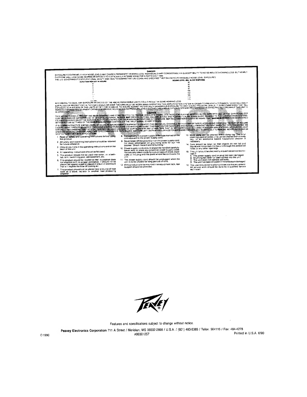
Amplifier Research 701R User manual

OWNERS
MANUAL
701R
MIXER

701R
™
MIXER

INTRODUCTION
The
system
you
have
purchased
is
a
very
portable
package
with
the
flexibility
of
mixers
twice
the
size
at
twice
the
price.
The
701R
™
features
seven
channels,
excellent
4-band
equalization,
rack-mount
versatility,
balanced
inputs,
and
balanced
outputs.
Rack-mountable
mixers
have
a
special
place
in
sound
rein¬
forcement
applications,
and
many
times
no
other
type
pro¬
duct
will
suffice.
The
701R
requires
a
very
low
profile,
vertical
mounting
space,
and
is
exceptionally
thin,
front
to
back.
These
dimensions
are
critical,
as
rack
space
is
usually
a
premium
consideration.
The
input
circuitry
has
tremendous
dynamic
range
and
will
handle
sound
reinforcement
applications
with
ease.
As
you
read
the
enclosed
literature,
please
try
to
learn
as
much
as
possible
about
the
product
so
your
job
of
sound
reproduction
will
be
easier
and
the
results
will
be
an
overall
improved
performance.
The
person
doing
sound
or
installing
sound
systems
is
actually
an
extension
of
the
performance
and
should
master
the
sound
equipment,
just
as
a
musician
masters
his/her
instrument.
INPUT
GAIN
CONTROL
(1)
The
Input
Gain
Control
of
the
701R
Mixer
utilizes
a
dual
con¬
trol
element
configuration
so
that
input
attenuation
and
gain
adjustment
occur
simultaneously.
This
arrangement
allows
the
vital
input
circuitry
to
handle
almost
any
input
voltage
from
low
level
mics
to
speaker
levels.
The
function
and
operational
requirements
of
this
input
gain
stage
are
conventional
and
should
present
no
operational
difficulty.
MONITOR
SEND
CONTROL
(2)
The
monitor
send
control
is
the
channel
mixing
element
for
determining
the
all
important
monitor
mix.
Signals
for
the
monitor
sends
are
obtained
right
after
the
input
preamp
and
before
the
channel
EQ.
These
are
referred
to
as
pre
monitor
sends,
i.e.
they
are
before
the
channel
equalization
and
chan¬
nel
level
controls.
This
makes
them
independent
of
these
con¬
trols
and
any
changes
made
to
the
EQ
or
channel
level
will
not
affect
the
monitor
system.
Having
the
monitor
send
with
pre-EQ
capability
is
absolutely
vital
to
avoid
feedback
of
the
monitor
system
when
EQ
and
normal
incremental
setting
variations
are
made
in
the
channel
fader
during
the
course
of
the
performance.
HIGH
FREQUENCY
EQ
(4)
This
control
determines
the
relative
boost
or
cut
of
the
highest
frequency
adjustment
on
this
console
and
features
a
15
dB
boost
or
cut
at
15
kHz.
This
control
operates
in
a
shelving
configuration
which
prevents
any
additional
gain
above
the
usable
audio
spectrum
from
causing
undesirable
hiss
and
instability.
The
zero
setting
indicates
a
flat
frequency
response
with
no
alteration
of
the
extreme
highs
and
clockwise
indicates
a
boost
while
counterclockwise
indicates
a
cut
or
a
dip
in
the
high
frequencies.
Usually
feedback
is
not
much
of
a
problem
at
very
high
frequencies,
but
the
control
is
very
important
for
giving
that
sibilant
sound
on
the
extreme
highs
and
on
the
s's
and
t’s
of
the
vocals.
HIGH
MID
FREQUENCY
EQ
(5)
This
control
determines
the
relative
boost
or
cut
of
the
upper
mid
or
lower
treble
frequencies
and
is
capable
of
15
dB
boost
or
cut
at
3
kHz.
A
balance
of
mid
range
frequencies
should
begin
with
a
flat
setting
of
zero
so
that
adjustments
may
be
made
with
a
cut
or
a
boost
of
this
control.
The
action
of
the
control
is
peak/notch
type
which
interfaces
with
the
adjacent
equalizers
in
a
smoother
manner
to
yield
optimum
summing
capability
of
the
channel
equalization.
Usually
a
minus
set¬
ting
of
this
control
is
desirable
to
eliminate
harshness
with
most
systems
and
control
feedback.
LOW
MID
FREQUENCY
EQ
(5)
This
control
is
operational
in
the
lower
mid
range
or
upper
bass
region
and
is
capable
of
15
dB
boost
or
cut
at
400
Hz.
This
EQ
control
exhibits
a
peak/notch
characteristic
which
operates
smoothly
with
the
adjacent
equalizer
controls
and
allows
proper
balancing
of
the
upper
bass
and
lower
mid
range
frequencies.
This
control
is
very
vital
for
controlling
the
mid
range
frequencies
of
the
human
voice
when
vocals
are
being
amplified.
(Most
vocals
require
a
slight
minus
setting
of
this
control.)
LOW
FREQUENCY
EQ
(6)
This
control
is
capable
of
15
dB
boost
or
cut
at
60
Hz
and
demonstrates
a
shelving
characteristic
so
that
excessive
lows
are
not
boosted
below
the
usable
range
of
typical
sound
rein¬
forcement.
The
shelving
action
of
this
circuit
has
proven
to
yield
much
more
satisfying
and
effective
equalization
characteristics
than
some
of
the
wide
open
EQ
circuits
claim¬
ing
20
to
25
dB
boost
and
cut.
Care
should
be
taken
with
the
low
frequency
control
not
to
over-boost
lows
on
any
particular
instrument
or
vocal
due
to
the
fact
that
tremendous
amounts
of
headroom
will
be
used
up
and
a
general
muddiness
will
be
apparent
in
the
sound
system
reproduction.
Woofers
may
also
be
blown
much
more
easily
with
extreme
low
frequency
boost.
EFFECTS
SEND
CONTROL
(7)
This
effects
control
is
post
and
is
effected
by
the
equaliza¬
tion
of
each
channel
and
its
level
is
also
effected
by
the
chan¬
nel
level
control.
NOTE:
This
action
is
totally
opposite
from
the
monitor
send
controls
on
each
channel
which
are
pre
and
unaffected
by
other
features
on
the
channel.
When
the
ef¬
fects
send
control
is
activated
on
any
particular
channel,
a
signal
is
sent
through
the
master
effects
level
control
and
ap¬
pears
at
the
effects
output
on
the
rear
panel.
This
output
may
be
patched
into
many
various
effects
devices.
(See
effects
patch
diagrams.)
NOTE:
The
internal
reverb
drive
receives
its
signal
from
the
effects
send
control
also
and
a
signal
is
then
sent
to
the
master
reverb
control
in
the
master
section
in
order
for
the
internal
reverberation
system
to
function.
When
operating
an
outboard
effects
device
and
the
internal
reverb
system
simultaneously,
the
channel
send
control
on
the
ef¬
fects
mix
must
be
optimized
for
the
amount
of
both
effects
on
a
particular
channel.
PAN
CONTROL
(8)
This
control
is
most
often
used
to
assign
certain
channels
to
one
or
both
subs.
The
action
is
conventional
and
clockwise
rotation
assigns
to
sub
“B”
while
counterclockwise
rotation
assigns
to
sub
“A”.
A
setting
of
12:00
places
the
channel
equally
in
both
subs.
NOTE:
When
recording,
this
control
may
be
used
for
stereo
imaging
(left,
right,
or
both).
CHANNEL
LEVEL
CONTROL
(9)
The
channel
level
is
the
output
control
that
determines
the
mix
of
the
various
channels
into
the
master
mix.
This
control
should
be
operated
near
the
zero
indication
of
unity
gain
whenever
possible
and
the
input
gain
control
should
be
ad¬
justed
accordingly
for
each
instrument
or
vocal,
etc.
NOTE:
Above
the
zero
point
on
the
channel
level
slider
there
is
14
dB
of
gain
as
you
increase
to
the
upper
limit
of
the
level
con¬
trol.
It
is
virtually
impossible
to
have
too
much
gain
during
typical
sound
reinforcement
situations
and
when
a
low
gain
situation
presents
itself
it
is
nice
to
be
able
to
increase
the
channel
gain
by
14
dB
with
the
level
control
and
possibly
avoid
having
to
readjust
input
gain
sensitivity.
NOTE:
Operation
above
“0”
increases
system
noise.
Operation
below
“0”
decreases
system
noise
but
at
the
sacrifice
of
system
headroom.

MASTER
SECTION
—
FRONT
PANEL
As
the
name
implies,
the
master
section
of
the
701R
Mixer
contains
all
of
the
controls
for
the
respective
mixing
busses
and
supplementary
controls
to
allow
other
special
functions
to
be
achieved.
The
master
level
controls
should
be
set
in
such
a
manner
that
they
are
close
to
the
center
of
their
travel
(0
dB)
to
take
advantage
of
the
maximum
control
action.
It
is
poor
practice
to
set
up
the
input
channels
at
too
high
a
level
which
will
require
the
user
to
run
the
main
levels
at
a
low
set¬
ting
to
achieve
the
desired
result.
Operation
in
this
manner
will
cause
the
operator
to
lose
his
“range"
of
the
control
ac¬
tion
with
all
the
gain
located
in
one
element
while
the
other
is
in
the
infinity
position.
This
manner
of
operation
also
tends
to
create
headroom
problems.
Best
practice
calls
for
most
con¬
trols
to
be
operated
near
the
middle
of
their
operating
range
to
allow
mixing
control
margins.
Remember
that
while
mix¬
ing
it
is
important
to
allow
yourself
adequate
margins
within
which
to
operate.
By
using
any
of
the
controls
in
their
extreme
positions,
you
have
effectively
reduced
your
operational
latitude.
These
master
controls
allow
the
operator
complete
flexibility
of
functions
and
should
allow
almost
any
mixing
situation
to
be
handled.
As
with
any
reasonably
complex
system,
ex¬
perience
and
operator
knowledge
of
the
equipment
are
essen¬
tial
for
satisfactory
performance.
The
mixer,
like
the
musician’s
instrument,
should
be
practiced
on
and
learned.
To
properly
operate
a
mixer
during
a
performance
requires
thorough
knowledge
and
trained
reflexes
to
allow
proper
responses
under
the
stress
of
demanding
and
sometimes
sudden
situations.
Please
note
that
the
master
level
controls
have
a
0
dB
indica¬
tion.
Operating
within
these
ranges
will
assure
the
best
com¬
bination
of
signal
to
noise
ratio
and
headroom.
SUB
MASTERS
(A
&
B)
(10)
The
subs
(A
&
B)
are
the
main
output
level
controls
and
regulate
the
signal
levels
being
supplied
to
the
output
jacks
on
the
rear
panel
Again,
under
normal
usage,
these
controls
should
be
operated
near
the
0
dB
range
to
allow
optimum
performance.
The
unique
circuitry
of
the
701R
Mixer
derives
a
signal
which
is
the
sum
of
the
A
and
B
outputs
in
order
to
make
possible
operation
of
the
A
and
B
outputs
as
submasters
to
the
sum.
As
with
the
sub
A
and
B
controls,
the
sum
should
be
operated
close
to
its
middle
(0
dB)
range.
MASTER
MONITOR
CONTROL
(11)
The
master
monitor
control
is
located
just
above
the
sum
master
control.
Operation
of
this
control
is
similar
to
that
of
any
rotary
gain
control
on
the
mixer
and
should
be
set
in
con¬
junction
with
the
respective
individual
channel
monitor
send
controls
to
achieve
operation
somewhere
within
the
middle
rotation
of
the
master
control.
The
action
of
this
control
is
con¬
ventional
and
should
present
no
problem.
The
output
signal
from
the
master
monitor
is
available
from
the
output
connec¬
tors
on
the
rear
panel.
Again,
under
normal
usage,
these
con¬
trols
should
also
be
operated
near
the
center
of
their
range
to
allow
optimum
performance.
EFFECTS
RETURN
CONTROL
(12)
The
effects
return
control
may
be
considered
an
auxiliary
in¬
put
channel
with
a
high
impedance
input
and
has
been
designed
to
accept
a
wide
range
of
audio
signals.
This
ef¬
fects
control
is
coupled
to
the
effects
pan,
which
then
feeds
into
the
Sub
A
and
Sub
B
mixing
busses.
EFFECTS
PAN
CONTROL
(13)
The
effects
pan
control
determines
the
relative
balance
from
the
effects
level
control
blended
into
the
sub
mixing
busses.
EFFECTS
TO
MONITOR
CONTROL
(14)
The
effects
to
monitor
control
enables
signals
from
the
effects
return
input
to
be
mixed
back
into
the
monitor
mixing
bus.
This
unique
feature
enables
external
effects
such
as
echo
units,
flangers,
delay
lines,
etc.,
to
be
blended
back
into
the
monitor
output
signal
if
desired.
REVERB
RETURN
CONTROL
(15)
The
reverb
return
control
determines
the
amount
of
delay
(reverb)
signal
blended
back
into
the
subs.
REVERB
PAN
(16)
The
reverb
pan
control
determines
the
relative
balance
from
the
reverb
level
control
blended
into
the
sub
mixing
busses.
REVERB
TO
MONITOR
CONTROL
(17)
This
unique
circuit
of
the
701R
Mixer
allows
mixing
of
reverberation
signal
back
into
the
monitor
mixing
bus
for
those
who
do
not
prefer
a
“dry”
monitor
sound.
(NOTE:
Feedback
may
be
more
pronounced
with
reverb
on
the
monitors.)
EFFECTS
MASTER
CONTROL
(18)
The
effects
master
control
is
the
final
control
element
deter¬
mining
the
output
level
from
the
effects
send
jack
on
the
rear
panel,
as
well
as
the
amount
of
reverb
drive
delivered
to
the
internal
reverberation
system.
Please
note
that
no
reverbera¬
tion
effect
may
be
achieved
unless
the
individual
channel
ef¬
fects
send
controls
and
the
effects
level
control
are
adjusted
properly.
STEREO
OUT
(19)
Controls
the
level
appearing
at
the
stereo
output
jack
at
the
rear
panel.
(See
back
panel)
LED
OUTPUT
LEVEL
INDICATION
(20)
NOTE:
The
two,
10-segment
LED
ladders
on
the
front
panel
are
extremely
important
visual
“tools”
and
their
operation
must
be
understood
to
achieve
maximum
benefits
from
this
mixing
system.
The
two
LED
displays
have
a
unique
“switching”
system
allowing
each
ladder
a
“dual”
function.
The
switch
located
to
the
left
of
the
LED
lad¬
ders
enables
the
operator
to
choose
either
the
Sum
(switch
in
the
“in”
position)
or
sub
A
(switch
in
the
“out”
position)
output
levels
to
be
displayed
on
the
left
LED
ladder.
The
switch
to
the
right
of
the
LED
ladder
allows
a
choice
of
Monitor
(switch
in
the
“in”
position)
or
sub
B
(switch
in
the
“out”
posi¬
tion)
output
levels
on
the
right
LED
ladder.
The
LED
ladders
feature
an
extremely
effective
“warning
system”
for
all
of
the
above
mentioned
functions.
Should
the
LED
ladders
reach
the
6
dBV
LED
(top
of
the
ladder
reading),
the
remaining
LEDs
automatically
“shut-down”
giving
the
operator
an
instant
visual
indication
that
the
possibility
of
clip¬
ping
might
be
present.
NOTE:
Under
normal
operating
con¬
ditions,
the
channel
levels
and
master
controls
for
Sub
A,
Sub
B,
Sum,
and
Monitor
should
all
be
operated
near
their
center
positions
(0
dB
indicated).
This
type
of
opera¬
tion
will
ensure
that
the
possibility
of
clipping
(overload)
is
at
a
minimum.
Each
channel
of
the
701R
Mixer
has
a
10
dB
LED
level
in¬
dicator.
This
red
LED
serves
as
a
warning
device
for
the
operator
indicating
that
any
particular
channel
has
reached
10
dBV
(3V
RMS),
and
the
possibility
of
“clipping”
could
occur.
Actual
“clipping"
occurs
at
18
dBV,
so
when
the
LED
flashes,
8
dB
of
headroom
is
left.
If
this
LED
stays
lit
con¬
tinuously,
the
operator
should
reduce
the
input
gain
control
on
that
channel.
Occasional
flashing
on
“peaks"
can
be
con¬
sidered
normal.
POWER
SWITCH/PILOT
LED
(21)
The
power
switch
is
of
the
simple
2-position
“rocker”
type
with
the
pilot
LED
immediately
below
it.
Operation
of
this
switch
is
conventional
and
should
present
no
problems
in
operation.
The
“on”
position
will
be
indicated
when
the
LED
pilot
light
glows,
signifying
power
is
being
delivered
to
the
mix¬
er
circuitry.

REAR
PANEL
INPUT
SECTION
The
rear
panel
of
the
701R
Mixer
contains
all
the
interface
connection
to
and
from
the
electronic
circuitry.
The
versatili¬
ty
offered
by
these
connections
is
unmatched
by
any
com¬
peting
unit
and
a
thorough
understanding
of
the
various
features
is
essential
in
order
to
fully
realize
the
performance
and
versatility
of
this
unit.
Each
channel
features
both
balanced
(symmetrical)
low
im¬
pedance
(600
ohms)
as
well
as
high
impedance
(50K
ohms)
unbalanced
inputs,
Each
of
these
inputs
feature
extremely
wide
dynamic
range
and
are
fully
transient-protected
to
en¬
sure
durability
under
road
conditions.
While
these
inputs
are
intended
primarily
for
microphones,
they
will
also
work
well
for
many
other
types
of
program
sources.
OUT/IN
JACK
(22)
The
701R
features
a
“stereo”
out/in
jack
on
each
channel
to
facilitate
the
use
of
direct
outputs/inputs
from
the
preamps
for
“patching”
various
auxiliary
units
(chorus,
flanging,
tape/digital/analog
delays,
equalizers,
etc.)
“inline.”
To
utilize
this
unique
system,
a
stereo
plug
(ring/tip/sleeve)
to
a
“Y”
chord
must
be
used.
The
“tip”
portion
of
the
W'
stereo
jack
serves
as
the
channel
send
(output)
while
the
“ring”
portion
will
return
the
processed
signal
to
the
channel.
The
“sleeve”
portion
serves
as
the
ground.
Since
this
is
a
stereo
jack
configuration,
the
first
“click”
on
the
jack
may
be
used
as
a
“pre-EQ”
output
with
a
mono
Vi"
plug
if
desired.
This
first
“click”
will
not
disturb
the
signal
flow
to
the
remainder
of
the
channel
as
it
is
fed
into
the
master
section.
NOTE:
IF
THE
SECOND
CLICK
OF
THE
OUT/IN
JACK
IS
UTILIZED
WITHOUT
RETURNING
ANY
SIGNAL
TO
THE
CHANNEL
FROM
AN
EFFECTS
DEVICE
THE
REMAIN¬
ING
PREAMP
FUNCTIONS
WILL
BE
DISABLED.
REAR
PANEL
REAR
PANEL
MASTER
PATCH
SECTION
SUBS
(A
&
B),
MONITOR,
AND
SUM
OUTPUTS
(23)
Each
line
out
features
a
phone
jack
as
well
as
a
balanced
XLR
output
to
enable
maximum
patching
flexibility.
These
line
amplifiers
are
capable
of
providing
more
than
8V
RMS
out¬
put,
and
are
fully
transient
and
short
circuit
protected
for
max¬
imum
field
reliability.
The
output
level
presented
by
these
jacks
is
controlled
by
the
settings
of
the
various
master
level
con¬
trols
on
the
front
panel.
EFFECTS
OUTPUT
(24)
The
effects
output
presents
the
signal
from
the
effects
mix¬
ing
bus.
This
jack
is
of
a
unique
“two-position”
type
with
the
first
position
being
the
low
level
output
and
the
second
posi¬
tion
being
the
high
level
output.
This
unique
arrangement
enables
use
of
this
mixer
with
either
line
level
or
instrument
level
effects
device
depending
on
which
“click”
of
the
jack
is
used.
The
overall
output
level
from
the
effects
jack
is
deter¬
mined
by
the
setting
of
the
master
effects
level
control
on
the
front
panel.
REVERB
FOOTSWITCH
(25)
To
facilitate
remote
control
of
the
reverberation
function,
we
have
included
a
remote
control
footswitch
jack.
Any
standard,
single
pole
footswitch
may
be
used
to
remotely
defeat
the
reverb
function.
Please
note
that
this
switch
disables
the
reverb
system
only
and
has
no
effect
whatsoever
on
the
ef¬
fects
system.
EFFECTS
RETURN
(26)
The
effects
return
input
on
the
rear
panel
may
be
considered
an
auxiliary
channel
featuring
its
own
level
and
panning
con¬
trols
located
on
the
front
panel.
This
effects
return
is
capable
of
handling
a
wide
range
of
input
signals
and
is
a
very
high

impedance
type
(220K
ohms).
The
effects
return
system
feeds
into
both
main
mixing
busses
and
is
intended
for
use
when
returning
signals
from
external
devices
to
be
mixed
into
the
main
mixing
busses.
STEREO
OUT
JACK
(27)
The
701R
Mixer
is
supplied
with
a
highly
usable
stereo
out¬
put
jack
for
connection
to
recording
decks
or
other
outboard
equipment.
Musicians/sound
personnel
will
find
this
line-level
stereo
output
perfect
for
recording
live
performances
and/or
rehearsals.
AUXILIARY
INPUTS
(28)
The
auxiliary
inputs
are
line
level
access
points
to
the
five
internal
mixing
busses.
They
are
medium
impedance
type
(33K
ohms)
and
are
provided
to
allow
parallel
mixers
or
for
any
other
purpose
that
requires
direct
signal
injection
into
the
internal
mixing
busses.
LINE
CORD
(29)
For
your
safety,
we
have
incorporated
a
3-wire
line
(mains)
cable
with
proper
grounding
facilities.
WARNING:
IT
IS
NOT
ADVISABLE
UNDER
ANY
CIR¬
CUMSTANCES
TO
REMOVE
THE
GROUND
PIN.
IF
IT
IS
NECESSARY
TO
USE
THE
AMP
IN
A
2-PIN
PLUG
SYSTEM
WITHOUT
PROPER
GROUNDING
FACILITIES,
SUITABLE
GROUNDING
ADAPTORS
SHOULD
BE
USED.
MUCH
LESS
NOISE
AND
GREATLY
REDUCED
SHOCK
HAZARD
EXISTS
WHEN
THE
UNIT
IS
OPERATED
WITH
THE
PROPER
GROUNDED
RECEPTACLES.
LINE
INPUTS
(RCA)
(30)
Channels
six
and
seven
function
normally
with
microphones
or
line
level
signals
but
also
have
additional
(RCA)
inputs.
The
“in”
position
of
the
push
switch
which
is
located
in
the
master
section
allows
an
input
signal
to
be
patched
into
6
and
7
from
the
line
inputs
at
the
rear
panel.
With
the
switch
in
the
“out”
position,
channels
6
and
7
can
be
used
with
the
normal
mic
or
line
inputs.
(Please
check
the
specifications
of
any
device
being
patched
in.)
SPECIFICATIONS
SUMMARY
OF
FUNCTIONS
7
ch
in;
Sub
A
&
B
out;
sum
out;
1
pre
mon.
out,
1
post
effect
(high/low
level)
out;
stereo
out;
4
band
EQ,
pan,
+10
dBV
LED
each
channel
MASTER
Effects
&
reverb
return
with
pan,
effects
&
reverb
to
monitor;
dual/switchable
LED
ladders;
stereo
(RIAA)
phono
inputs
(switched
to
ch.
6
&
7)
INPUTS,
EACH
CHANNEL
1
low
Z
balanced
microphone;
1
high
Z
unbalanced
line;
1
high
Z
unbalanced
(stereo
ring)
pre
return
INPUTS,
MASTER
1
high
Z
unbalanced
auxiliary
each
for
Sub
A,
Sub
B,
monitor,
sum,
and
effects;
1
high
Z
unbalanced
effects
return,
stereo
(RIAA)
phono
inputs
OUTPUTS,
EACH
CHANNEL
1
low
Z
unbalanced
(stereo
tip)
pre
send
OUTPUTS,
MASTER
1
low
Z
transformer
balanced
line
&
1
low
Z
unbalanced
line
each
for
Sub
A,
Sub
B,
monitor,
and
sum;
1
unbalanced
(stereo
jack)
stereo
out;
Rev
F.S.;
1
low
Z
unbalanced
(high/low
level)
effects
CHANNEL
MICROPHONE
INPUTS
Mic
Impedance:
Low
Z
600
ohms
balanced
Nominal
Input
Level:
-26
dBM,
40
mV
RMS
Minimum
Input
Level:
-42
dBM,
6
mV
RMS
Maximum
Input
Level:
+8
dBM,
2
volts
RMS
CHANNEL
LINE
(HIGH
Z
MIC)
INPUTS
Line
Impedance:
Hi
Z
50K
ohms
unbalanced
Nominal
Input
Level:
-14
dBV,
200
mV
RMS
Minimum
Input
Level:
-30
dBV,
30
mV
RMS
Maximum
Input
Level:
+30
dBV,
30
volts
RMS
CHANNEL
RETURNS
AND
AUXILIARY
INPUTS
Line
Impedance:
Hi
Z
33K
ohms
unbalanced
Designed
Input
Level:
0
dBV,
1
volt
RMS
STEREO
LINE
INPUTS
(RCA)
Line
Impedance:
50K
ohms
Nominal
Input
Level:
-14
dBV,
200
mV
RMS
Minimum
Input
Level:
-30
dBV,
30
mV
RMS
Maxinum
Input
Level:
+18
dBV,
8V
RMS
EFFECTS
RETURN
INPUT
Line
Impedance:
Hi
Z
100K
ohms
unbalanced
Nominal
Input
Level:
0
dBV,
IV
RMS
Minimum
Input
Level:
-14
dBV,
0.2V
RMS
Maximum
Input
Level:
+6
dBV,
2V
RMS
SUB
A,
SUB
B,
MONITOR
&
SUM
BALANCED
OUTPUTS
Load
Impedance:
600
ohms
or
greater
Nominal
Output:
0
dBV,
IV
RMS
Maximum
Output:
+18
dBV,
8V
RMS
into
50K
ohms
load
+16
dBM,
5V
RMS
into
600
ohms
load
SUB
A,
SUB
B,
MONITOR,
SUM
&
EFFECTS
(HIGH
LEVEL)
UNBALANCED
OUTPUTS
Load
Impedance:
600
ohms
or
greater
Nominal
Output:
0
dBV,
1
V
RMS
Maximum
Output;
+18
dBV,
8V
RMS
into
50K
ohms
load
+16
dBM,
5V
RMS
into
600
ohms
load
EFFECTS
(LOW
LEVEL)
UNBALANCED
OUTPUT
Load
Impedance:
10K
ohms
or
greater
Nominal
Output:
-12
dBV,
0.25V
RMs
Maximum
Output:
+6
dBV,
2V
RMS
The
following
specs
measured
with
a
nominal
input
gain
setting
of
+14
dB
all
channels,
all
levels
set
at
0
dB,
all
EQ
set
flat,
all
Low
Z
inputs
terminated
with
600
ohms,
all
High
Z
inputs
and
all
outputs
terminated
with
47K
ohms
Frequency
Response
(Any
in/out
combination
with
IV
RMS
output)
+0,
-2
dB,
20
Hz
to
30
kHz
System
Hum
&
Noise
-84
dBV
(High
Z
line
inputs)
(All
channels
on)
-80
dBV
(Low
Z
mic
inputs)
Equivalent
Input
Noise
(20
Hz
-
20
kHz,
250
ohms)
-126
dBV
Overall
Distortion
(Any
in/out
combination,
20
Hz
-
20
kHz
IV
RMS)
Less
than
.05%
THD,
TYP
below
.01%
Equalization
+15
dB
60
Hz
&
15
kHz,
shelving
+15
dB
400
Hz
&
3
kHz,
peak/notch
Crosstalk
Greater
than
50
dB
1
kHz
Maximum
Available
Gain
+14
dB
Sum
Control
+14
dB
Sub
Control
+14
dB
Channel
Control
+30
dB
Input
Control
+14
dB
Balanced
Input
Circuit
+86
dB
Total
LED
Readout
Range
-21
to
+6
dBV
(Switchable
Sub
A/Sum,
Sub
B/Monitor)
Channel
Status
Indicator
LED
Calibration
+10
dBV
(Red)
Power
Requirements
120V
AC,
60
Hz,
20
Watts
(Domestic)

THIS
LIMITED
WARRANTY
VALID
ONLY
WHEN
PURCHASED
AND
REGISTERED
IN
THE
UNITED
STATES
OR
CANADA.
ALL
EXPORTED
PRODUCTS
ARE
SUBJECT
TO
WAHHANTY
AND
SERVICES
TO
BE
SPECIFIED
AND
PROVIDED
BY
THE
AUTHORIZED
DISTRIBUTOR
FOR
EACH
COUNTRY.
Ces
clauses
de
garantle
ne
sort
ratable*
qu’aux
Etats-Unlset
au
Canada.
Dan*
tous
las
autre*
pays,
las
clauses
da
garantie
at
de
maintenance
sonl
flxees
par
le
distributee
national
at
assuree
par
lul
seion
la
legislation
en
vfgueur.
Dta.se
Garantle
1st
nur
In
den
USA
and
Kanada
guttig.
All*
Export-Produkte
slnd
der
Garantie
und
dem
Service
de*
Importeurs
des
Jewelllgen
Landes
unterworlen.
Esta
garantia
es
vailda
solamente
cuando
el
producto
escomprado
en
E.U.
continentaleso
en
Canada.
Todos
los
produclos
que
seen
compradosen
el
exlranjero,
estan
sujetos
a
las
garantlas
y
servleio
que
cada
dlstrtbuldor
aulorlzado
determine
y
ofrezca
en
los
dilerentes
palses.
ONE-YEAR
LIMITED
WARRANTY/REMEDY
PEAVEY
ELECTRONICS
CORPORATION
<
“PEAVEY")
warrants
this
product,
EXCEPT
tor
covers,
footswitches,
patchcords,
tubes
and
meters,
to
be
tree
from
defects
in
material
and
workmanship
for
a
period
of
one
(1)
year
from
date
of
purchase,
PROVIDED,
however
that
this
limited
warranty
is
extended
only
to
the
original
retail
purchaser
and
is
subject
to
the
conditions,
exclusions
and
limitations
hereinafter
set
forth:
PEAVEY
90-DAY
LIMITED
WARRANTY
ON
TUBES
AND
METERS
If
this
product
contains
tubes
or
meters,
Peavey
warrants
the
tubes
or
meters
contained
in
the
product
to
be
free
from
defects
in
material
and
workmanship
lor
a
period
of
ninety
(90)
days
from
date
of
purchase;
PROVIDED,
however,
that
this
limited
warranty
is
extended
only
to
the
original
retail
purchaser
and
is
also
subject
to
the
conditions,
exclusions
and
limitations
hereinafter
set
forth.
CONDITIONS,
EXCLUSIONS
AND
LIMITATIONS
OF
LIMITED
WARRANTIES
These
limited
warranties
shall
be
void
and
of
no
effect
if:
a.
The
first
purchase
of
the
product
is
for
the
purpose
of
resale;
or
b.
The
original
retail
purchase
is
not
made
from
an
AUTHORIZED
PEAVEY
DEALER;
or
c.
The
product
has
been
damaged
by
accident
or
unreasonable
use,
neglect,
improper
service
or
maintenance,
or
other
causes
not
arising
out
of
defects
in
material
or
workmanship;
or
d.
The
serial
number
affixed
to
the
product
is
altered,
defaced
or
removed.
In
Ihe
event
of
a
defect
in
material
and/or
workmanship
covered
by
this
limited
warranty,
Peavey
will:
a.
In
the
case
of
tubes
or
meters,
replace
the
defective
component
without
charge;
b.
In
other
covered
cases
(i.e.,
cases
involving
anything
other
than
covers,
footswitches,
patchcords,
tubes
or
meters),
repair
the
detect
in
material
or
workmanship
or
replace
the
product,
at
Peavey's
option;
and
provided,
however,
that,
in
any
case,
all
costs
of
shipping,
if
necessary,
are
paid
by
you,
the
purchaser.
THE
WARRANTY
REGISTRATION
CARDSHOULD
BE
ACCURATELY
COMPLETED
AND
MAILEDTO
AND
RECEIVED
BY
PEAVEY
WITHIN
FOURTEEN
(14)
DAYS
FROM
THE
DATE
OF
YOUR
PURCHASE.
In
order
to
obtain
service
under
these
warranties,
you
must:
a.
Bring
the
defective
item
to
any
AUTHORIZED
PEAVEY
DEALER
or
AUTHORIZED
PEAVEY
SERVICE
CENTER
and
present
therewith
the
ORIGINAL
PROOF
OF
PURCHASE
supplied
to
you
by
the
AUTHORIZED
PEAVEY
DEALER
in
connection
with
your
purchase
from
him
of
this
product.
If
fhe
DEALER
or
SERVICE
CENTER
is
unable
to
provide
the
necessary
warranty
service
you
will
be
directed
to
the
nearest
other
PEAVEY
AUTHORIZED
DEALER
or
AUTHORIZED
PEAVEY
SERVICE
CENTER
which
can
provide
such
service.
OR
b.
Ship
the
defective
item,
prepaid,
to;
PEAVEY
ELECTRONICS
CORPORATION
International
Service
Center
Highway
80
East
MERIDIAN.
MS
39301
including
therewith
a
complete,
detailed
description
of
the
problem,
together
with
a
legible
copy
of
the
original
PROOF
OF
PURCHASE
and
a
complete
return
address.
Upon
Peavey’s
receipt
of
these
items:
If
the
defect
is
remedial
under
these
limited
warranties
and
the
other
terms
and
conditions
expressed
herein
have
been
complied
with,
Peavey
will
provide
the
necessary
warranty
service
to
repair
or
replace
the
product
and
will
return
it,
FREIGHT
COLLECT,
to
you,
the
purchaser.
Peavey’s
liability
to
the
purchaser
for
damages
from
any
cause
whatsoever
and
regardless
of
the
form
of
action,
including
negligence,
is
limited
to
the
actual
damages
up
to
the
greater
of
$500.00
or
an
amount
equal
to
the
purchase
price
of
the
product
that
caused
the
damage
or
that
is
the
subject
of
or
is
directly
related
to
the
cause
of
action.
Such
purchase
price
will
be
that
in
effect
for
the
specific
product
when
the
cause
of
action
arose.
This
limitation
of
liability
will
not
apply
to
claims
for
personal
injury
or
damage
to
real
property
or
tangible
personal
property
allegedly
caused
by
Peavey’s
negligence.
Peavey
does
not
assume
liability
for
personal
injury
or
property
damage
arising
out
of
or
caused
by
a
non-Peavey
alteration
or
attachment,
nor
does
Peavey
assume
any
responsibility
lor
damage
lo
interconnected
non-Peavey
equipment
that
may
result
from
the
normal
functioning
and
maintenance
of
the
Peavey
equipment.
UNDER
NO
CIRCUMSTANCES
WILL
PEAVEY
BE
LIABLE
FOR
ANY
LOST
PROFITS,
LOST
SAVINGS.
ANY
INCIDENTAL
DAMAGES
OR
ANY
CONSEQUENTIAL
DAMAGES
ARISING
OUT
OF
THE
USE
OR
INABILITY
TO
USE
THE
PRODUCT,
EVEN
IF
PEAVEY
HAS
BEEN
ADVISED
OF
THE
POSSIBILITY
OF
SUCH
DAMAGES.
THESE
LIMITED
WARRANTI
ES
ARE
IN
LIEU
OF
ANY
AND
ALL
WARRANTIES,
EXPRESS
OR
IMPLIED.
INCLUDING,
BUT
NOT
LIMITED
TO,
THE
IMPLIED
WARRANTIES
OF
MERCHANTABILITY
AND
FITNESS
FOR
A
PARTICULAR
USE;
PROVIDED,
HOWEVER,
THAT
IF
THE
OTHER
TERMS
AND
CONDITIONS
NECESSARY
TO
THE
EXISTENCE
OF
THE
EXPRESS.
LIMITED
WARRANTIES,
AS
HEREINABOVE
STATED.
HAVE
BEEN
COMPLIED
WITH,
IMPLIED
WARRANTIES
ARE
NOT
DISCLAIMED
DURING
THE
APPLICABLE
ONE-YEAR
OR
NINETY-DAY
PERIOD
FROM
DATE
OF
PURCHASE
OF
THIS
PRODUCT.
SOME
STATES
DO
NOT
ALLOW
LIMITATION
ON
HOW
LONG
AN
IMPLIED
WARRANTY
LASTS,
OR
THE
EXCLUSION
OR
LIMITATION
OF
INCIDENTAL
OR
CONSEQUENTIAL
DAMAGES,
SO
THE
ABOVE
LIMITATIONS
OR
EXCLUSIONS
MAY
NOT
APPLY
TO
YOU.
THESE
LIMITED
WARRANTIES
GIVE
YOU
SPECIFIC
LEGAL
RIGHTS,
AND
YOU
MAY
ALSO
HAVE
OTHER
RIGHTS
WHICH
MAY
VARY
FROM
STATE
TO
STATE
THESE
LIMITED
WARRANTIES
ARE
THE
ONLY
EXPRESS
WARRANTIES
ON
THIS
PROOUCT,
AND
NO
OTHER
STATEMENT,
REPRESENTATION,
WARRANTY
OR
AGREEMENT
BY
ANY
PERSON
SHALL
BE
VALID
OR
BINDING
UPON
PEAVEY.
In
the
event
of
any
modification
or
disclaimer
of
express
or
implied
warranties,
orany
limitation
of
remedies,
contained
herein
conflicts
with
applicable
law,
then
such
modification,
disclaimer
or
limitation,
as
the
case
may
be.
Shall
be
deemed
to
be
modified
to
the
extent
necessary
to
comply
with
such
law.
Your
remedies
for
breach
of
these
warranties
are
limited
to
those
remedies
provided
herein
and
Peavey
Electronics
Corporation
gives
this
limited
warranty
only
with
respect
to
equipment
purchased
in
the
United
States
of
America,
INSTRUCTIONS
-
WARRANTY
REGISTRATION
CARD
1.
Mail
the
completed
WARRANTY
REGISTRATION
CARD
to:
PEAVEY
ELECTRONICS
CORPORATION
POST
OFFICE
BOX
2898
MERIDIAN,
MISSISSIPPI
39302-2896
a.
Keep
the
PROOF
OF
PURCHASE.
In
the
event
warranty
service
is
required
during
the
warranty
period,
you
will
need
this
document.
There
will
be
no
identification
card
Issued
by
Peavey
Electronics
Corporation.
2.
IMPORTANCE
OF
WARRANTY
REGISTRATION
CARDS
AND
NOTIFICATION
OF
CHANGES
OF
ADDRESS:
a.
Completion
and
mailing
of
WARRANTY
REGISTRATION
CARDS
—
Should
notification
become
necessary
for
any
condition
that
may
require
correction,
the
REGISTRATION
CARD
will
help
ensure
that
you
are
contacted
and
properly
notified.
b.
Notice
of
address
changes
—
If
you
move
from
the
address
shown
on
the
WARRANTY
REGISTRATION
CARD,
you
should
notify
Peavey
of
the
change
of
address
so
as
to
facilitate
your
receipt
of
any
bulletins
or
other
forms
of
notification
which
may
become
necessary
in
connection
with
any
condition
that
may
require
dissemination
of
information
or
correction.
3.
You
may
contact
Peavey
directly
by
telephoning
(601)
483-5365.
4.
Please
have
the
PeavBy
product
name
and
serial
number
available
when
communicating
with
Peavey
Customer
Service.

DANGER
INDIVIDUALS
VARY
CONSIOI
A
SUFFICIENT
TIME
HAS
SPECIFIED
~HE
FOLLOW
ACCORDING
TO
OSHA
ANY
EXPOSURE
EAR
PLUGS
OR
PROTECTORS
in
the
EAR
CANALS
OR
OVER
the
EARS
MUSI
L
-
EVELS
r
jS
RECOM
PCRSCn'
I
XP4Mhfc0^^^rt^^^*^^*E*EA^^BL^^^PCIOUE^Nii'Il'Ci^^®LN^P^E
,
^L^€
;
EEVEL5^^pl^|?
:
’
.lil5»A*A^Wfc*CA
T
|^IAl^YST£M6F
HI
AR.NGPRC^.ipRS
iESS
OF
THE
ABOVE
PERMISSIBLE
LIMITS
COULD
RESULT
IN
SOME
H
NALS
OR
OVER
THE
EARS
MUST
BE
WORN
WHEN
OPERATING
THIS
A
;FT
FORTH
ABOVE
TO
INSURE
AGAINS
T
POTENTIALLY
DANGEROUS
SOME
HEARING
LOSS
G
THIS
AMPLIFICATION
SYS
T
EM
SEROUS
EXPOSURE
TO
HIGH
SC
A-M
A
S
p^
T
^rSfD
IF
r;^^USE
S
D
AAR^S
L
E
FT
ON
PAIWWO
SURF
ACE
FCREXTENDED
PfflfO^-WIU
BE
DlffaCULT
TO
<*»*<*FE
NEVERUSSCtCAR
OR
Ts3KfcS5BK-.--.-i.
.
”
MwssJasxSIxsssfe
this
profluct
unit
ad|»e*nt
to
the
power
supply
cora.
rag,
or
an
ammonia
based
household
cleaner
,t
2.
All
safety
and
operating
instructions
should
be
retained
9
Newer
breaK
0«
the
ground
P'"
"
,
h
*
P£"“
SfSjMrw
necessary
to,
luture
reference.
14
Care
sr,ould
*
,aken
80
,ha
'
ob
?
c
'
s
2?
"
ot
'!?
t
nd
3
Obey
all
cautions
in
the
operating
instructions
and
on
the
h
onHu.<i
eeretuiiu
liquids
are
not
spilled
iriotheonlthroughlheventilatior
back
of
the
unit
10.
Power
supply
cords
should
always
be
handled
caretuhy
holes
or
any
other
openings
4
All
operating
i
nstructions
should
be
fol
lowed
Peood^alVcheckco^dsfoTcC'sTr
signs
of
stress,
espe-
15.
This
unit
should
be
checked
by
a
qualified
service
techm-
5
This
product
should
not
be
used
near
water
i
e
a
bath-
cially
at
the
plug
and
the
point
where
Ihe
cord
exits
the
i'
ar
}'
oower
SUDD
|
V
cor
q
OI
p
i
uq
has
been
damaged
Plead
air
Shrewd
o'peratin|ii
this
product.
2
All
safety
and
operating
ii
tor
luture
reference.
in
the
operating
instruclio
4.
All
operating
instructions
should
be
followed
5
This
product
should
not
be
used
near
water
i
e
a
bath¬
tub.
sink,
swimming
pool,
wet
basement,
etc.
6.
This
product
should
be
located
so
that
its
position
does
nol
(ntertere
with
its
proper
ventilation
II
should
not
be
placed
Hat
against
a
wall
or
placed
in
a
built-in
enclosure
that
will
impede
the
How
of
cooling
air.
7
This
product
should
not
be
placed
near
a
source
Of
heal
such
as
a
stove,
radiator
or
another
neat
producing
amplifier
11
The
power
supply
cord
should
Oe
unplugged
•*
unit
is
to
be
unused
tor
long
periods
of
time.
12
It
th
is
p
rod
uct
is
to
be
mou
n
ted
i
n
an
equ
I
p
ment
n
support
should
be
provided.
I:VTM
I
JNtL.
FUKlwUvH
M-PlIVU.:!,."-
J
wr-i/iuiy,
■
w
■
Hi^hWIlL
Bg
:
jPf^ULTTO^t|^E
NEVf^»:US€:CtgAROF
Moral
pant*
can
be
cleaned
damp
rag
covering
used
on
some
units
can
be
cleaned
with
a
damp
rag.
or
an
ammonia
based
household
cleaner
if
necessary
.
Care
should
be
taken
so
that
objects
do
not
fall
and
liquids
are
not
spilled
>nto
the
unt
through
Ihe
ventilation
holes
or
any
other
openings
i.
This
unit
should
be
checked
by
a
qualified
service
techni-
A
The
power
supply
cord
or
plug
has
been
damaged.
B.
Anything
has
fallen
or
been
spilled
mto
the
unit.
C.
The
unit
does
not
operate
correctly.
D
Theunitnasbeendroppedortheenclosuredamaged
>
The
user
should
not
to
attempt
to
service
this
equipment
AM
service
work
should
be
done
by
a
qualified
service
Features
and
specifications
subject
to
change
without
notice.
Peavev
Electronics
Corporation
711
A
Street
/
Meridian,
MS
39302-2898
/
U.S.A.
/
(601)
483-5365
/
Telex:
504115
/
Fax:
484-4278
#80301257
Printed
in
U.S.A.
6/90
©1990