Cranborne Audio 500ADAT User manual
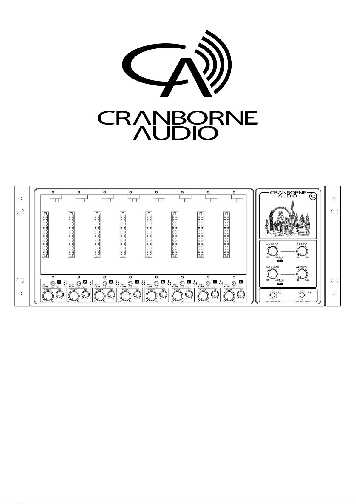
500ADAT - Analogue/Digital Hybrid ADAT
Expander, Summing Mixer, and 500 Series Rack
User Manual
500ADAT User Manual -Page 1- ©2019 Cranborne Audio Ltd

Welcome to our family
Cranborne Audio represents a commitment by four product designers to build an audio brand
that does things the right way. We don’t take shortcuts. We don’t compromise. We don’t
accept “good enough.”
We’re just like you. We’re musicians. We’re audio engineers.
We make products that we want to use. We create, innovate, and design with passion,
purpose, and belief. We strive to design products that remain accessible whilst offering the
highest quality and truly innovative new ways of working and achieving that sound that we all
desire.
Cranborne Audio, for us, means so much more than metal boxes with components in them.
These are our labours of love that embody and demonstrate our demand for excellence. By
distilling what matters and putting our soul into these tools, we hope to help other people
make magic and express themselves, and in some way, become part of our Cranborne Audio
family.
So welcome to our family. We care for our family. And we care about making your tracks,
albums, scores sound as good as they should.
500ADAT User Manual -Page 2- ©2019 Cranborne Audio Ltd

Cranborne Audio 500ADAT
Congratulations on your purchase of 500ADAT and thank you for selecting Cranborne Audio to
be a part of your music creation process.
What we set out to achieve with 500ADAT was putting control back into the hands of
musicians and engineers. In a sea of products that rely on computer integration and a “virtual
emulation” mentality, we set out to offer an alternative that places a true, customisable, and
flexible analogue front-end at the forefront of music creation - after all, the feel and touch of a
musician is analogue and that’s where the music begins.
Working in harmony with 500ADAT’s analogue stages is its high-performance digital stages.
Each and every component inside 500ADAT has been carefully considered to ensure that every
nuance of your 500 series module is translated into the best possible digital signal to be
processed. We employ converters with specifications that rival that of the best standalone
units whilst being governed by our master reference-grade clock featuring less than 0.5
picoseconds of jitter.
Cranborne Audio, for us, means so much more than metal boxes with components in them.
These are our labours of love that embody and demonstrate our demand for excellence. By
distilling what matters and putting our soul into these tools, we hope to help other people
make magic and express themselves, and in some way, become part of our Cranborne Audio
family.
So welcome to our family. We care for our family. And we care about making your tracks,
albums, scores sound as good as they should.
500ADAT User Manual -Page 3- ©2019 Cranborne Audio Ltd

500ADAT User Manual
Getting Started 6
Controls, Switches, and Connectors 6
Package Contents 8
Rack-Ear Orientations 9
Default Shipping Configuration 9
Note: 9
Recessed Configuration 10
Handle Configuration 10
Power Supply 11
Connecting Power 11
Disconnecting Power 11
Powering Procedures 12
Powering On 12
Powering Off 12
Installing and Removing 500 Series Modules 12
Installing Modules 12
Removing Modules 12
Hardware Setup 13
Feature Overview 14
500 Series Rack 14
Module Inputs 14
Inserts 14
Module Direct Outputs 15
Slot Bypass Switch 15
Source Switch 16
Chain Switch 17
500 Series Signal Flow 17
Summing Mixer 18
Mix Level & Pan 18
Mix Output 18
Summing Mixer Expansion Via C.A.S.T. LINK 19
Artist Monitoring Section 20
Aux/Monitor Blend 20
Aux Input Jacks 20
Aux Level 21
Aux Outputs 21
ADAT 22
Low-Jitter Internal Clock 22
Word Clock Input 22
Word Clock Output 23
Clock Settings DIP switches 23
Configuring Sample Rate 24
500ADAT User Manual -Page 4- ©2019 Cranborne Audio Ltd

C.A.S.T. 25
C.A.S.T. IN A,B,C & D (RRTT) 25
C.A.S.T. Requirements 26
Application Guides 27
Using 500ADAT without 500 series modules 27
Inserting 500 Series modules into DAW Sessions via ADAT 28
Using 500R8 and 500ADAT Together 29
C.A.S.T. LINK 30
Understanding C.A.S.T. 31
N22 31
N22H 31
Using N22 and N22H with 500ADAT 32
Technical Specifications 33
Digital Performance 33
Analogue Performance 34
System Performance 35
Power 35
Environmental 35
Dims/Weights 35
Troubleshooting 37
Important Safety Instructions 38
General Safety 38
Installation notes 38
Power Safety 39
CE Certification 39
FCC Certification 39
RoHS Notice 40
Instructions for disposal of WEEE by end users in the European Union 40
Electromagnetic Compatibility 40
500ADAT User Manual -Page 5- ©2019 Cranborne Audio Ltd

Getting Started
Controls, Switches, and Connectors
[1] Source Switch: Toggles the input source of
each 500 series slot between C.A.S.T., Analogue,
and ADAT sources.
[5] Power Switch: Safely powers on and off
500ADAT as well as any inserted 500 series
module. Tap to power on, press and hold to
power off.
[2] Mix Level & Pan Controls: Adjusts the level
and pan position of each 500 series slot into the
built-in Summing Mixer.
[6] Aux 1 & 2 Blend Controls: Blends the
Summing Mixer and Aux Input together into the
Aux 1 and 2 Busses independently.
[3] Chain Switch: Sends the output of the
preceding module into the input of the next. (1
into 2, 2 into 3, 3 into 4 etc).
[7+8] Aux 1 & 2 Level Controls: Adjusts the main
level of Aux 1 and 2 to their discrete headphones
and Aux Output 1/4” jack outputs on the rear
panel.
[4] Slot Bypass Switch: Bypasses the 500 series
slot to enable recording without a module
installed. All other features function normally
when slot bypass is engaged.
[9] Aux 1 & 2 Headphones Outputs: Used for
connecting Independent headphones to Auxes 1
and 2.
500ADAT User Manual -Page 6- ©2019 Cranborne Audio Ltd

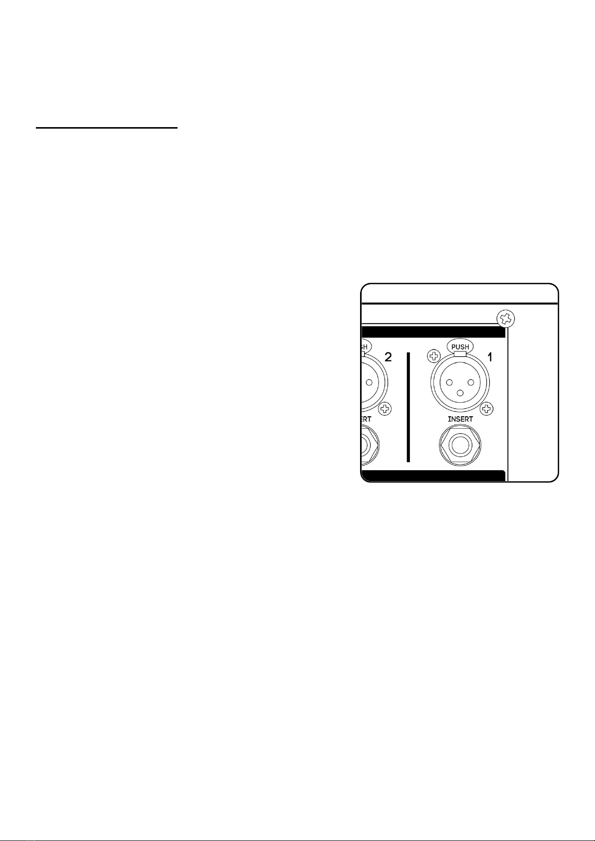
[1] Module Input: Connects balanced XLR analogue
inputs into each 500 series slot. Input sensitivity varies
depending on the type of module inserted.
[8] USB 2.0: Used for software updating and
non-audio purposes only. Cannot be used as an
audio interface.
[2] Insert: Connects external equipment in-line after
the 500 series module but before the A/D of each 500
series slot. Utilises a standard Y-split or insert cable.
(Tip=send, Ring=return).
[9] Grounding Post: Enables direct binding to
chassis ground to help eliminate ground loops in
specific setups.
[3] Module Direct Outputs: Sends balanced, line-level
outputs of each 500 series slot for connection to
external converters and equipment. Module Direct
Outputs are positioned post-insert point, pre Mix
Level.
[10] Aux Input: Connects analogue playback
sources from external audio interfaces directly
into 500ADAT’s monitoring paths.
[4] C.A.S.T. A, B, C, & D Inputs: Enables I/O relocation
and expansion via Cranborne Audio C.A.S.T. enabled
breakout boxes.
[11] Power: Provides 500ADAT with power via the
provided external 24v 5A DC power supply. No
other power supply should be used.
[5] ADAT I/O: Interfaces 500ADAT’s 8-in/8-out ADAT
optical lightpipe channels directly into your audio
interface of choice.
[12] C.A.S.T. Link: Enables linking of the Summing
Mixers between 500ADAT and a 500R8. C.A.S.T.
link transmits the Summing Mixer into the
connected 500R8 for monitoring.
[6] Word Clock I/O: Enables sending and/or receiving
word clock information to/from external digital
devices.
[13+14] Aux 1 & 2 Outputs: Connects balanced line
outputs of 500ADAT’s Aux 1 and 2 Busses to
external monitoring devices or similar via 1/4”
jacks.
[10] Clock Settings: Adjusts 500ADAT’s Clock Settings
including Clock Source and Sample Rate.
[15] Mix Output: Connects line outputs of
500ADAT’s built-in Summing Mixer directly to
external converters or similar via 1/4” jacks.
500ADAT User Manual -Page 7- ©2019 Cranborne Audio Ltd

Package Contents
So now your 500ADAT is out of it’s packaging, you’re probably itching to get it powered on and
making music! But before you get started, please read the sections below that will help guide
you through the process of getting 500ADAT setup, plugged in, and ready-to-record as quickly
as possible!
The following items can be found in the packaging alongside 500ADAT:
- External power adapter
- IEC cable
- 16 module fixing screws (crosshead, 4-40 thread size)
- Allen key (2.5mm)
- Quickstart Guide
500ADAT User Manual -Page 8- ©2019 Cranborne Audio Ltd

Rack-Ear Orientations
There’s more to 500ADAT’s rack ears than meets the eye. The default shipping configuration
features the rack ears mounted flush to the front panel of 500ADAT - the most common
method for rack-mounting.
500ADAT can also be set backwards into its rack ears to allow the front panel controls to sit
behind the front of the rack for protection during travelling and location recording.
Finally, both of 500ADAT’s rack ears can be removed, placed back-to-back, and attached to
500R8 as a convenient carry-handle for travelling.
Depending on your desired use case, you may need to reorientate the rack ears and position
the rubber feet to best suit your application by using the supplied 2.5mm allen key.
Default Shipping Configuration
Standard rack-ear configuration used for rack-mounting 500ADAT into standard 19” rack. If you
would like to secure 500ADAT into a 19” rack, the rubber feet should be removed from the unit
using the allen key provided.
Note:
Whilst 500ADAT features plenty of ventilation to ensure that it remains cool during
operation, some 500 series modules (and valve-based modules in particular) can
run extremely hot and will cause 500ADAT to heat up quickly. When rack mounting
500R8, please leave a 1u space above and below the unit to ensure that the
ventilation is clear and fully-effective.
500ADAT User Manual -Page 9- ©2019 Cranborne Audio Ltd
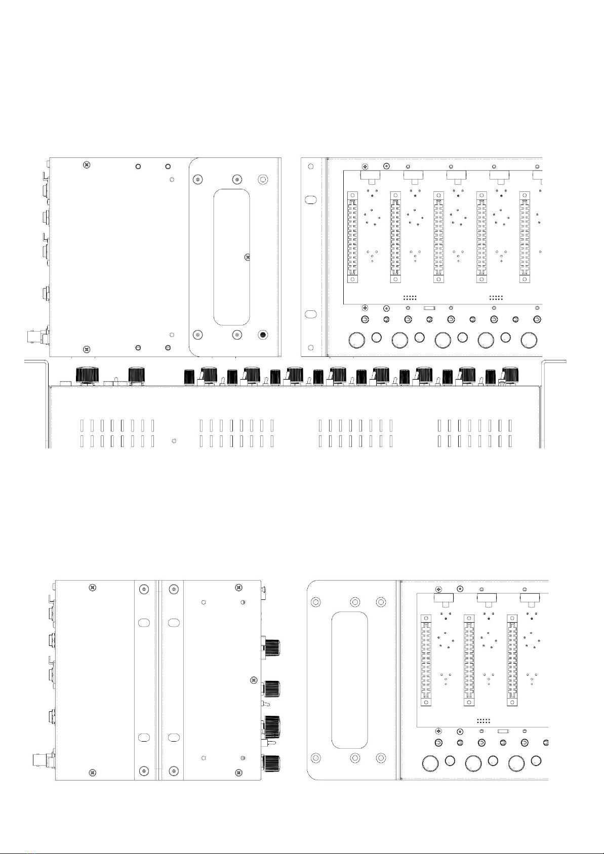
Recessed Configuration
Recesses 500ADAT into a 19” rack to protect all of its front panel controls during transportation.
To position the rack ears in this configuration, remove both rack-ears and slide them forward
until the holes align with a second set of thread posts on 500ADAT. Once aligned, secure the
rack-ears with the 8x rack ear screws using the allen key provided.
Handle Configuration
Creates a convenient carry-handle for short-distance transportation. To position the rack ears
in this configuration, remove both of the rack ears and reposition them back-to-back onto the
left side of 500ADAT. Secure them into place using 4x rack ear screws and the allen key
provided. Store the leftover rack-ear screws in a safe place for future use.
500ADAT User Manual -Page 10- ©2019 Cranborne Audio Ltd

Power Supply
500ADAT is powered via an external 24v 5A DC
switch-mode power supply that supports any operating
voltage from 100 to 240v.
Switch mode power supplies can exhibit switching noise
but 500ADAT features linear regulation on the DC inlet
to ensure that power noise and intermodulation
distortion doesn't find itself on the audio rails.
Each 500 series slot features 250mA of power as well as
extra headroom if a module is drawing even more
current for a maximum of 2A across all 8 slots.
500ADAT’s Power delivery is also made via a latching
4-pin connector that is designed to provide a secure
connection to the chassis with protection against
accidental removal.
Connecting Power
Align the metal pins and plastic locator of the plug with the power inlet. Once located, push
the connector firmly into the socket whilst holding the plug’s outer housing and not the cable
itself.
Disconnecting Power
Grip the body of the plug firmly and pull the body of the connector back from the socket. The
plug’s outer casing will pull back and release the safety latch to allow the plug to be pulled out
of the socket.
Note:
Excessive strain or a sudden tug/shock to the power cable could cause damage to
the cable strain relief as well as the hardware contact points associated with the
power input and power supply.
500ADAT User Manual -Page 11- ©2019 Cranborne Audio Ltd
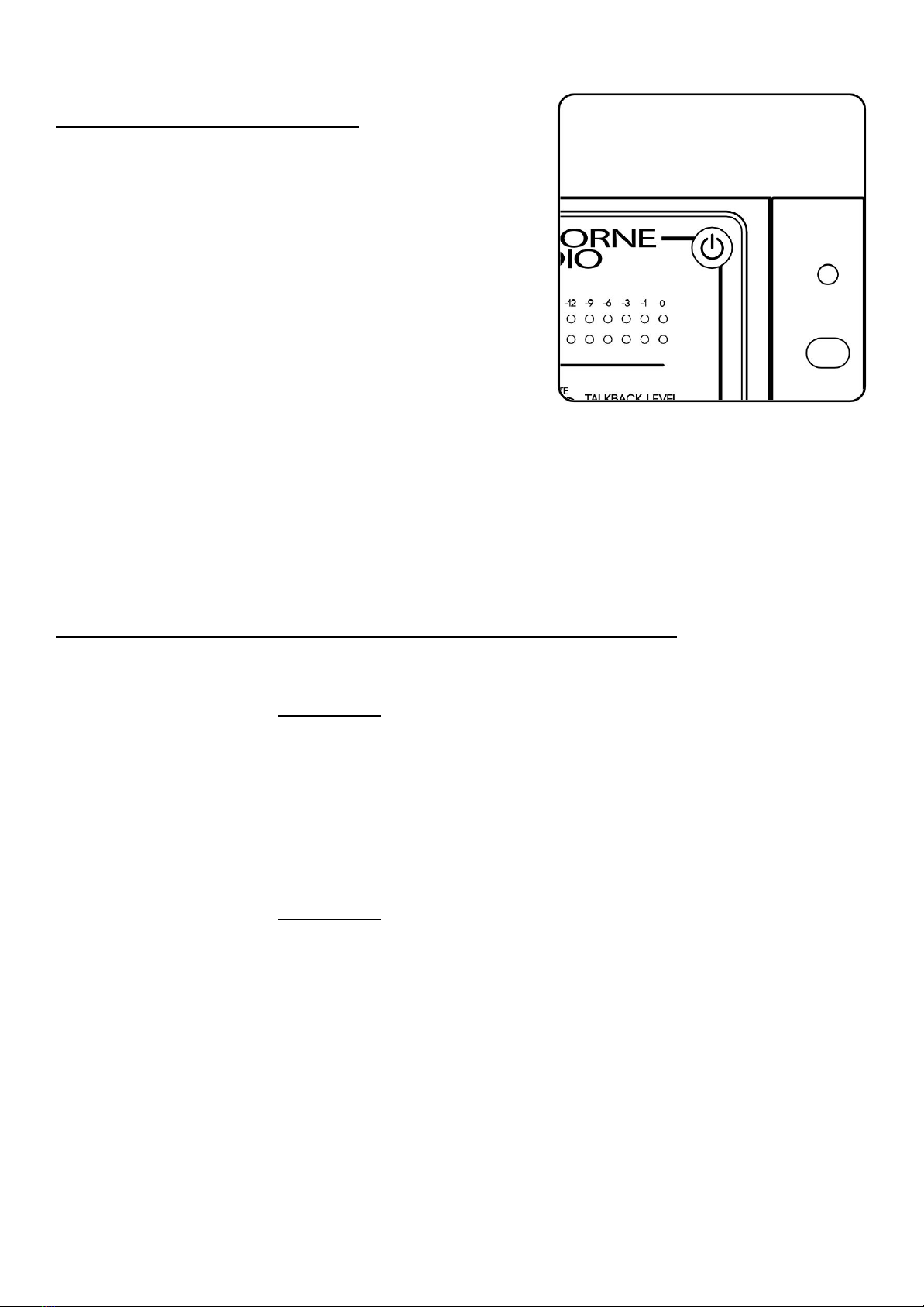
Powering Procedures
Powering On
First, make sure your speakers are switched off and any
headphones are disconnected. Briefly tap the power
button located on the top right of 500ADAT’s front
panel. The power icon will illuminate blue and you will
hear soft ‘clicking’ as 500ADAT’s internal relays actuate.
You may now switch on your external equipment
sequentially, leaving your speakers until last.
Powering Off
First, make sure your speakers are switched off and any
headphones are disconnected. Press and hold the
power button for approximately 3 seconds. The power icon will deluminate and you will hear
the soft ‘clicking’ of the relays indicating that the unit has been powered off.
Note:
Please follow these safe powering sequences carefully in order to prevent any
unwanted pops and spikes causing damage to downstream audio components
including speakers and headphones.
Installing and Removing 500 Series Modules
Installing Modules
1. Ensure 500ADAT is powered off and the power connector has been removed. Wait 30
seconds before continuing.
2. Firmly touch the metal chassis of 500ADAT to discharge any built-up static electricity.
3. Carefully pick up your 500 series module and locate its conductive edge into the
backplane connector of 500ADAT.
4. Once located, push the module into place and secure the module into the rack using
the supplied 4-40 screws - be careful not to over tighten and strip the screw or thread.
Removing Modules
1. Ensure 500ADAT is powered off and the power connector has been removed. Wait 30
seconds before continuing.
2. Firmly touch the metal chassis of 500ADAT to discharge any built-up static electricity.
3. Remove the 4-40 module fixing screws and store them in a safe place for future use.
4. Firmly pull the 500 series module to release the module from the backplane connector
of 500ADAT and then carefully remove the module from the rack itself.
Note:
Removing or installing modules when any 500 series rack is powered on can
cause irreparable damage to the backplane connector, supporting circuitry,
and the 500 series module. Damage caused when “Hot Swapping” or
installing/removing modules whilst 500ADAT is powered on is not covered
under Cranborne Audio’s Warranty.
500ADAT User Manual -Page 12- ©2019 Cranborne Audio Ltd
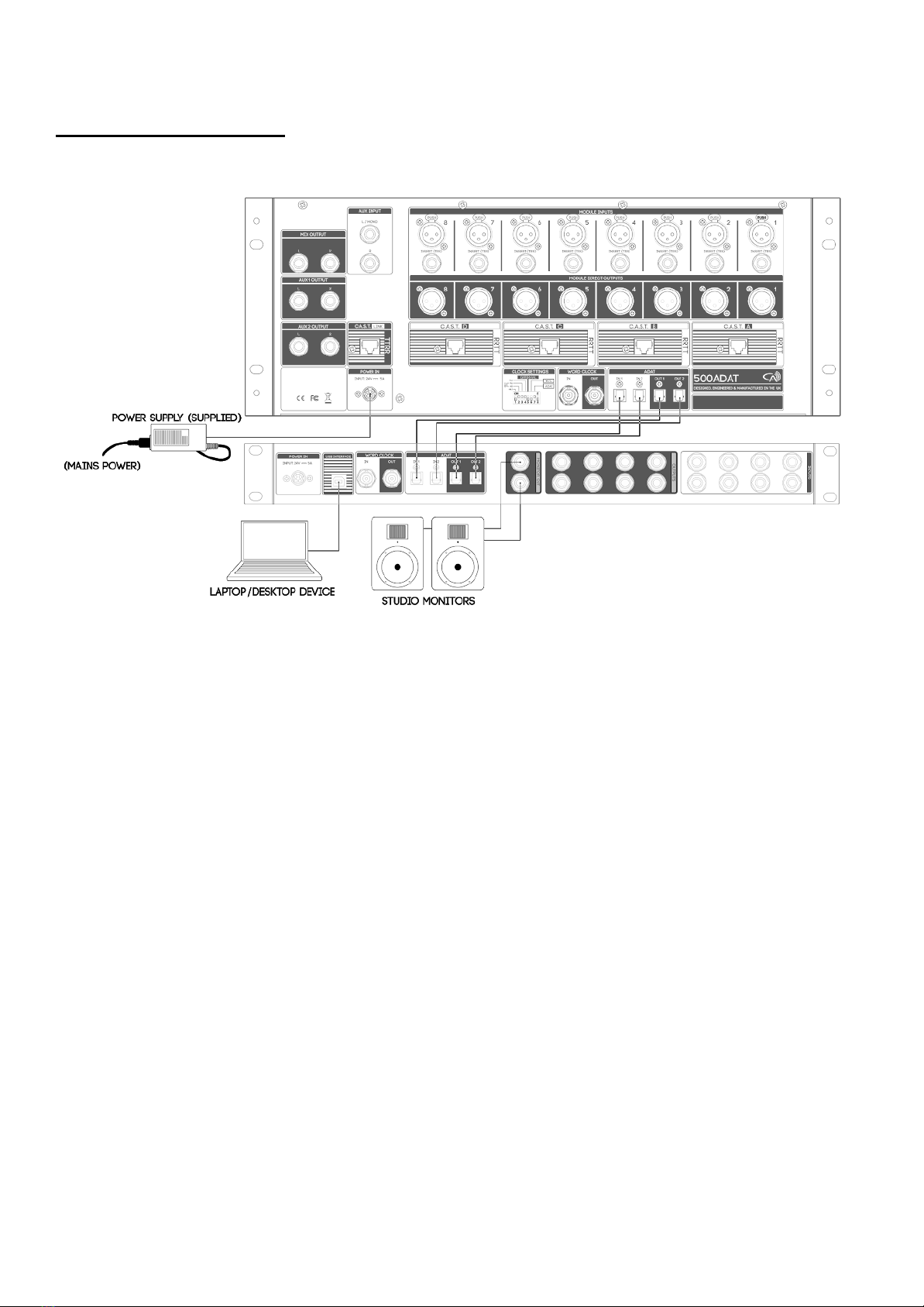
Hardware Setup
This hardware setup diagram will get 500ADAT connected to your audio interface and ready
for recording.
1) Connect mains power into the external PSU supplied in 500ADAT’s packaging and
connect the power connector into 500ADAT’s power inlet.
2) Connect 500ADAT to your audio interface using Optical Cables with Toslink connectors:
a) 500ADAT’s ADAT outputs should be connected to your audio interface’s ADAT
Inputs.
b) 500ADAT’s ADAT inputs should be connected to your audio interface’s ADAT
outputs.
2) Configure 500ADAT’s rear panel Clock Settings DIP switches:
a) Select your desired Sample Rate using DIP switches 1-4.
b) Configure DIP switch 5 into its UP/ON position.
c) All other DIP switches should be DOWN/OFF.
3) Power On 500ADAT using a brief tap of the Power button.
4) Configure your audio interface to clock from via ADAT and ensure your project’s Sample
Rate matches the Sample Rate set on 500ADAT’s Clock Settings DIP switch.
a) Consult the manufacturer of your audio interface for instructions on how to clock
externally via ADAT.
Note:
To achieve 500ADAT’s best performance, 500ADAT should be set as the clock
master of your system and the project sample rate should match 500ADAT’s.
500ADAT User Manual -Page 13- ©2019 Cranborne Audio Ltd
Feature Overview
500 Series Rack
The centrepiece of 500ADAT is it’s 8-slot, high-current 500 series rack. Each slot features an
abundance of I/O located on the rear panel that allows analogue input, insert, and output
connectivity per-slot much like a standard standalone 500 series rack.
Each 500 series slot is tightly integrated with 500ADAT’s converters and ADAT interface for
recording each inserted 500 series module as well as playing back ADAT sources through each
500 series module. Each 500 series slot features front-panel switches that determine its input
source and enable deeper integration with 500ADAT’s Summing Mixer and ADAT Audio
Interface.
Module Inputs
Each 500 series slot features a dedicated balanced XLR
input that is used to connect analogue signals into each
500 series module. The module input XLR can accept
mic, line, or hi-z sources depending on what module is
inserted and it’s input sensitivity options.
Note:
In instances where the 500 series module
features it’s own XLR/Jack input on the front
panel, it is advised to check with the
manufacturer of the module to determine
which input should be used for your desired
application.
Inserts
Each 500 series slot features a dedicated Insert connection that utilises a TRS jack socket in a
similar configuration that is commonly found on mixing consoles. This Insert point allows
external audio equipment such as 19” rackmount compressors and EQs to be inserted into the
audio path and recorded. The Insert is situated after the 500 series slot but before the ADC and
ADAT output path in the signal which means that the effect Inserted will be heard on the
ADAT output, Module Direct Outputs, and internal Summing Mixer.
Insert Wiring
Tip= Send, Ring= Return, Sleeve= Ground
To connect external audio equipment into 500ADAT via its Insert, you will need to use a
standard Y-split or insert cable that splits a TRS jack into 2 separate connections - a send and
return - to two mono ¼ jacks or male/female XLRs.
The ‘Send’ connector (Tip + Sleeve) should be connected to the input of your outboard
equipment and the ‘Return’ connector (Ring + Sleeve) should be connected to the output of
your outboard equipment.
500ADAT User Manual -Page 14- ©2019 Cranborne Audio Ltd

Note:
500ADAT does not feature a dedicated switch to engage the insert point and so to
fully bypass the insert point during recording/mixing you will need to bypass
Inserted effect itself or disconnect the insert point.
Module Direct Outputs
Each 500 series slot features its own Module Direct
Output that is a fully balanced XLR line-level output of
each 500 series module that can be used to connect to
external A/D converters or advanced monitoring
systems. The Module Direct Outputs are positioned PRE
the Mix Level controls for each 500 series slot and mirror
what is sent into the ADAT interface.
You can also use the Module Direct Outputs to send
audio from one slot to another by simply using an XLR
cable.
Note:
For advanced patching combinations, you can
connect the module inputs and outputs of
500ADAT to a patchbay to allow convenient
re-ordering of modules as well as advanced
channel strip creation without accessing the
rear panel.
Slot Bypass Switch
The Slot Bypass switch is located on the backplane
connector by each 500 series slot and can be used to
bypass the slot if no 500 series modules are inserted.
Bypassing the slot allows you to connect line-level
sources such as external mic preamps and effects units
directly into the rear panel inputs of 500ADAT and
record those signals directly into the DAW via it’s ADAT
connections.
The Slot Bypass switch is available per-slot which allows
you to occupy some of 500ADAT’s 500 series slots with
modules whilst using the others to record line-level
sources.
The Module Source, Insert, Module Direct Output, and
Summing Mixer features function as normal for each slot that has the Slot Bypass switch
active.
500ADAT User Manual -Page 15- ©2019 Cranborne Audio Ltd

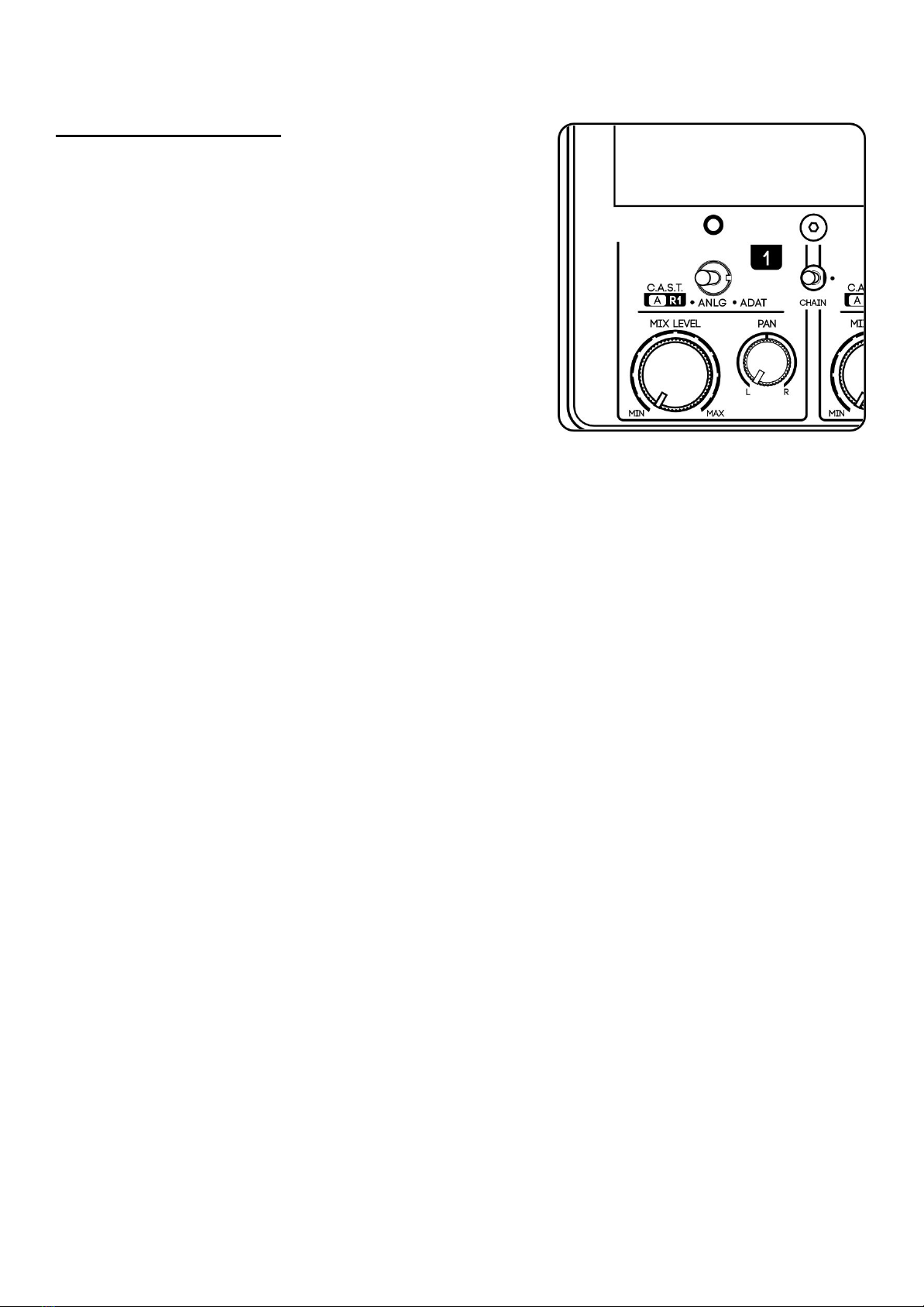
Source Switch
Each 500 series slot on 500ADAT features a Source
Select switch on the front panel that is used to
determine which audio signal is sent into the input of
the inserted 500 series module.
These source options include:
C.A.S.T.
This configures the 500 series slot to receive
signal via the corresponding C.A.S.T. inputs. There
are 4 C.A.S.T. Inputs on the rear panel and they
correspond to pairs of 500 series slots. This port is
intended for expansion via C.A.S.T. enabled
breakout boxes.
For a detailed explanation of C.A.S.T., please read
the “C.A.S.T. IN A, B, C, & D (RRTT)” section of this
manual.
ANLG
This configures the 500 series slot to receive signal
via the corresponding rear Module Input XLR
connection.
ADAT
This configures the 500 series module to receive signal via the corresponding ADAT
channel from 500ADAT’s built-in ADAT Interface.
Note:
Switching between source selections whilst monitoring the 500 series slots can
cause audible “clicks and pops” through your audio system depending on what
module is inserted and its input/output gain. Please take care and reduce the
listening volume prior to switching the Source Selector switch.
500ADAT User Manual -Page 16- ©2019 Cranborne Audio Ltd
Chain Switch
The Chain Switch overrides the Source Select switch and sends the audio signal from one 500
series slot into the next 500 series slot. This can be used to create chains of modules for
advanced tonal shaping and channel strip creation during tracking and mixing.
Slots can be chained from left to right and can be created independently from one another for
a total of 4 chains of 2, 2 chains of 4, 1 chain of 8, or any configuration in between.
Note:
When chaining channels, all existing Module Direct Outputs and ADAT outputs
work as normal for all contributions in the chain. For example, if you have a mic
preamp in slot 1, an EQ in slot 2, and a compressor in slot 3, you can record the
ADAT output of slot 3 to record the summed result of all 3 modules, record the
ADAT output of slot 2 to record just the preamp and EQ, or record the ADAT output
of slot 1 to print the dry effect. You can also record all 3 parts of the chain
simultaneously for more flexibility later on in the mix stage.
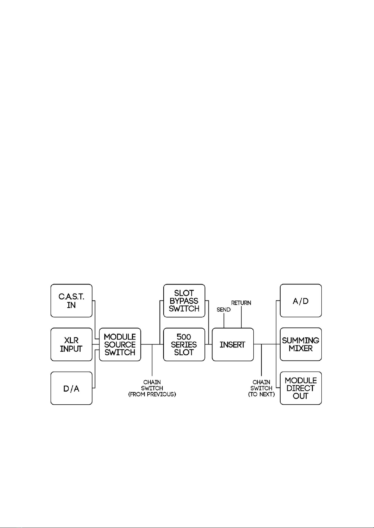
500 Series Signal Flow
Each 500 series slot is connected to multiple sources and destinations that facilitate all of the
complex internal recording and mixing aspects of 500ADAT. To better understand where each
slot is positioned in the signal path in relation to its converters, the below diagram displays a
rough overview of the signal flow of one 500 series slot to its possible destinations.
Note:
The output of each module is sent to 3 destinations at all times irrespective of the
Module Source or Chain switches.
500ADAT User Manual -Page 17- ©2019 Cranborne Audio Ltd
Summing Mixer
500ADAT features a high-headroom 8-to-2 analogue
Summing Mixer that can be used to sum eight analogue
audio paths from the 500 series slots into a single stereo
track for recording back into your DAW.
You can use the eight 500 series slots as well as their
insert points to apply analogue colouration and
processing onto your audio tracks/stems before they are
summed using the Summing Mixer. The input sources
Summing Mixer are determined by the source switches
below each 500 series slot to allow for summing
Analogue, C.A.S.T., or ADAT sources.
The Summing Mixer has a headroom of +24dBu to allow
you to drive transformer/valve-based equipment to get
the most range of colouration available without fear of overdriving the Summing Mixer.
Mix Level & Pan
The Mix Level and Pan controls are used to balance the volume and pan position of each 500
series slot within the Summing Mixer.
Mix Level
Adjusts the level of the 500 series slot into the Summing Mixer. Mix Level is a variable
control with a range of -∞ to +10dB
Pan
Adjusts the pan position of the 500 series slot into the Summing Mixer. Pan is a variable
control with a centre detent that operates a -4.5dB pan law.
Mix Output
The Summing Mixer and its stereo output is sent directly to two dedicated ¼” jack outputs on
the rear panel of 500ADAT labelled ‘Mix Output’. These connections can be used to send the
summed stereo mix onwards to the line inputs of the connected audio interface or monitoring
systems.
The Summing Mixer does not feature its own master volume control. This in order keep the
analogue path as pure as possible and ratain the maximum headroom and lowest THD. Use
the individual Mix Level and Pan controls for each 500 series slot to reduce the overall level of
the Summing Mixer and prevent clipping its A /D converter or internal signal paths.
500ADAT User Manual -Page 18- ©2019 Cranborne Audio Ltd

Summing Mixer Expansion Via C.A.S.T. LINK
The C.A.S.T. LINK port on the rear panel of 500ADAT can
be connected to the corresponding C.A.S.T. LINK port on
500R8 to double the channel count of available
analogue summing from 8 to 16 channels.
The C.A.S.T. LINK connection Transmits 500ADAT’s stereo
summing mixer (TT) whilst simultaneously receiving the
stereo Aux Mix (RR) from the connected 500R8 via the
same shielded Cat5 cable. Those four audio paths are
broken down as follows:
Receive 1 + 2
Receives 500R8’s Stereo Aux Mix
The two receive paths of the C.A.S.T. LINK connector are sent to 500ADAT’s Aux Blend
controls to enable the user to blend-in 500R8’s Aux mix with 500ADAT’s summing mixer
for monitoring via 500ADAT’s 2 headphones outputs.
The Receive path from the connected 500R8 also features the talkback that has been
generated on 500R8 so that the engineer operating the session can communicate with
musicians connected to the headphones outputs of 500ADAT.
Transmit 1 + 2
Transmits 500ADAT’s Summing Mixer (Pre Aux Blend controls)
The two transmit paths of the C.A.S.T. LINK connector featuring 500ADAT’s Summing
Mixer output are combined with 500R8’s own Summing Mixer and sent directly to USB
Inputs 9/10 and physical Mix Outputs of 500R8. In this configuration, 500ADAT doubles
the system’s available Summing Mixer channels to 16.
500ADAT User Manual -Page 19- ©2019 Cranborne Audio Ltd
Artist Monitoring Section
There are two identical monitoring paths on 500ADAT;
Aux 1 and Aux 2. Each path has its own Blend controls
that are used to adjust the balance between the
analogue Summing Mixer and incoming Aux
Input/C.A.S.T. Link connector.
500ADAT features dedicated reference-quality Aux
and Monitor headphones outputs on the front panel
as well as various line output options on the rear panel
to distribute monitoring wherever it is needed.
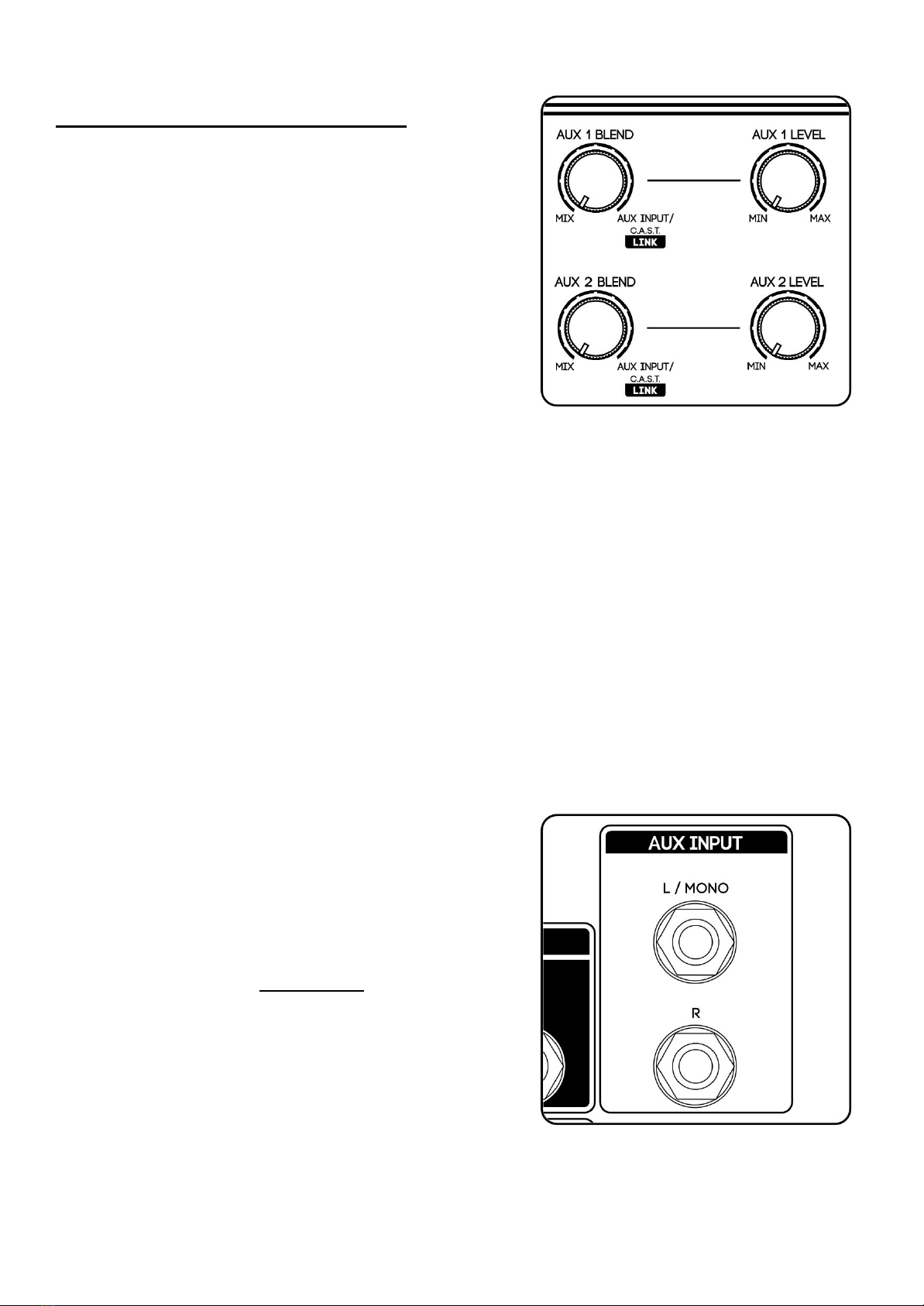
Aux/Monitor Blend
The Blend controls are the main contributing factor for creating great sounding artist monitor
mixes. These blend controls adjust the balance of the mix between two different elements:
Mix
Comprises of the analogue Summing Mixer and is created using the Mix Level and Pan
controls located below each 500 series slot. The Mix is typically comprised of live sources
but can also feature channels being sent into the modules via ADAT.
DAW
Comprises of a stereo playback source that is incoming from the DAW and sent into
500ADAT via it’s Aux Input 1/4” Jack returns. The Aux Input is typically comprised of pre
recorded elements, click tracks, and VSTs from within the connected audio interface but
can also feature live instruments by utilising software monitoring within the DAW.
The Blend controls can be set anti-clockwise to listen to the Summing Mixer directly, clockwise
to listen to the Aux input directly or anywhere in-between to create a custom balance of the
two sources.
Aux Input Jacks
The Aux Input jacks on the rear panel of 500ADAT can
be used to send stereo playback from the connected
audio interface into 500ADAT’s Aux 1 & 2 mixers and
headphones outputs.
The Aux Input jacks are unbalanced connections to
facilitate the L/Mono normalling circuit and enable the
analogue Aux Input Input to operate in mono if just
the left jack is inserted.
Note:
Please consult the user manual of your
external playback device to find out
the best procedure for connecting its balanced outputs into the Aux Input
unbalanced ¼” jack inputs.
500ADAT User Manual -Page 20- ©2019 Cranborne Audio Ltd
Other manuals for 500ADAT
1
Table of contents
Other Cranborne Audio Music Mixer manuals


