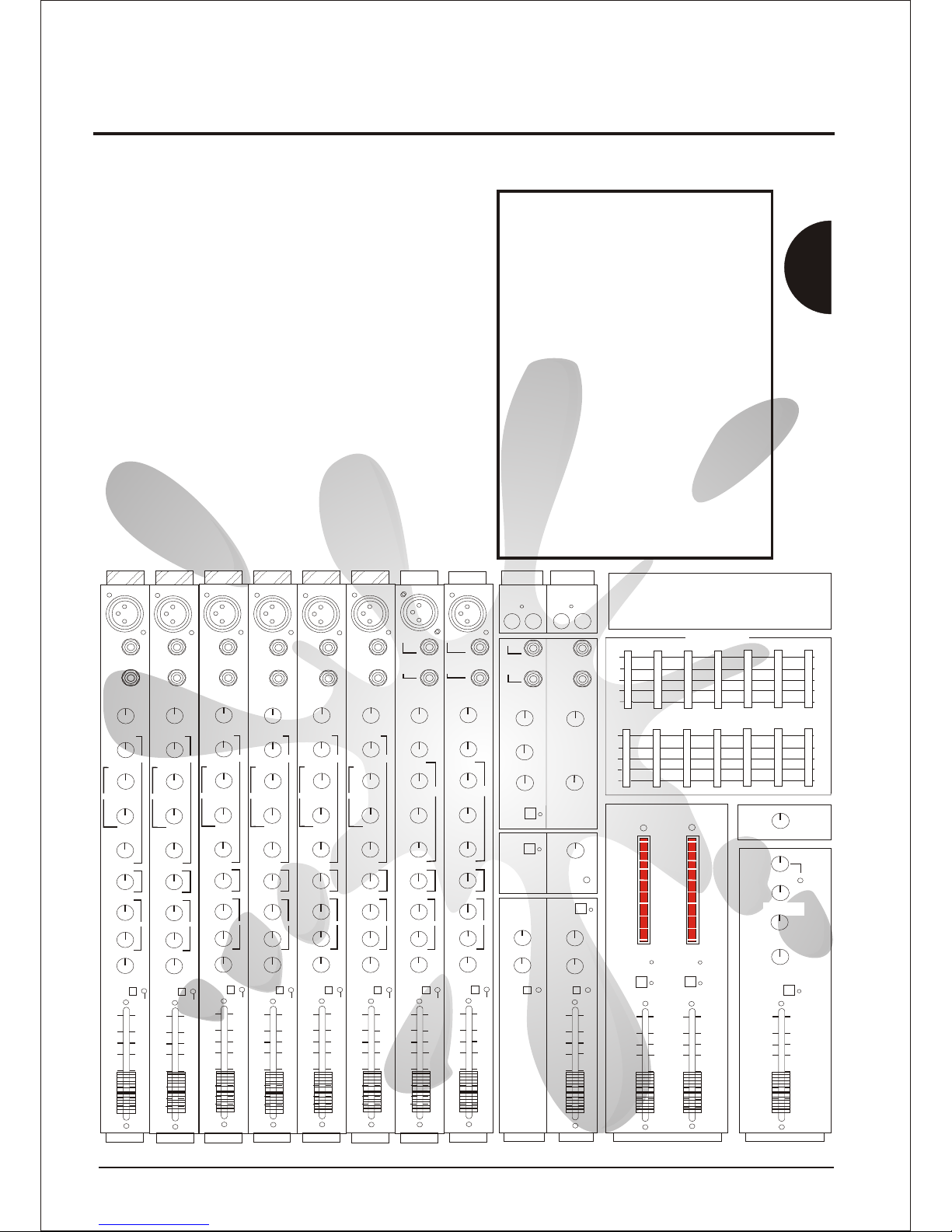
Concept
Concept Manual
9
o
oo
o
O O O O O FX PROCESSOR
o
o
o
o
o o
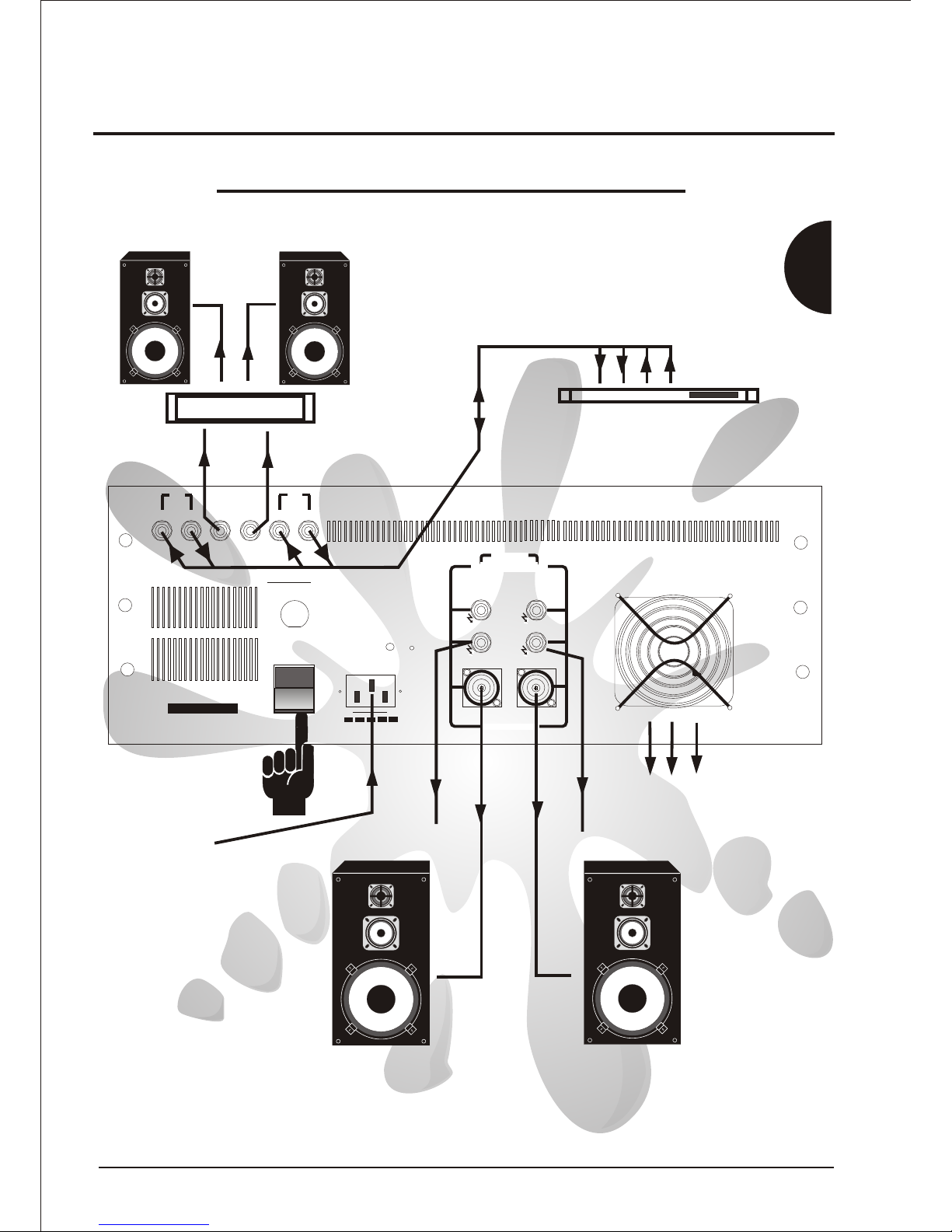
POWER AMPLIFIER
STEREO
RIGHT
DO NOT OBSTRUCT FAN APERTUREDO NOT OBSTRUCT FAN APERTURE
DO NOT OBSTRUCT INLET VENTSDO NOT OBSTRUCT INLET VENTS
MINIMUM LOAD = 4 OHMSMINIMUM LOAD = 4 OHMS
PIN -1GROUNDPIN -1GROUND
PIN +1 SIGNALPIN +1 SIGNAL
SPEAKER OUTPUTSSPEAKER OUTPUTS
RIGHTRIGHT
CHANNELCHANNEL
LEFTLEFT
CHANNELCHANNEL
SPEAKER OUTPUTSSPEAKER OUTPUTS
SPEAKER OUTPUTSSPEAKER OUTPUTS
OUTPUT POWEROUTPUT POWER
300 WATTS300 WATTS
OUTPUT POWEROUTPUT POWER
300 WATTS300 WATTS
PIN -1GROUNDPIN -1GROUND
PIN +1 SIGNALPIN +1 SIGNAL
MINIMUM LOAD = 4 OHMSMINIMUM LOAD = 4 OHMS
MADE IN THE UNITED KINGDOM BY
BLT Industries Ltd
MADE IN THE UNITED KINGDOM BY
BLT Industries Ltd
SERIAL NoSERIAL No
RETURNRETURN SENDSEND
MASTER
RIGHT
MASTER
RIGHT
/LEFT + RIGHT/LEFT + RIGHT
INSERTINSERT
MASTER
MASTER
RIGHTRIGHT
LINELINE
OUTOUT RETURNRETURN SENDSEND
MASTER
LEFT
MASTER
LEFT
INSERTINSERT
MASTER
MASTER
LINELINE
OUTOUT
LEFTLEFT
MONITORMONITOR
CAUTION
TO AVOID FIRE HAZARD
REPLACE ONLY WITH SAME TYPE AND RATING
CAUTION
TO AVOID FIRE HAZARD
REPLACE ONLY WITH SAME TYPE AND RATING
CAUTION
DISCONNECT POWER CORD
BEFORE REMOVING TOP COVER
CAUTION
DISCONNECT POWER CORD
BEFORE REMOVING TOP COVER
POWER FUSE RATINGPOWER FUSE RATING
220V/230V/240V T5A220V/230V/240V T5A
100/120V100/120V T10AT10A
CAUTION
REFER TO USER MANUAL
BEFORE USING THIS MANUAL
CAUTION
REFER TO USER MANUAL
BEFORE USING THIS MANUAL
CAUTIONCAUTION
WARNING
TO REDUCE THE RISK OF FIRE OR
ELECTRIC SHOCK DO NOT EXPOSE
THIS APPLIANCE TO RAIN OR
MOISTURE
WARNING
TO REDUCE THE RISK OF FIRE OR
ELECTRIC SHOCK DO NOT EXPOSE
THIS APPLIANCE TO RAIN OR
MOISTURE
WARNING
THIS APPARATUS MUST BE EARTHED
WARNING
THIS APPARATUS MUST BE EARTHED
MAXIMUM POWER CONSUMPTIONMAXIMUM POWER CONSUMPTION
SUPPLY VOLTAGESUPPLY VOLTAGE
~240V~240V ~230V~230V ~220V~220V ~120V~120V ~110V~110V
DO NOT OBSTRUCT INLET VENTSDO NOT OBSTRUCT INLET VENTS
DO NOT OBSTRUCT FAN APERTUREDO NOT OBSTRUCT FAN APERTURE
AIR OUTLETAIR OUTLET
1000 WATTS 50/60 Hz~1000 WATTS 50/60 Hz~
Switch On hereSwitch On here
Connect Mains Power HereConnect Mains Power Here
To more speakersTo more speakers
To more speakersTo more speakers
* Hot Air Outlet *
Do Not Obstruct
* Hot Air Outlet *
Do Not Obstruct
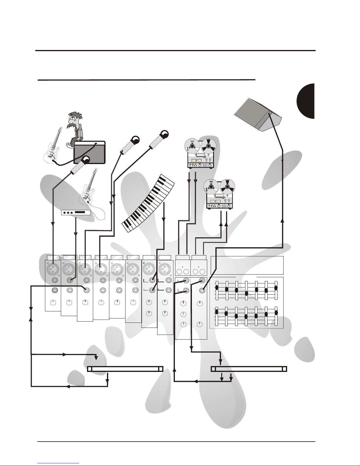
Connect Effects or Loudspeaker controller here
Connect Effects or Loudspeaker controller here
Slave out to more Amps + Speakers here
Slave out to more Amps + Speakers here
Mixer `Sends' to FX/controller `Inputs'
Mixer `Returns to FX/controller `Outputs'
Mixer `Sends' to FX/controller `Inputs'
Mixer `Returns to FX/controller `Outputs'
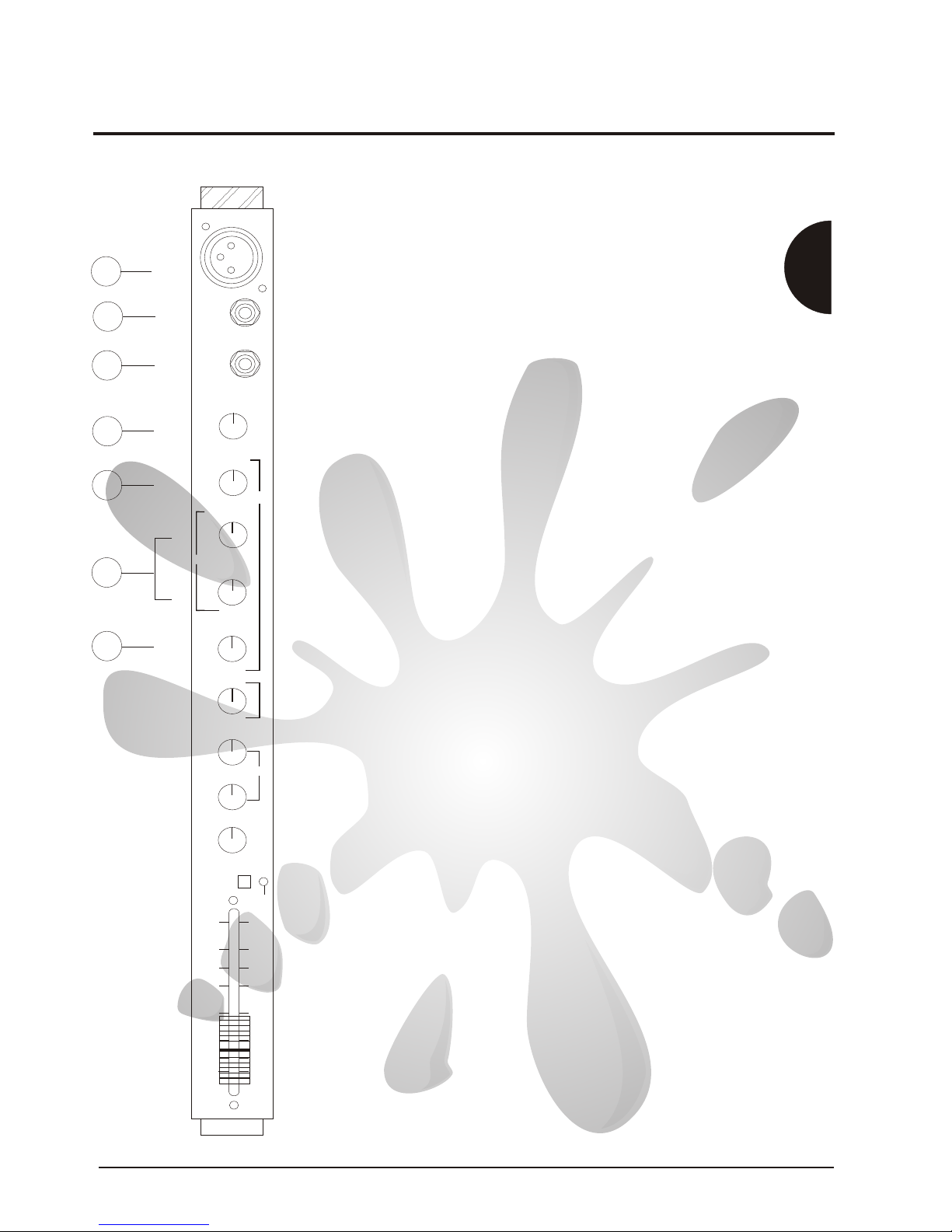
Concept 10/16 Quick Set Up Guide