Trident 88 Owners Manual10
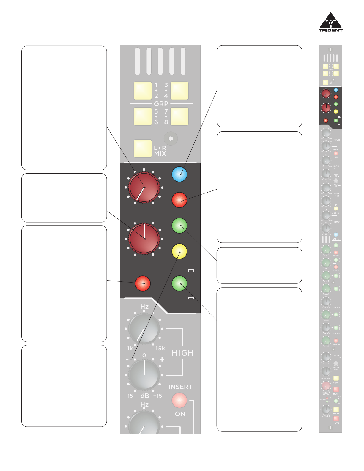
Trident 88 The Group Section
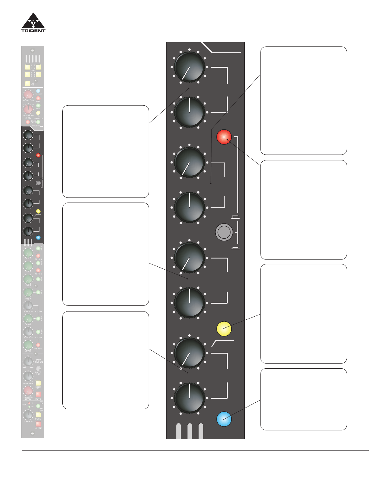
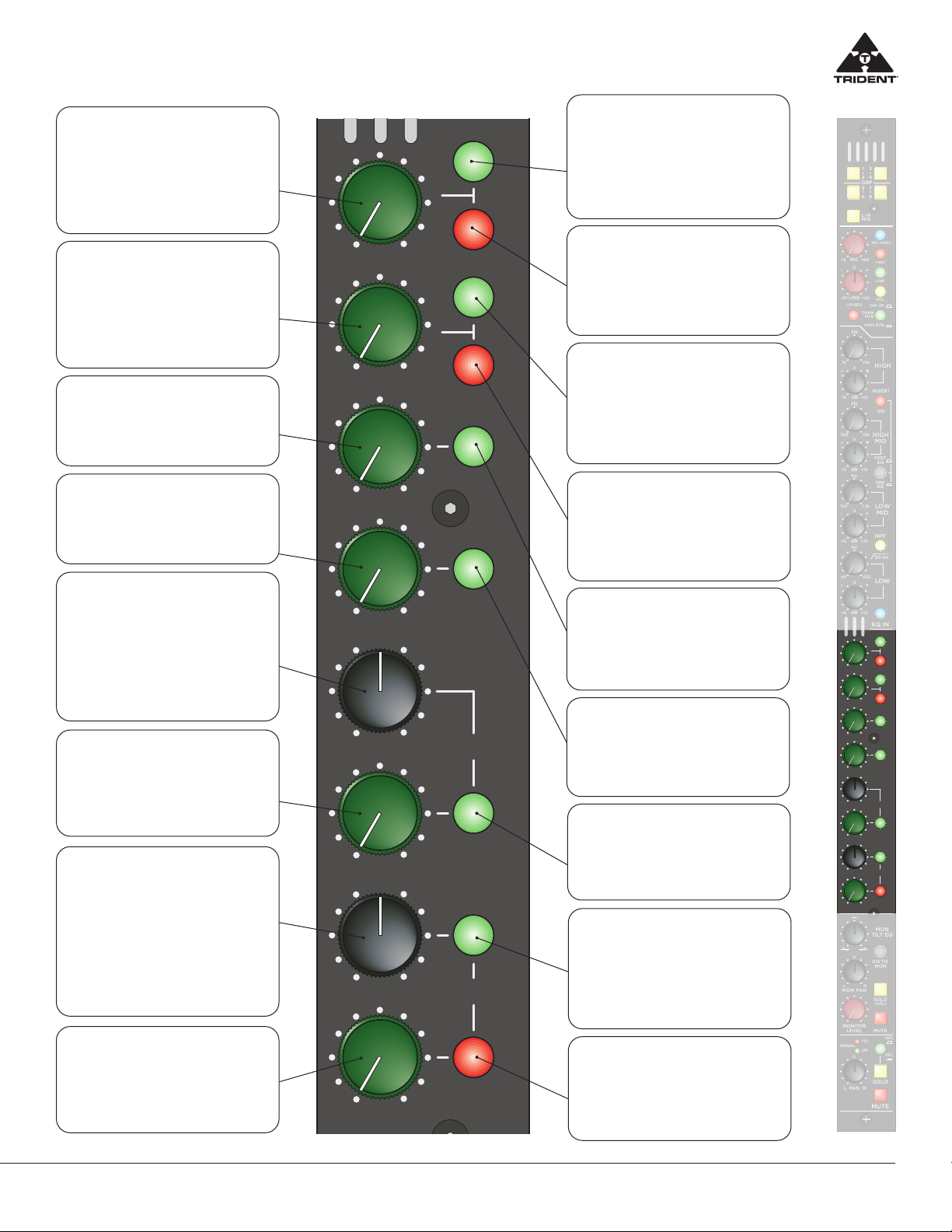
Trident 88 Input Channel Monitor Section
MON PAN
(Monitor Pan) Control
This control blends the post moni-
tor level signal between the Left and
Right buses. When at the centre de-
tented position, both Left and Right
buses are fed equal amounts of signal
(each down by 3dB).
MONITOR LEVEL Control
Adjusts the monitor signal level to
the Left/Right bus.
SOLO (AFL)
When pressed, routes the monitor
(post level and pan) signal to the solo
bus. Additionally this switches the Main
Monitor Output (normally feeding the
Left/Right mix) to source the signal
from the AFL/PFL Master Level in the
Master section as well as to trigger LED
indicators in the Master section and
meter-bridge stating a solo has been
pressed.
MONITOR MUTE
When pressed will mute the monitor
signal to the Left/Right bus. It is rec-
ommended when the monitor section
is not being used that it be muted.
AFL/PFL Select
Selects the channel source feed that
will be fed to solo bus when the chan-
nel SOLO is pressed. UP - solo system
is fed from the channel post fader/post
pan pot point and is a stereo signal
that follows the pan pot. This allows
the user to monitor the channel in the
solo system and to see its contribution
to the mix. DOWN - solo system is fed
from the channel pre fader point and is
a mono source. This allows the user to
monitor the signal in the solo system
before the channel fader/mute, allow-
ing the user to check the signal in the
channel without being routed to any
output buses.
EQ to MON
Assigns the 4 band channel EQ to the
Monitor Section, the TILT EQ is then
inserted to the Channel path. Note:
this switch is not illuminated.
MON TILT EQ Control
A single control level which simulta-
neously adjusts the low and high fre-
quency gain of the signal. In the full
counter clockwise position the low
frequencies are boosted whilst the
high frequencies are cut, in the centre
position there is no eect on the sig-
nal and in the full clockwise position,
the low frequencies are cut and the
high frequencies are boosted. Note:
There is no TILT EQ on/off switch and
the TILT EQ is always in circuit.
The Monitor section of the channel
module allows the user to feed the
signal on the Monitor Return TRS
jack to the Left and Right buses
with Level, Pan and EQ control.
Channel Signal Indicators
+10 – Indicates RED when the chan-
nel signal level has reached +14dBu
(+10 VU). -20 – Indicates GREEN-
when the channel signal level has
reached -16dBu (-20 VU). The chan-
nel indicator signal source can be se-
lected pre or post the channel fader
through an option available on the
input module circuit board. (Note:
Signal headroom available on the in-
put module is +22dBu and when the
+10 indicator illuminates the signal
level is approaching 6 to 8 dB before
clipping when just flashing red with
signal peaks). These are extremely
useful features and provide a con-
stant indication that a signal is pres-
ent in the module (green LED) and
that the signal peak is being reached
(red LED).
Channel PAN Control
This control blends the channel post-
fader/post mute signal between any of
the assigned bus pairs (L-R Mix, Group
1-2, Group 3-4, Group 5-6 and Group
7-8) located at the top of the module.
When at the centre detented position,
both sides are fed equal amounts of
signal (each down by 3dB).
SOLO (Channel)
When pressed, routes the channel AFL
or PFL (see AFL/PFL Select above)
signal to the Solo bus. Additionally this
switches the Main Monitor Output (nor-
mally fed the Left/Right mix) to source
the signal from the AFL/PFL Master
Level in the Master section as well as
to trigger LED indicators in the Master
section and meter-bridge stating a solo
has been pressed.
MUTE (Channel)
When pressed will mute the assigned
outputs of the channel (Group 1 – 8 and
L-R Mix) and all post Aux sends. The
Mute does not aect the channel’s solo
PFL feed, but WILL aect the channel
metering in the meter bridge, the Direct
Output of the channel (if selected as
post fader by option on module) and
the channel’s solo AFL feed (which is
post fader and post this mute).