Specifications
Suction inlet . . . . . . . . . . . . . . . . . 2" NPT
Discharge outlet. . . . . . . . . . . . . . 2" NPT
Dimensions . . . . 157/8"L x 93/8"W x 97/8"H
Weight . . . . . . . . . . . . . . . . . . . . . . 59 lbs.
Basic construction . . . . . . . . . . . . cast iron
Maintenance Make certain
that unit is
disconnected from power source before
attempting to service or remove any
component!
CLEANING
This unit has been designed with a
removable volute enabling pump to be
cleaned or unclogged with ease.
Remove casing and volute as described
in steps 1 and 2 under MECHANICAL
SEAL REPLACEMENT. Remove any debris
found inside unit, reassemble as
described in steps 16 and 17 under
MECHANICAL SEAL REPLACEMENT.
NOTE: Depending on application it
may be necessary to remove suction and
discharge hoses.
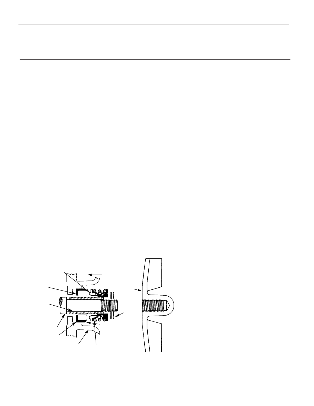
MECHANICAL SEAL REPLACEMENT
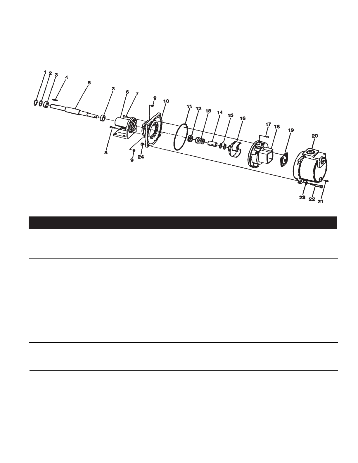
Refer to Figures 1 and 2.
IMPORTANT: Always replace seal seat
(Ref. No. 12), seal head (Ref. No. 13),
and shaft sleeve (Ref. No. 14) to insure
proper mating of mechanical seal
components!
1. Unthread cap screws (Ref. No. 22)
and remove casing (Ref. No. 20) and
o-ring (Ref. No. 11) from adapter
(Ref. No. 10).
2. Unthread round head screws (Ref.
No. 17) and remove volute (Ref.
No. 18) from adapter.
3. Unscrew impeller (Ref. No. 9) from
pump shaft (Ref. No. 5). Remove
impeller shim(s) (Ref. No. 15), shaft
sleeve, and seal head from pump
shaft.
4. Unthread hex flange screw (Ref.
Nos. 7 & 8) and remove adapter
from pedestal mounting face.
5. Push seal seat from adapter recess
with a screwdriver.
6. Clean adapter recess before
inserting a new seal seat.
7. Carefully wipe polished surface of
new seal seat with a clean cloth.
8. Wet the outside of rubber portion
of seal seat with a light coating of
soapy water.
9. Press new seal seat squarely into
cavity in adapter. Use finger pressure
only to avoid scratching seal seat.
(This is a lapped surface and must be
handled very carefully.)
10. After seal seat is in place, insure that
it is clean and has not been marred.
11. Using a clean cloth, wipe shaft and
make certain that it is perfectly
clean.
12. Secure adapter on pedestal
mounting face.
Tighten hex flange
screws EVENLY to
avoid cocking rabbet on pedestal
mounting face.
13. Apply a light coating of soapy water
to inside rubber portion of seal head
and slide onto shaft sleeve. Slip shaft
sleeve with seal head onto pump
shaft with polished face toward seal
seat.
Do not touch or
wipe face of
polished surface part of seal head.
14. Replace any impeller shim(s)
removed in disassembly.
15. Screw impeller back in place,
tightening until it is against shaft
sleeve.
16. Remount volute and position o-ring
in place.
IMPORTANT: Always inspect o-ring.
Replace when cracked or worn. Wet
o-ring with soapy water for ease of
assembly.
17. Remount casing.
Please read and save this Repair Parts Manual. Read this manual and the General Operating Instructions carefully before attempting to
assemble, install, operate or maintain the product described. Protect yourself and others by observing all safety information. The Safety
Instructions are contained in the General Operating Instructions. Failure to comply with the safety instructions accompanying this product
could result in personal injury and/or property damage! Retain instructions for future reference.
2-Inch Trash Pedestal Pumps
Refer to form 1808-635-00 for General Operating and Safety Instructions.
3931-250-00 11/2002
Specifications Information and Repair Parts Manual 3931-99
Description
This self-priming (to 20 ft. lift) centrifugal pump includes a clog resistant, open
impeller capable of handling solids as large as 1" diameter (up to 25% by volume).
A built-in check valve assists in priming and a mechanical seal prevents leakage. All
seals are Buna N. Handles liquids from 40º to 180º F (4º to 82º C). For use with
nonflammable liquids compatible with pump component materials.
Performance Chart GPM of Water at Total Head in Feet Max**
Power Req. 10' 20' 30' 40' 50' 60' 70' 80' Head
5HP @3600RPM 155 145 134 123 110 90 65 40 92 ft.
(**) Shut-off; to convert to psi, divide by 2.31.