www.amulethotkey.com FX2s FX400 CoreModule (T4 Single-Width Taco) Quick Start Guide
Health and Safety (Refer to legislaon sheet LS-AHKL-0001)
• This device complies with part 15 of the FCC Rules (Class A)
• Operang temperature range: 15° to 35° C (59° to 95° F)
• Operang humidity range: 10% to 80% (non-condensing)
For product documentaon, downloads and technical assistance, visit:
For further informaon on all our products, visit www.amulethotkey.com.
© 2020 Amulet Hotkey Ltd. All rights reserved.
Informaon in this document is subject to change. No part of this document may be reproduced through any means including (but not limited to) electronic or
mechanical, without express wrien permission from Amulet Hotkey Ltd. Amulet Hotkey Ltd may have patents, patent applicaons, trademarks or copyrights or other
intellectual property rights covering subject maer in this document. PC-over-IP, PCoIP and the PCoIP logo are registered trademarks of Teradici Corp. Amulet Hotkey
is a registered trademark of Amulet Hotkey Ltd. Other product names and company names listed within this document may be trademarks of their respecve owners.
Amulet Hotkey products are designed and built in the UK.
3 Press in the release tab on the top of the module lever.
4 Pull the module lever down prior to inserng into the expansion bay.
5 Align the connectors on the rear of the FX400 CoreModule module with the
expansion connector at the rear of the FX2 chassis. See Figure 4.
6 Push the module into the expansion bay so it is almost fully installed.
7 Push the card-puller lever up unl you hear a click. The module is installed.
Figure 4: Install the FX400 CoreModule module in a PCIe expansion slot.
A fully populated chassis looks like Figure 5.
Figure 5: A populated FX2s chassis with eight FX400 CoreModule modules
Set up the FX400 CoreModule
Cauon: !
Follow the requirements for proper thermal control of the FX400.
Sled iDRAC Minimum BIOS Minimum requirement
FC430 iDRAC8 2.10.5 2.70.70.70 rmware installed
FC630 iDRAC8 2.10.5 2.70.70.70 rmware installed
FC640 iDRAC9 2.6.3 4.00.00.00 rmware installed
FC830 iDRAC8 2.11.0 No minimum rmware requirement.
Fans must be set to medium or
higher to avoid overheang
1 Install the latest approved iDRAC on all compute sleds in the FX2s chassis.
See our support website and the Tech Note for the latest approved versions.
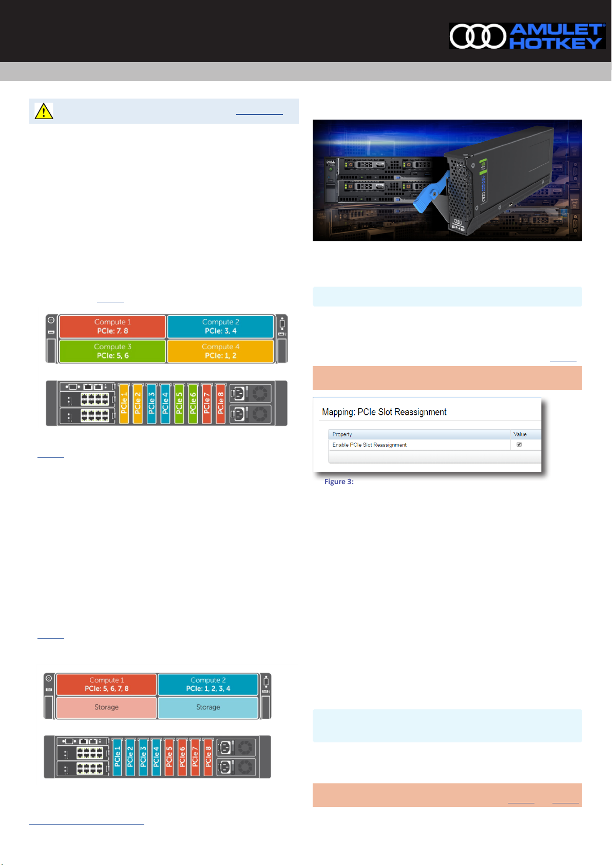
2 To select the conguraon in Figure 1, make sure the checkbox for Enable
PCIe Slot Reassignment is deselected.
3 To select the conguraon in Figure 2, make sure the checkbox for Enable
PCIe Slot Reassignment is selected.
4 Power on the blades in the FX2s chassis.
5 Set the BIOS seng SR-IOV Global Enable to ENABLED.
6 To set up expansion modules for VDI conguraon, and for more detail on
PowerEdge sled mappings, see KBA 113 - Set up VDI for the T4, DXG-M6,
DXG-P6 and DXF-G cards for essenal informaon.
To remove the FX400 CoreModule
Cauon: !
Always use an-stac handling procedures such as wearing a
wrist-strap before handling the FX400 CoreModule module.
1 Shut down or migrate all VMs hosted by the blades.
2 In the VMware vSphere client, locate the ESXi server in the Inventory and
put it in to Maintenance Mode.
3 Power down the blades that map to the FX400 CoreModule module.
4 Press in the release tab on the top of the module lever.
5 Pull the lever down. This ejects the module from the connectors on the
backplane of the chassis.
6 Carefully draw out the FX400 CoreModule module and t the connector
protector that came with the unit. See Figure 6.
7 Put in a suitable an-stac bag.
Figure 6: Remove the FX400 CoreModule module from the FX2s chassis
To set the fan speed (necessary only on FC830)
Either (From the CLI):
1 Use an ssh client (port22) to login as root (default password ‘calvin’).
2 Enter $ racadm fanoset -s medium
Or (From the GUI):
1 Log in via a browser to the CMC IP address. Select fans from the side menu.
2 Select the Setup tab and select medium from the drop down menu.